This document proposes new concepts for geometry nodes that solve many of the existing usability problems and add a lot of new flexibility.
Fields
Definition
We have different socket type for different primitive data types. For example, there is a float, a vector and a boolean socket type. What these types have in common is that they always just carry a single value of their data type. This is what this proposal wants to change. Instead of always carrying a single value, now these sockets carry a “field” (the naming is of course open to debate, but I’ll stick to that for now). Everything else about the sockets stays the same. Nodes using these sockets also don’t really change. The math node shown in the image below looks exactly the same with and without this proposal.

So what is a field? A field is a function that outputs a single value of the corresponding data type. A float field computes a float and a boolean field computes a boolean. While the field can only have a single output, it is allowed to have an arbitrary number of inputs/dependencies. These inputs are provided by the node evaluating the field. A field that has no inputs always outputs the same value. Therefore, it is a constant and works exactly the same as the sockets we have today.
Every dependency of a field should also have a default value. This way it can be evaluated even when not all dependencies are available.
Note, this definition of a field is different from definitions in mathematics and physics. While the term is inspired by the fields used in physics, they can depend on more than just space and time in this proposal.
Usage
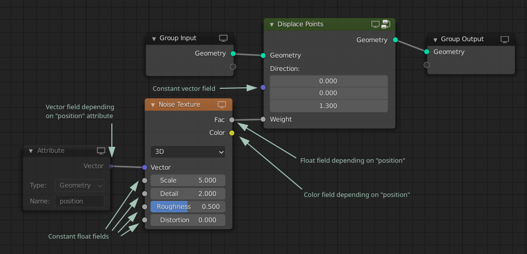
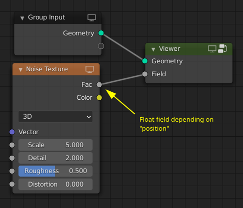
One of the simplest demonstrations of where this can be used is in a node that displaces all points in some direction. In the image below the Attribute node is optional, because if the vector input to the noise node is not connected, it implicitly depends on the position attribute (this is the same behavior as in shader nodes). Note how it would be possible to use the same texture node group in shader and geometry nodes in this setup.
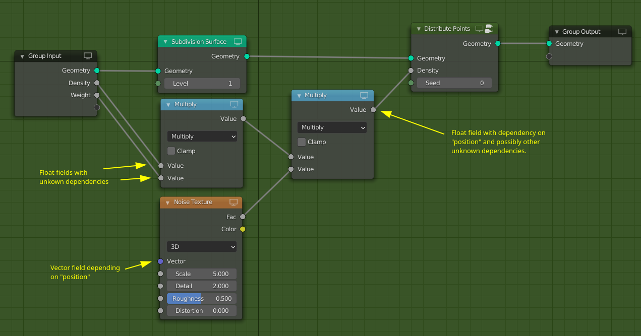
In the next example, I want to build a node group that first subdivides the incoming geometry and then distributes points on the new geometry. Furthermore, it modifies the incoming density weights a bit. Note how it is possible to edit the geometry without making the fields incompatible in most cases.
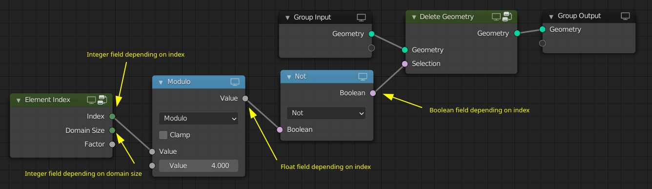
So far we only depended on attributes that exist on the geometry. However, it is also possible to depend on other things like the index. Note that in the example below, the Delete Geometry node would need a domain dropdown, which seems reasonable.
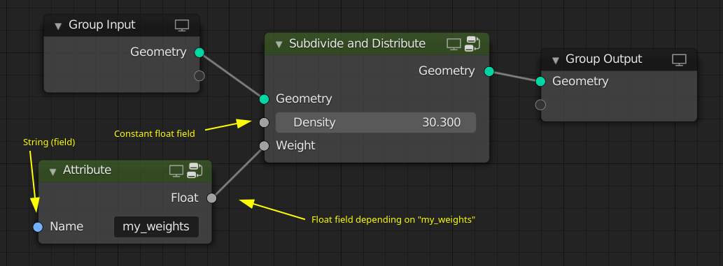
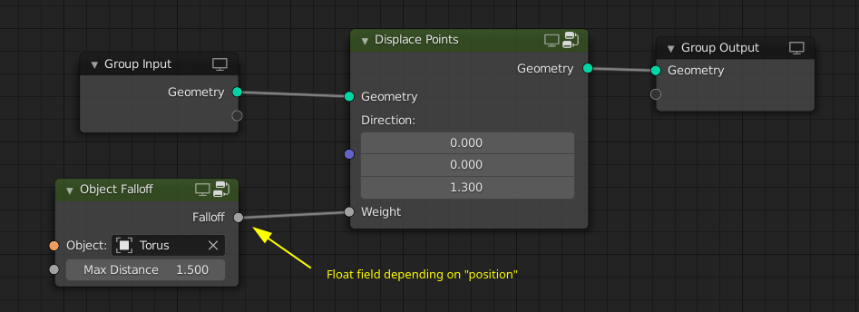
With fields one can build node groups that compose well and encapsulate high level concepts for the user. For example, one can build “object falloffs”, i.e. float fields that are one very close to an object and are closer to zero the further you are away.
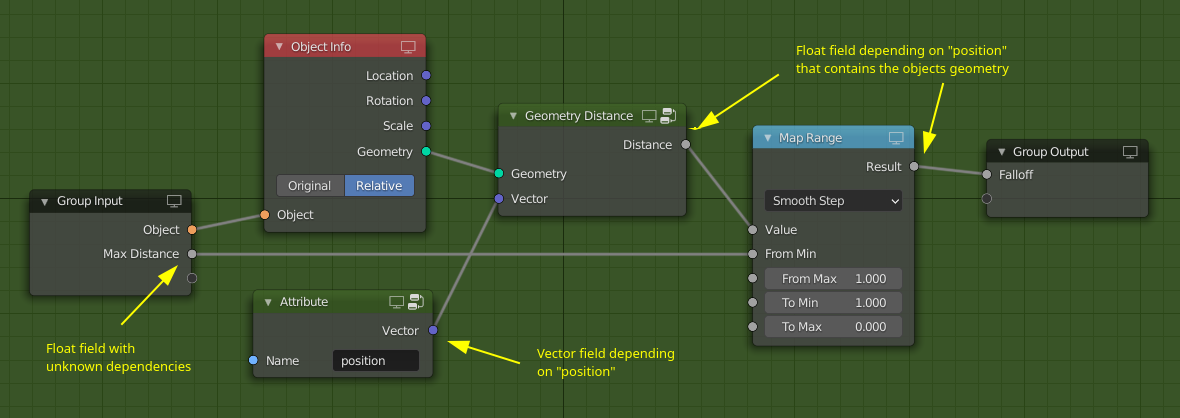
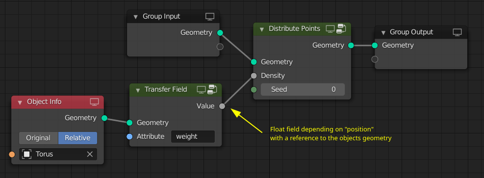
In the above example, the falloff float field contains a reference to the object’s geometry. Otherwise it would not be able to compute the distance to it. This solution opens up even more possibilities with respect to attribute transfer between geometries. In this example, the weight attribute from a different geometry is used to distribute points. The “transfer field” will find the closest point on the surface of the geometry and output the attribute value on that point. The same approach can work for volume grids as well.
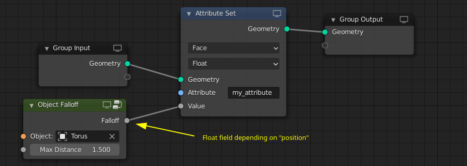
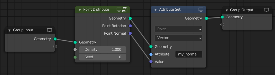
To store a field as an attribute on a geometry, the Attribute Set node can be used. This way it can be passed e.g. to the renderer.
Anonymous Attributes
Definition
An anonymous attribute is like normal attributes with a few key differences:
- It does not have a user provided name. Instead it has some randomly generated name that the user should never see. It might also have a “debug name” that helps understand where the attribute comes from, but this name cannot be used as identifier.
- Its generated name is reference counted.
- Once no one has a reference to the name anymore, the attribute can be freed automatically.
Usage
As a first example, let’s have a look at the Point Distribute node. Instead of generating attributes with hardcoded names, it generates anonymous attributes for rotation and normal. Furthermore, it outputs two vector fields which depend on the anonymous attributes.

Note, the Point Distribute node can see that the normal output is not used, so it does not have to be generated. Also, once the Point Instance node has evaluated the rotation input, this vector field is freed. This results in the reference count of the anonymous attribute to go to zero. Therefore the anonymous rotation attribute is not transferred to the new points (if we would support that).
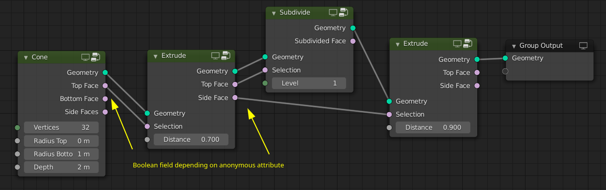
The next example shows how anonymous attributes and fields can be used for procedural mesh modelling. Note how it is possible to subdivide some faces without making the other selections incompatible. Another nice aspect is that nodes only generate the selections that are needed and they will be freed automatically once they are not needed anymore.
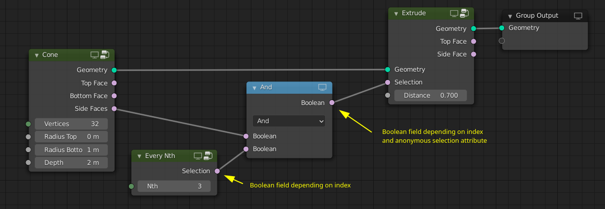
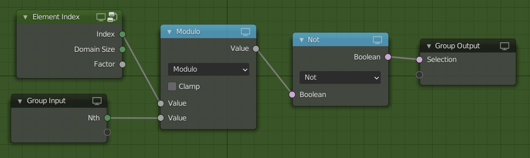
It’s possible to combine selections as well. E.g. in this example every third side face of the cone is extruded.
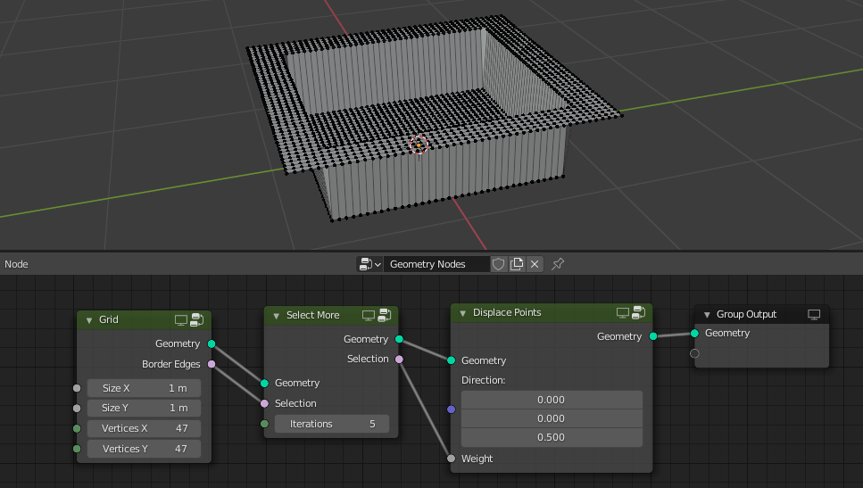
Expanding an existing selection can look as shown below. Note that in order to work well this node needs the geometry.
If the user wants to give an output attribute a name explicitly, an Attribute Set node can be used.
Debugging
Fields with dependencies are harder to debug than attributes that are stored on a geometry. That is because such fields need more context (usually a geometry) to be evaluated to actual values.
Node Warnings
The first level of defense against wrong use of fields are warnings on nodes. Whenever the user passes a field to a node that cannot provide all inputs to the field a warning should be shown. This typically happens when the field depends on an attribute that does not exist on the geometry or when the node only allows a constant value for an input.
Socket Inspection
When hovering over a socket we can show the last evaluated data that passed through the socket. This is planned for some time already and still has to be implemented. For fields socket inspection should show the fields dependencies. In some cases it could also show the entire field as an expression. For anonymous attributes the debug name is shown.
Spreadsheet
Showing fields in the spreadsheet next to other geometry data can be very useful. Unfortunately, it is a bit more difficult, because a field is not just a list of values. Unless the field is a constant or only depends on the index, it is necessary to provide context for the field evaluation. This context is typically given in the form of a geometry that the field is evaluated on.
One solution that I currently like is to extend the concept of the viewer node. Instead of just accepting a geometry, the viewer could also have a field as input. In this case the first column of the spreadsheet can become the evaluated field.
Different shortcuts can be assigned to connecting a geometry or field to the viewer node. This way one can set one geometry as context and then quickly select different fields to show in the spreadsheet. Anonymous attributes can be shown in the spreadsheet like any other field.
Viewport
Once the viewer node can display geometry in the viewport, we can also show the field that is connected to the viewer in the viewport.
Evaluation
The fields and anonymous attribute concepts do make the socket value and attribute concepts more complex. For me, these complications are well worth it given the problems that they solve and the additional flexibility they provide. With the mentioned debugging solutions, exploring what fields are should become much simpler.
Here are some benefits of this proposal:
- Attribute processing is not linear anymore.
- Temporary attributes are not needed anymore.
- Compared to lists, fields don’t become incompatible when geometry changes in most cases.
- Temporary data that has to be stored on the geometry (e.g. selections) does not need to be named explicitly and is freed automatically.
- Node groups can be shared between geometry and shading nodes.
- Texturing concepts from shading nodes map directly to geometry nodes, so less relearning is required.
- Instead of having options in nodes to determine which output attributes should be generated, this is entirely determined by what output sockets are used.
Related discussion points
This proposal also benefits from more development regarding compact nodes, socket type inferencing (automatically changing socket types depending on what is selected) and list sockets. However, those topics are orthogonal to what is presented here.
Constant Sockets UI
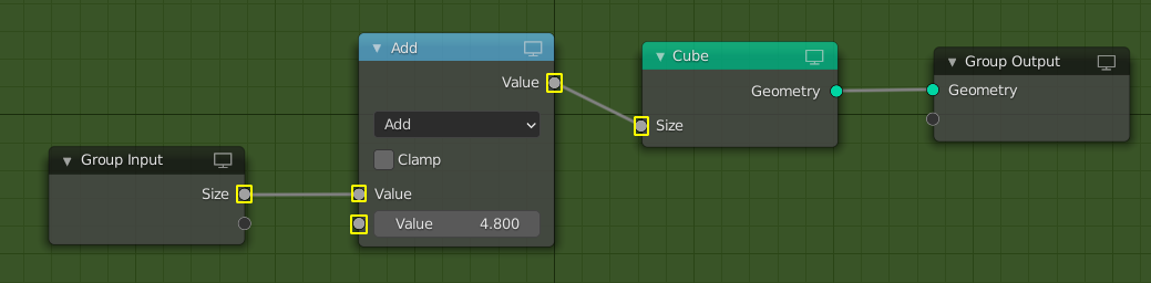
It might be useful to be able to show e.g. integer sockets differently if they do not allow a field with dependencies. Typical cases for such inputs are seed sockets and inputs to mesh primitive nodes. Generally, it should be obvious from the context when a socket does not support a field, but maybe not always.
One proposal in T74967 was to show these inputs as rectangles instead of circles. Getting this to work on built-in nodes is fairly straight forward, but making it work in more general becomes significantly harder because it requires something like type inferencing that we don’t have yet. In the image below, all the highlighted sockets should be drawn differently because they only allow constant values.
Given the complexity of a good implementation and the fact that in most cases this should be clear from context, I don’t consider this to be a blocking issue for this proposal.
Immediate Attributes and Expressions
Currently, it is possible to write an attribute name directly into the node that is using the attribute. In the current state of the proposal that is not really possible, because the enum to switch between value and attribute is not necessary anymore (both can be passed into the float socket). It can still be very convenient and less verbose to type the name directly into the node though. Extending the concept further, it makes sense to not only be able to type attribute names but entire expressions into the socket.
My currently preferred solution is that one can just click on the float socket and start typing an expression. Not exactly sure how that would work with boolean sockets yet though. This is part of the compact nodes discussion.


