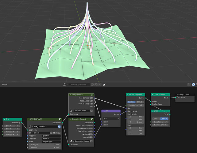
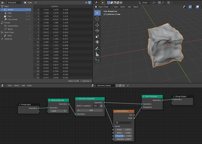
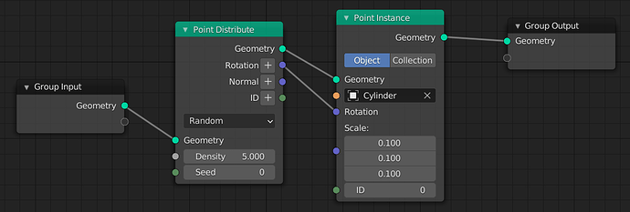
This is a refined proposal on how to handle attributes sockets. It is a streamlined version of the Attributes Sockets proposal with the following differences:
- No hard-coded names are expected/required, not even for local attributes.
- Nodes that output a geometry and new attributes can have its attributes accessed directly as lists, and/or appended to the outputted geometry.
- The geometry socket can be expanded to get or pop its individual attributes.
The first two parts (“Attributes and Attributes Sockets” and “Geometry Nodes Modifier”) are copied from the original proposal.
Attributes and Attribute Sockets
Attributes are commonly referred to as columns. This is a reference to how they are visualized in the spreadsheet. Attribute sockets are sockets that pass an entire column from the spreadsheet containing:
- List (array) of elements.
- Datatype (float, integer, boolean).
- Domain (vertex, face, …).
So far every node were allowed to read and write any attribute to the geometry, and the result was incorporated as part of the outputted geometry. This leads to an extremely linear nodetree that makes it hard to read.
Instead, it will be interesting to pass the attributes around directly, so the operations can happen independently of the original geometry.
This was avoided in the original design because users can easily shoot themselves in the foot by connecting attributes from geometries with different index orders or length leading to unpredictable results. At the moment though, its benefits outweigh those issues.
Selections are just a an attribute socket with a list of booleans.
Geometry Nodes Modifier
Let’s start by looking at a simple geometry node modifier. The first new thing you can see is that all the
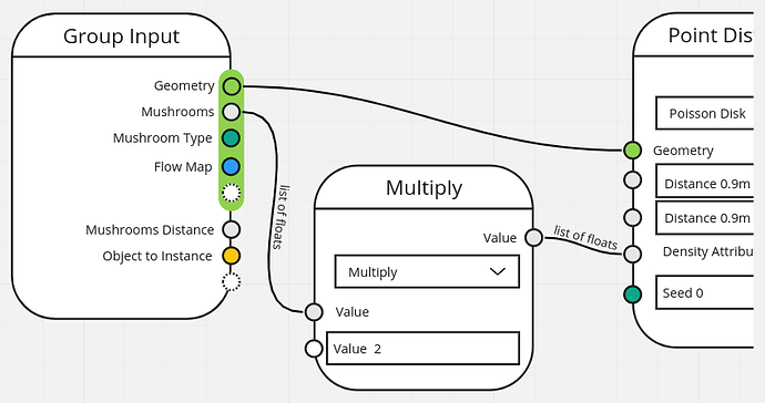
attributes expected from this mesh and generated from the node tree are explicitly visible in the modifier.
Note also that those attribute fields (mushroom, scale, rusty_weight, mushroom_uv) are not simply strings. They are attributes that are expected to exist in the mesh. While they are referred to as strings, inside the nodetree they are passed around as attributes (i.e., list of values).
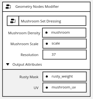
Geometry and Attribute Inputs
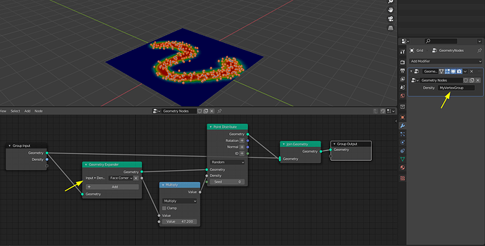
Geometry Socket can have multiple Attributes sockets accessed from it. Those are the attributes exposed outside the modifier and mapped to UV maps, vertex groups, … The non-exposed attributes (e.g., other UV maps) are still preserved with the geometry and interpolated during topology changes.
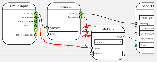
Those exposed attributes are part of the geometry socket and passed along with it. However they can also be accessed directly. In this example the Mushrooms attribute is a vertex group mask defined in the modifier that is multiplied by two. It is then passed to the Point distribute node.
When the nodegroup is used inside another nodetree attributes can also be passed individually as a list, detached from any geometry socket.
Expanded Geometry Socket
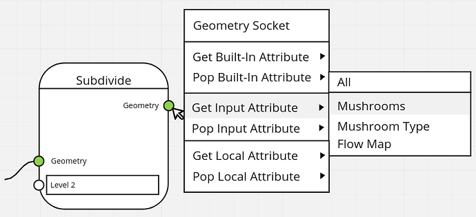
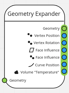
At any point a geometry socket can be expanded to explicitly expose one of its accessible attributes:
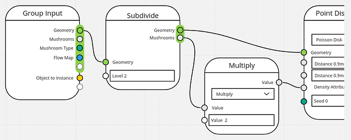
This allows those attributes to be passed around as a list directly from its current values (not the ones from the Group Input). This is particularly useful when the geometry went through topology changes.
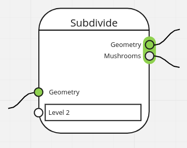
The Mushrooms list accessed after the Subdivide node has more elements than the one obtained directly from the Group Input. It can be used with the Point Distribute node for the subdivided geometry.
Geometry Expand Node
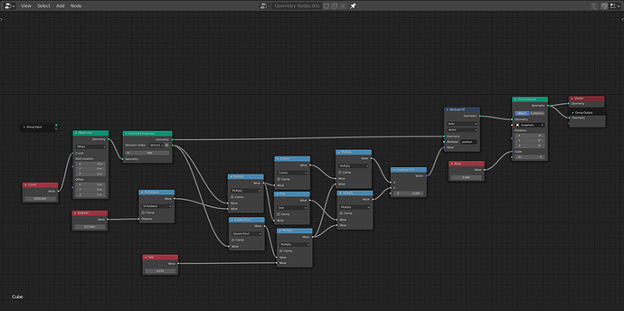
A “Geometry Expand” node should support the same socket expand operations. Similarly, a “Geometry Compose” node should allow the existing attributes to be replaced by different lists, besides adding new attributes to a geometry.
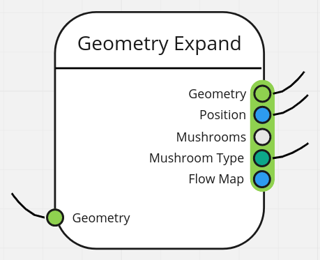
Attributes Outputs
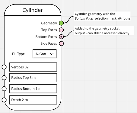
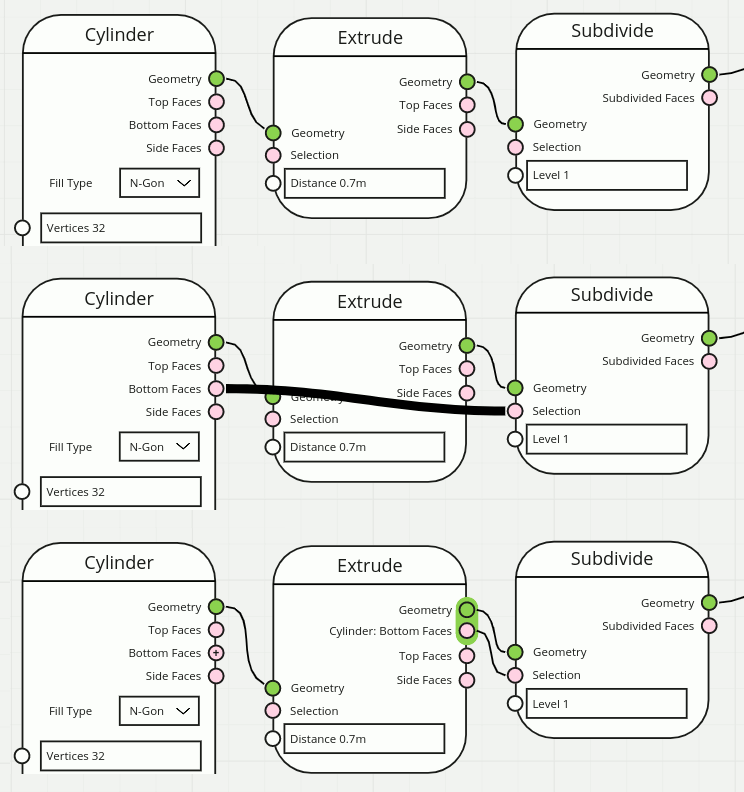
New outputs created in a node are explicitly exposed as list outputs in the node. By default they are not passed with the geometry.
However, if an attribute needs to be accessed later, after the topology of the geometry changed, its sockets can be added to the geometry.
To simplify adding attributes to the geometry and access them, this can be automated when dragging using an extra keyboard modifier (ctrl / alt / shift):
Attribute Domains
When converting from an attribute to a list it is important to indicate which domain this is intended to be used with. The value can then be interpolated from its original domain if needed.
This applies for both input and output attribute sockets. They were omitted in the other images in this proposal to keep things simple. But every attribute socket needs to have its domain identified.
Attribute Outputs and Local Attributes
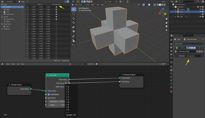
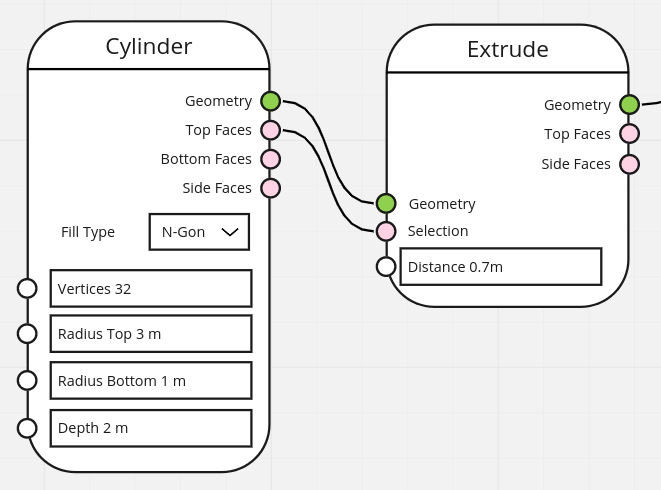
Local attributes are attributes that were not in the original input geometry. They are accessible inside the entire node tree. However they are not automatically outputted with the geometry outside the node tree.
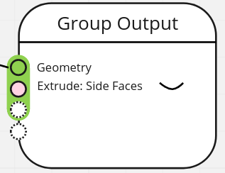
They need to be explicitly picked to export — in this following example Extrude: Side Faces is not outputted with the geometry (see the hidden icon). The outputted attributes need to be mapped in the modifier to an existent or new attribute.
UI/UX Design Challenges
- What does an expanded socket look like?
- How to expand a geometry socket to get or pop an attribute?
- Different types of attributes should be visible differently in the spreadsheet and in the node tree.
- Attributes sockets have an explicit domain for input and output that needs to be visible.
- Lists sockets (e.g., attribute sockets) should be different than their regular counterparts of the same data type (float, integer, …).
- Attributes outputted from nodes can be “added” to the geometry, need a visual language for this.
- Attributes expanded from a geometry socket can be popped or stay in the socket, need a visual language for this.
- The modifier and node user interfaces will need a new way to organize its buttons to allow for geometry attributes to be intercalated with other inputs.
- Object info will need to change to be treated as an Input too, so users can map the Object as well as the expected attributes to operate on (at least when the object is defined in the modifier, not inside the nodetree).
Related posts:
