Geometry nodes supports volumes for some time already with Volume to Mesh, Mesh to Volume and Volume Cube nodes. However, many basic features as simple as modifying volumes are not supported yet. This document proposes a new way to integrate volumes into geometry nodes that removes many existing limitations.
Grid Socket
At the core of this proposal is a new kind of socket for grids. It has a new socket shape and exists in multiple variants for the different base types.
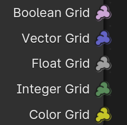
The data in a grid socket corresponds to an unnamed OpenVDB grid. That means it contains:
- The full topology information (active and inactive voxels and tiles).
- A transformation (also determines voxel size).
- The data that is stored in each active voxel and tile.
- A background value that used used wherever the grid is not active.
Tiles are storing grids that have the same value in many neighboring voxels more efficiently. The concept of tiles is exposed to the user, because it’s important to be aware of them to be able to optimize node setups in some cases.
Volumes in Geometry Sockets
The Volume component in geometry can contain multiple grids. Each grid either has an explicit name or is anonymous. Grids are similar to attributes in many ways, but working with them is a bit different than with other attributes. Grids within the same volume do not have to be aligned. It’s often recommended that they are though because that can lead to better performance because less resampling is required.
An important difference between grids and e.g. mesh attributes is that grids can exist on their own, because each grid contains its own spacial information. Mesh attributes are always attached to some mesh.
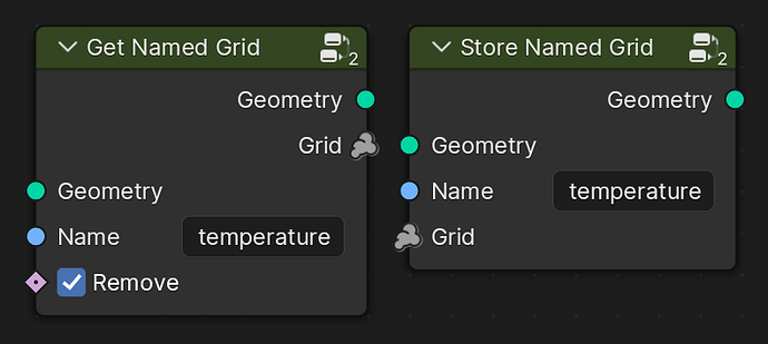
Grids can be extracted and inserted into a geometry with specialized nodes. The Store Named Grid adds a new grid, potentially replacing an existing grid with the same name. The Get Named Grid node gives access to a named grid in a volume. The Remove input mainly exists to allow for better performance by avoiding accidentally having the same grid twice in memory.
For common cases, we can optionally add special nodes (or node groups) to make it easier to work with certain naming conventions.
Anonymous Grids
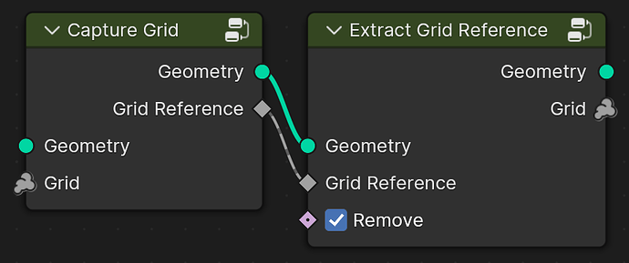
Supporting anonymous grids in a volume is a little less straight forward and requires a solution to the problem of referencing anonymous attributes. Note, that the Grid Reference input requires a field that is an grid reference, it can not be an arbitrary field. Because grids are usually processed separately from geometry and also more expensive, anonymous grids are likely less common than anonymous attributes.
Converting between Grids and other Geometry Types
We already have some nodes to do this, but they’ll change with this proposal. Instead of working on a geometry directly, they work with grids instead. The nodes only have a “Voxel Size” input to make using the same transform simpler and to avoid using arbitrary heuristics within each node. A Bounds to Voxel Size node group replaces the old “Resolution” behavior from existing volume nodes.

Fog Volumes and SDFs
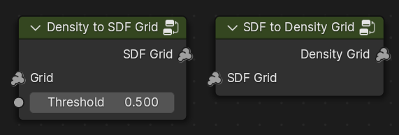
Both, fog volumes and SDFs (signed distance fields) are represented as grids. Special nodes can be used to convert between them.
Building Grids from Scratch
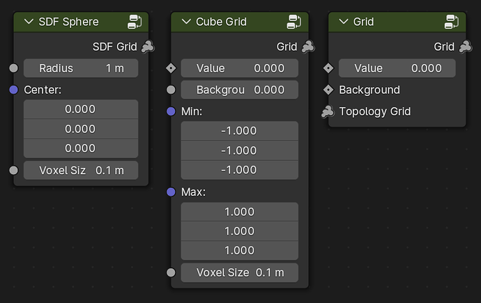
Multiple different nodes can be used to build grids from scratch:
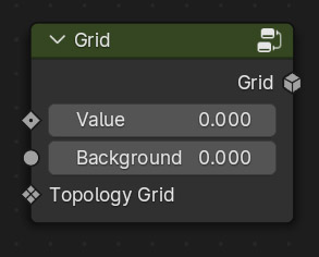
SDF Sphere: Creates a new SDF grid for a sphere with the given size and center.Cube Grid: Similar to the existingVolume Cubenode, but a bit more general since it can create grids of arbitrary types.Grid: Initializes a new grid based on the topology of an existing grid. Each value is initialized with a field. Note that the data type of the topology grid does not matter since only its topology is used.
Changing Topology without Changing Values
These nodes change which voxels and tiles are used while representing approximately the same data. They can be used to prepare grids for later operations.
Value Processing
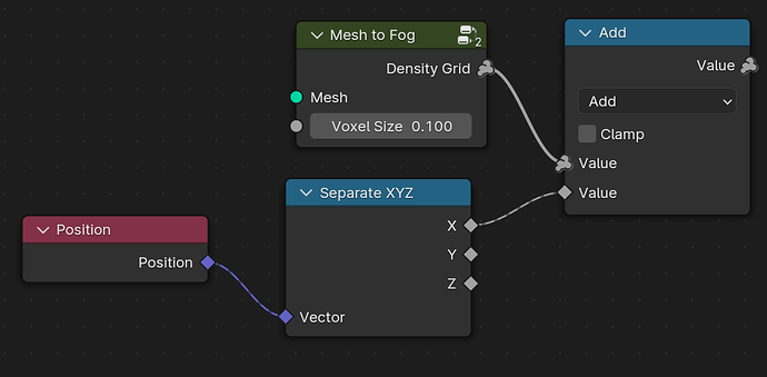
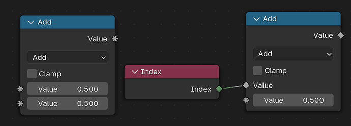
Function nodes like the math node allow the inputs to be grids. If at least one input is a grid, the output is a grid as well. Non-grid inputs can be single values or fields. All grid inputs have to be aligned, i.e. have the same transform. The output grid will have the same transform as well. The active voxels and tiles in the output will generally be the union of the input grids.
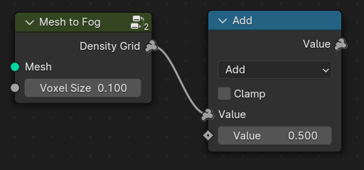
If an input is a field, it is evaluated in the context of each active voxel and tile in the output grid.
This will probably require a new socket shape to tell the user which inputs allow single values, fields and grids. This patch proposes a new asterisk shape for that purpose.
Note, while every math node creates a new grid on the user-level, internally it probably a good idea to group a bunch of math nodes together and avoid intermediate grids as long as the final result is not affected.
Voxel Field Inputs
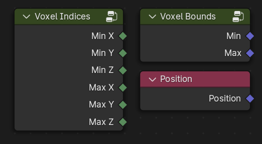
A new kind of field context for voxels is added. It supports new field inputs. Those field inputs just output default values when they are used in non-voxel contexts. The Position input gives the voxel center. Using the same node makes node groups more reusable. The Voxel Indices node gives the position of the voxel in the index space of the grid. It has to give the min and max because tiles can span multiple voxels.
Accessing Grid Values
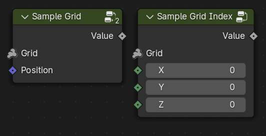
Individual values in a grid can either be accessed based on their position in object space using the Sample Grid node, or with index values in grid index space using the Sample Grid Index node. The former may also interpolate between different voxel values. Its position input defaults to the Position node.
Aligning Grids
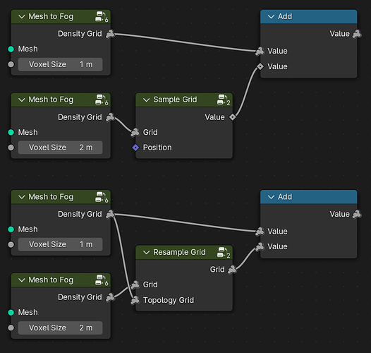
All grids passed into a a function node have to have the same transform. If they don’t, there is an error and the user has to make sure that they align. This is important because there are different ways to align grids and which one is used can have a big impact on performance and final result.
There are two main ways to align grids: with the Sample Grid or with the Resample Grid node. The main difference is that when the Sample Grid node is used, the result it a field, so the topology does not affect the topology of the output of the function node.
Debugging
Grids contain all information necesssary to display them, so they can just be connected to a viewer (which has to be changed to support grids) without the need for a geometry socket.
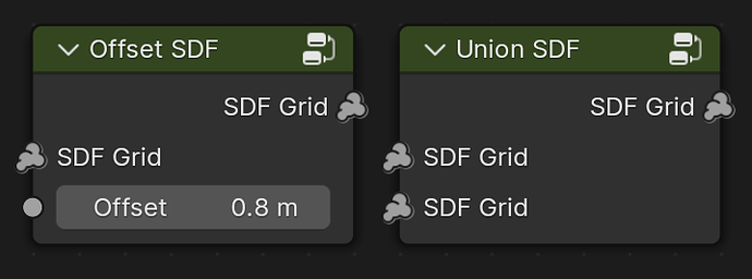
Modifying SDFs
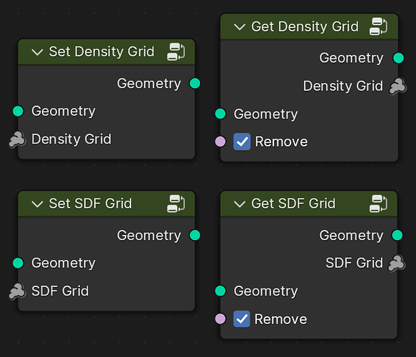
The image below shows two nodes that can be used to work with SDFs. Many more nodes are possible of course.
Advection
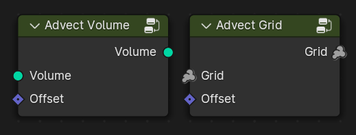
This section serves as an example for how to differentiate nodes that deal with individual grids and those that work on all grids in a volume.
FAQ
- Why a new socket type? A separate socket type maps more naturally to how people use grids. The definition of fields would have to be extended to contain data from the context like the active voxels. Then the field itself would affect the context it’s evaluated in. Also, because grids can be standalone data, the design constraints are different than for processing attributes on other geometry types.
- Is there other data that would be processed similarly? Yes. Lists could be processed separately from geometry in a similar way, at the cost of more manual domain handling. Making geometry data flow more explicit would often be helpful too. It’s also possible to imagine sockets for acceleration structures like 2D grids or KD-Trees in the future.
Revision History
- Renamed
SDFsockets toSDF Grid - Added
Voxel Coordinatenode - Changed
Voxel Centernode toPosition - Changed advect velocity inputs to fields
- Added units to some inputs
Mesh to Density Grid,Density Grid to Mesh- Partially filled boundary voxels mostly only make sense for density and not so much for e.g. temperature.
Mesh to SDF Grid- “SDF” is just a math function, while a grid is a rasterized function.
- Also applies to
Offset SDFandUnion SDF.
- Also applies to
- Exposing the boundary thickness (“bandwidth”) might be a good teaching moment.
- “SDF” is just a math function, while a grid is a rasterized function.
Density to SDF Grid,SDF to Density Grid- Whatever grid is passed into the former node is interpreted as density (0 is “empty”).
- Needs a threshold input.
- “Voxel Size” input requires logarithmic input slider to avoid crashing things too easily.
- This way we don’t really need the resolution input anymore which mainly exists to solve that problem.
- Could provide a node group that computes a “good” voxel size from a geometry (bounding box) and a resolution.
- Makes it easier to not have to implement the resolution behavior in all volume nodes.
- Even if we replace the “Voxel Size” input with a transform matrix later, it would still be good to have a slider to control the size in the node.
- On the other hand, not having a slider would make it more obvious that the same transform should be used in all volume nodes.
Resample Gridonly takes the transform of the reference grid into account.- The reference grid should not be called
Topology Gridthen.
- The reference grid should not be called
Simplify Grid,thresholdvs.epsilon- it’s a delta for comparisons
- Check what name openvdb uses, same for
Densify
- Might need a special resampling node for SDFs.
- It has to make sure that the bandwidth is a few voxels large.
- A possible alternative to supporting grids in every function node could be to always use a
Gridnode when creating a new field.- Keeps the behavior of the function nodes simpler.
- Has the benefit that the user can know for sure that there are no intermediate grids (which can use a lot of memory).
- The downside is that it makes simple math operations harder on grids because one always needs the extra
GridandSample Gridnode. - We want function nodes to work similarly on grids and lists in the future, and for lists it seems more obvious that function nodes should be able to modify them directly.
Voxel Coordinatesshould be calledVoxel Indicesbecause coordinates tends to imply “positions”.Sample Grid+Sample Grid IndexAdvect Grid/Volumenode input should beOffsetinstead ofVelocity.- “Velocity” indicates something with time.
