As the backwards bidirectional gizmo socket is so weird maybe attach the gizmo to the top or bottom of the value node it influences to show it’s a very different sort of link?
I think the (psychological) weirdness is caused by that the value node and the gizmo controlling it are intricately bidirectionally linked which doesn’t really fit the normal nodetree pradigm.
I think this is nice, but the value should flow into the node and the node effects it and puts it out,
it makes it more intuitive to understand the evaluation order.
perhaps a ‘create gizmo’ node and then it has loc / rot / scale
and the end user can pick the values it outputs (even all of them!)
I don’t really think splitting it into a ‘display’ and ‘value’ part helps much. I also don’t see where you put in the actual value for y in your mockup. But maybe I don’t really understand it.
Ideally a gizmo (imho) should behave as if you just dragged on the value of a value node, but in the viewport.
Like Brecht says above:
The problem with this is that the gizmos should be able to directly influence the settings in the modifier panel (so the values in the group input node) , so the value of the gizmo needs to flow ‘back’ somehow.
Thinking about this some more this also means my top/bottom connection idea doesn’t work, because the group input node has many connections.
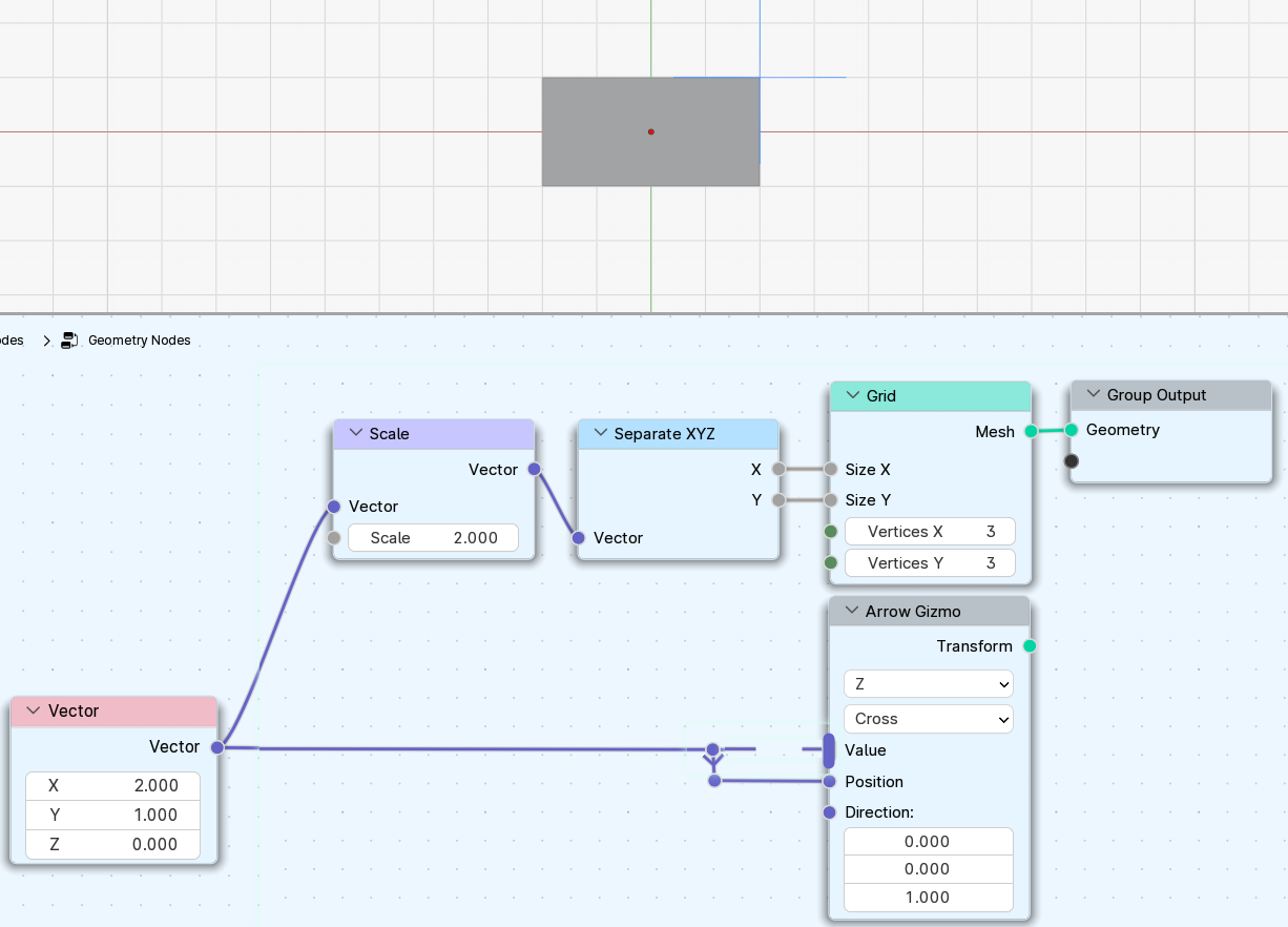
Since the group input “X” is set to use the gizmo Index “1”, and the “Gizmo value” node, which is connected to “Y”, is set to use the same gizmo of index “1”, they both use the exact same gizmo and have the exact same value. So, if you either move the gizmo in the 3D view, or change the “X” value on the modifier, the “Y” changes to the same value as well.
Perhaps “Index” should be renamed to “ID”. Probably makes more sense. It identifies which gizmo the “Gizmo value”, “Gizmo display” or a nodegroup input are referring to.
I thought about it some more. What wouldn’t work if the value was implicit and hidden from the node network?
What I mean is that the gizmo value would be on the output side, not input side, and each gizmo would have a simple toggle whether you want to show its value on the input. If enabled on the top level node network, the gizmo value would show as a setting on the modifier panel, and if enabled on a gizmo node inside node group, the value would show as a node group input.
So gizmos would be something similar to a single-input Group Input node. This would mean we still don’t need the reverse direction flow concept and we don’t need a dummy value/constant node for gizmos to work properly.
Excited to see gizmos coming to geometry nodes! Thanks!
Many things have already been said in this thread, so just small suggestions.
The plane draw type on the Arrow Gizmo node doesn’t make much sense when it can only output a single number. That’s probably something considered already, but in case it isn’t: It is generally used to drive two axes at once. Also, the circle gizmo can either be used for rotation or for just moving things around. So maybe these could become a third gizmo node with a vector output?
Other gizmo ideas would be:
a toggle for boolean parameters
could be used for visibility of things
increment/decrement gizmos (circle with a plus/minus in the center)
Could be used to change iterations of a repeat zone. One example would be a rollercoaster where you can click on a plus gizmo at the end and a new rail segment appears that can be moved by other gizmos
The other mentioned proposals generally solve part of the problem but fail to solve all of them, at least not without adding additional complexity. Common issues are:
Values controlled by a gizmo is somehow special and can not be driven by either means, especially procedurally, with keyframes or with drivers.
A principle we generally try to follow is that when grouping a single node, this group should have the same behavior as the original node (doesn’t work with e.g. enums yet, but we are working towards it).
It introduces a new kind of “backlink” using IDs that is semantically the same as having some link in the node tree but is more hidden.
It assumes that the mapping of gizmo-changes to value-changes is a constant factor that can be input manually and is not affected by other values in the node tree.
It does not work with the use case where we want to add a gizmo for e.g. each point to drive attribute values.
It’s up to the user to decide what the gizmo controls. It is already possible to make it affect two axes.
Note that a gizmo node does not output the values. Instead, it attaches a gizmo to a value stored elsewhere.
It’s quite possible that we’ll add built-in gizmo nodes that can affect e.g. an entire vector or rotation. Just maybe not initially.
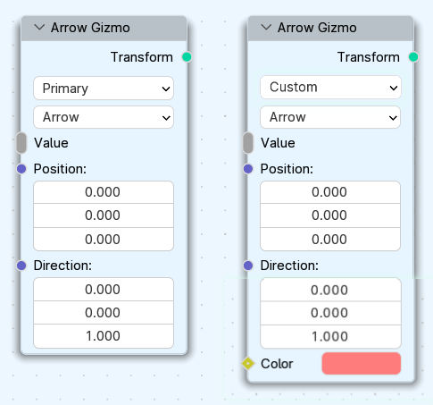
How about adding a custom option to the color? Keep the theme color while also having custom options.
2.How about supporting vector value? The direction only controls the direction of the gizmo, and the gizmo can be freely moved in the view without being limited by the direction.(I just noticed that it has already been discussed above.)
One thing I’ve been thinking about is gizmo that follows the curve when you drag it, instead of moving in straight line
Lets say I have vehicle and Im moving it with path curve. Will it be possible to have arrow gizmo in front of a vehicle that I can drag and arrow will also follow curve? Either with current implementation or in future?
Aware that this design idea opposes (literally) all the limitations mentioned, think of it more as a cool brochure, tucked away on the shelf of a serious conversation.
The idea is to create a Node Graph dedicated to Gizmo, based on the Geometry Node. The Gizmo is no longer a Blender gadget, but a new type of asset. So “Blender” develop the methods for using the Gizmo (see link) and the community will do the rest.
However, Blender froze several times during my gizmo experiments. I had to shut it down, start again, and continue from saved .blend file.
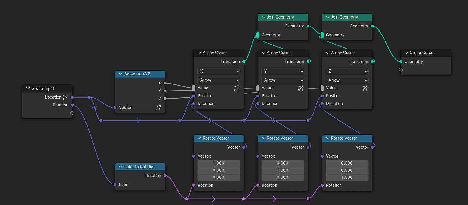
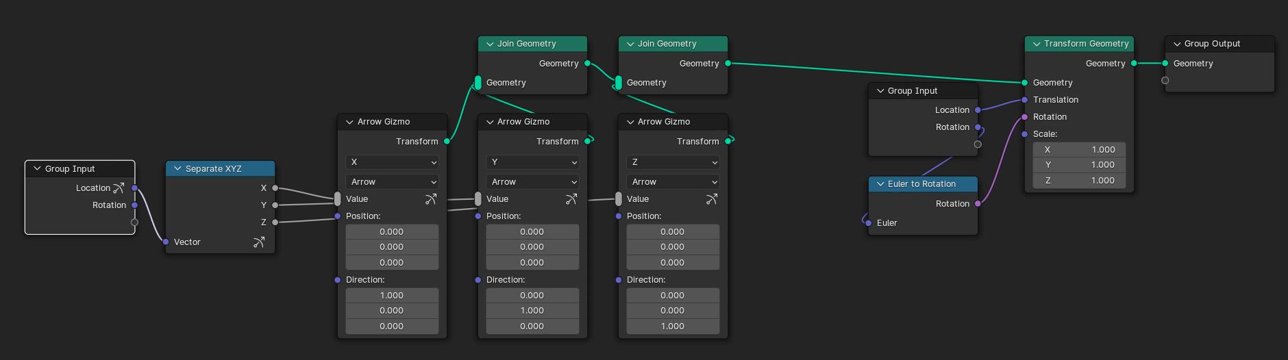
Atm, it won’t work to apply a rotation to a gizmo input. Not sure how to map values gizmo’s to control actual location coordinates in a way which respects the gizmo’s rotation.
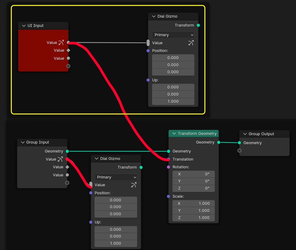
For me, it helped to plug the gizmo directly to the modifier’s group output. ( The viewer node does not work atm. )
I agree it would be great to have text “gizmo” as a overlay to display values, like if you draw text with python. To get to modifier attributes via API is cumbersome and slow.
I think there are 2 fundamental design errors: the first is the transformation, which is very useful, but at no time should the gizmo interfere with the geometry!
A solution: Why not add an “Is local” boolean input? I haven’t explored the situations where automatic recovery of transforms along the chain is a problem.
Edit :The best replacement solution I’ve found is to add a “Local Space” option that retrieves transforms from the main branch (the last branch of the geometry node), The “grid with gizmo” example would work in the same way, but there would be no need to connect the geometry.
But I must admit that my solution seems questionable…
2 : It’s the same for Value inputs: it seems to me that when you add a Value Input instead of an Input Parameter, you don’t need to control it from the outside.
So why should we be able to do it here?
It seems clear to me that any design that aims to link gizmo directly to geometry is a mistake.
I think geometry nodes are messy enough already!
It appears odd at first, but I do not think this is a mistake.
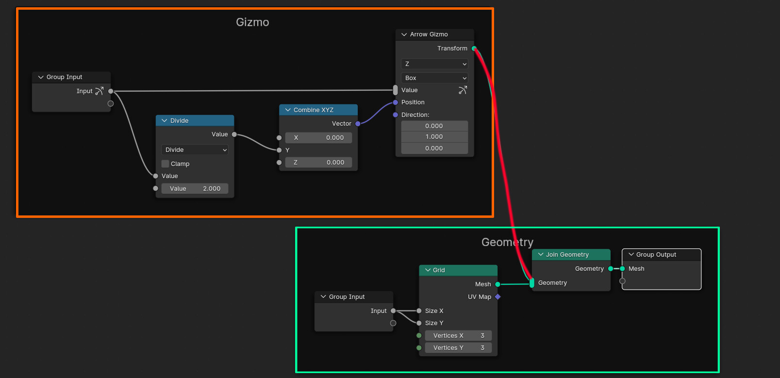
When you plug the gizmo’s transform output into a geometry-join node, it’s transformations will propagate with the geometry flow. If you transform the geometry later, the gizmo will be transformed too.
It is actually useful. There is no need for us to re-align our gizmo each time we change our geometry flow transformation.
Perhaps one way to differentiate between normal and non-normal links is simply to never mix them.
The idea is to create an Input Group specifically for Gizmos
It would be impossible to link gizmos with the classic group input.
We could also imagine a frame for the “gizmo zone”.
I was thinking of using the classic group input, but it seemed more complicated.
What about Input Value?
I don’t understand why it should be possible to control a value with a gizmo. If you want to edit your value from the outside, use an Input parameter?
The advantage of this method is that it’s much easier to read, but the setup of gizmos is more complicated.
I think that, by nature, gizmos should work in parallel and not be linked to geometry.