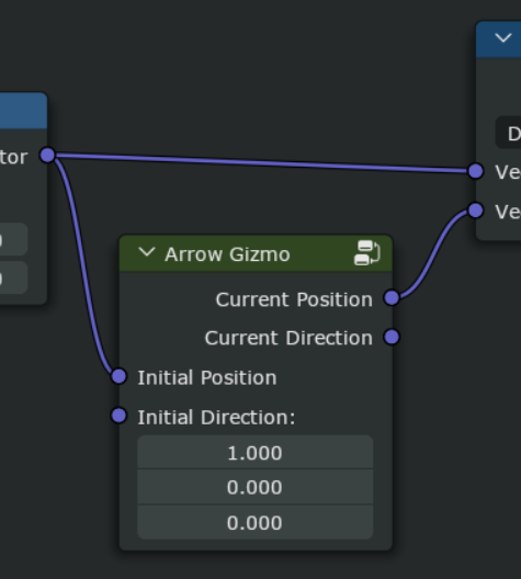
If it was done the initial position/direction in and current position/direction out, then I guess you could always use vector math to add offsets using let’s say keyframed vector inputs. You could either add the keyframed value before it goes into initial position, to animate the gizmo before it gets transformed by the user, or you could add it to the current position, to animate it after it was transformed by user.
I still just can’t figure out what technically necessitates the output being on the input side and requiring reverse direction flow.
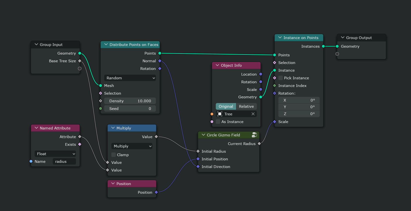
One thing to keep in mind is that we eventually want to extend the system so that we can show a gizmo e.g. for every vertex in a mesh. Imagine for example a forest generator node tree that places a tree at every vertex and there is an attribute on the vertex that affects the size of the tree. That implies that we want to be able to edit attribute values with gizmos directly.
Something that would draw a gizmo for each element in the field.
I guess my general point/idea is that I perceive the gizmo node as a very simple container for delta between initial parameters and current parameters, and what generates that delta are user’s gizmo interactions in the viewport.
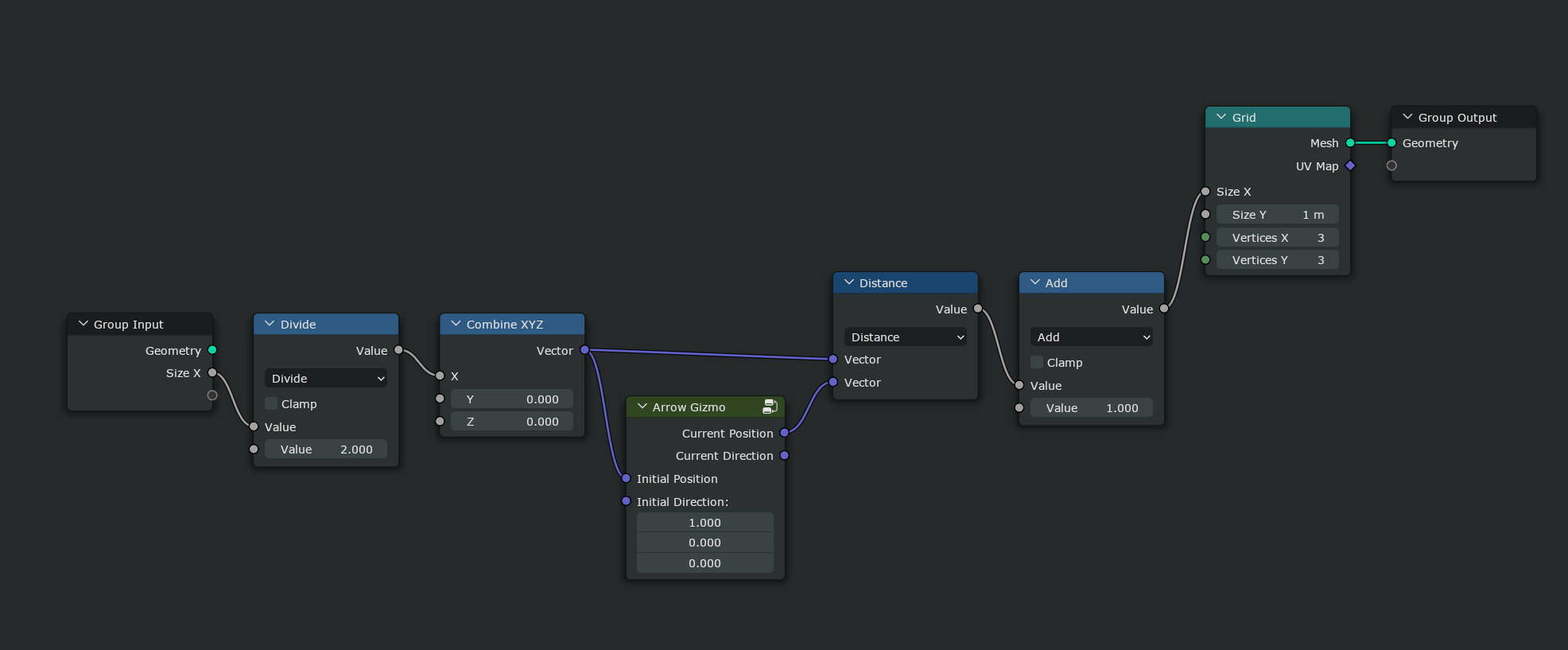
This would solve also the current issue of gizmo having this weird transform geometry type output, which has to be joined. In my case, I would assume you can simply transform the initial position if you want it to stick to some transformed space.
(EDIT: I removed the current position and direction outputs as I’d assume the circle gizmo is just for setting of radius, and can’t be moved/rotated.)
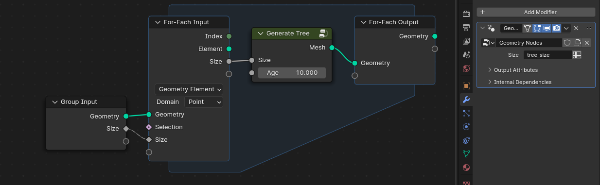
Well, essentially it can just work already without any extra gizmo specific nodes. It would require the work-in-progress for-each zone though to generate the individual trees for every vertex. The point here is that I can just define the gizmos in the tree generator node group and depending on how the node group is used I get the gizmos just ones or per vertex of whatever I want.
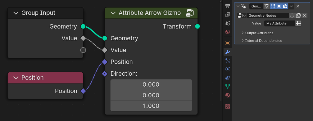
An alternative approach that we’ll likely explore as well is to have attribute variants of the gizmo nodes like in the image below. That would be more efficient for some simple attribute manipulation and when the for-each zone is not required anyway.
It would not solve the same problem. Sure you can always pass the transformed position to the gizmo node directly, that can be done in the current proposal as well, but that is not the point. The goal is to be able to create assets like the tree generator where the gizmo stays “attached” to the tree in the viewport even if the tree is moved somewhere else after it has been generated. The node group that generates the tree shouldn’t have to care about what is done with the resulting tree afterwards.
This makes perfect sense workflow wise, but would this be in any way incompatible with the previous example of single-value gizmo without reverse direction flow I proposed?
If this single value gizmo node adds one gizmo to the viewport, then if this whole thing is node-grouped, and put into For-Each zone, it would achieve the same effect but we would still not need to introduce the reverse flow concept?
Say you wanted to create a gizmo for the Angle in the Simple Deform modifier. I would expect to be able to edit the parameter itself, rather than some Delta Angle parameter separate from it. And that Delta Angle value would still need to bubble up to the modifier somehow and become a parameter there, since it can be different for every object that uses the same node group.
If you can’t edit the parameter directly, it just seems convoluted to me. Imagine if the same were true for object location or spot light angle gizmos. Surely users just want to edit the actual parameter, not some delta parameter?
Yeah, I guess that makes sense. My intuition still tells me the there must be some more user friendly way, but I will have to take some time to think about it. It’s true that if user set angle on the modifier input, which was then modified by the gizmo, in my solution, that new, gizmo-modified angle would not propagate back to the modifier input, so the angle would not match, which wouldn’t make any sense.
My little feedback would be to please put Gizmo category in Add menu in Utilities, or somewhere else. With asset libraries that menu is getting too tall and unmanagable, I have just 5 categories and it’s already too tall, no need to make it taller for couple of nodes
The color spacing on the reverse node line looks a bit like a display error, especially when it’s slightly not straight; perhaps if the gaps were smaller this would improve.
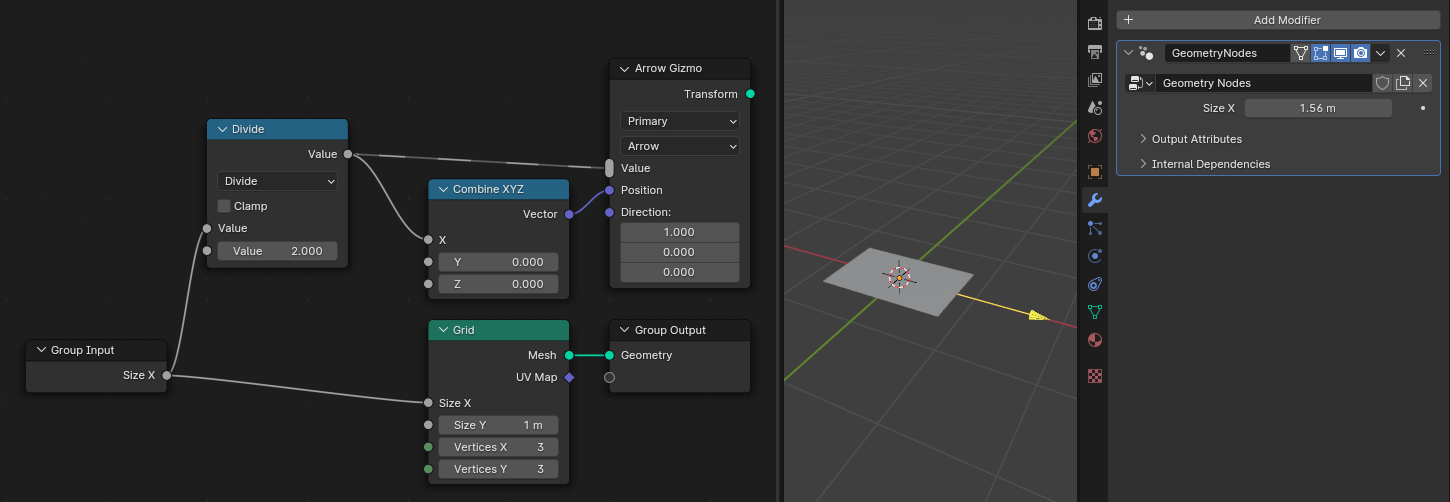
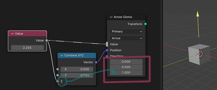
What is a good use case / necessity of having the Direction vector (section) in the gizmo, when the Combine XYZ is clearly designating the position to evaluate as Z? It’s like you’re having to tell it the same thing, twice.
Here is a Photoshop mockup of the alternative way to implement gizmos, without the odd backward socket. I described this in the previous comment. Is this comprehensive?
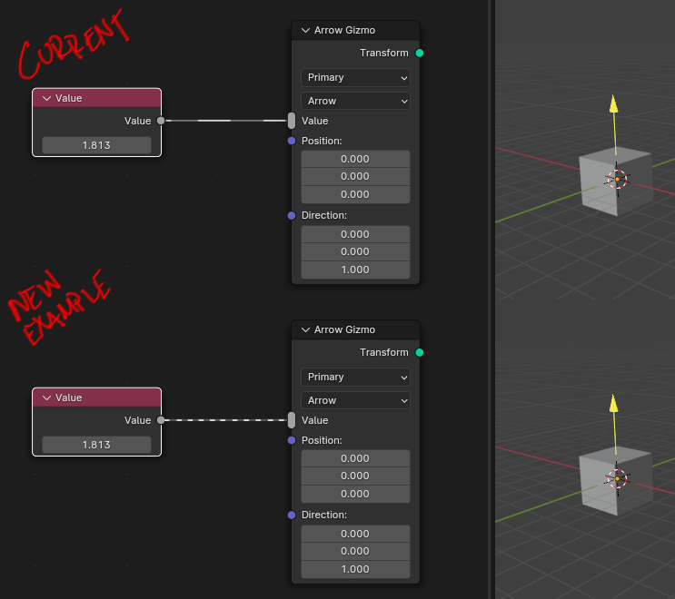
Here’s something that can go wrong:
What if you want a 1 meter movement of the gizmo to represent a value of 20 cm?
The Gizmo Display node needs some kind of a conversion multiplier float input.
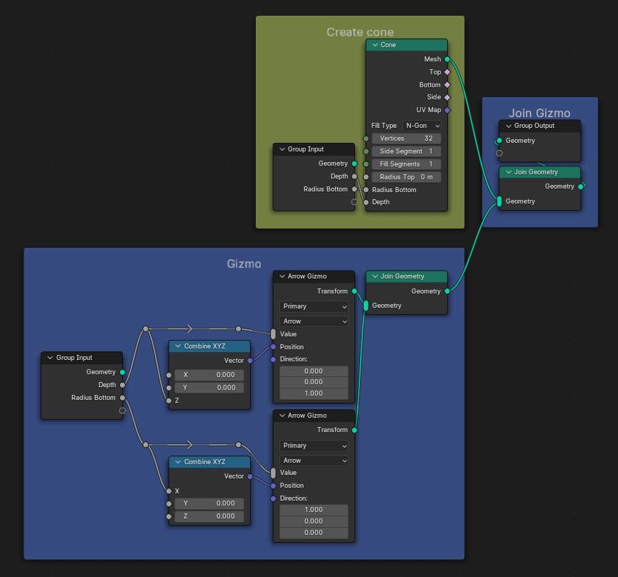
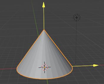
You may not always use the “combine XYZ” node with the arrow gizmo.
The arrow gizmo can drive a bevel width, on a bevel node, for example. That requires no “Combine XYZ” node, but you still need to define what direction that arrow is pointing…
This drawing is still experimental, but I’m happy to see suggestions. The spacing was intentionally a bit longer to not confuse it with field links. Note that the latest build uses a different drawing method altogether already.
I think I understand the proposal, but it doesn’t really strike me as being any more user friendly. Some other potential problems:
Can’t control the mapping between the gizmo movement and changes in the value (e.g. sometimes one wants that when the gizmo moves by 1 unit, the value changes by 10 units). ([EDIT: ah, I see you mentioned this now])
The screenshot doesn’t show the full picture. On a group node, every input socket that has a gizmo also needs this new gizmo index to be able to propagate it further.
Can’t see right now how the gizmo could e.g. control just the X value of a Vector input node, is there an index for every component of the vector, or can you only values in this special Gizmo Value node?
Can’t control the mapping between the gizmo movement and changes in the value (e.g. sometimes one wants that when the gizmo moves by 1 unit, the value changes by 10 units). ([EDIT: ah, I see you mentioned this now])
Solved by a multiplier float input on the “Gizmo Display” node. Can be called “Conversion”.
EDIT: or actually… It’s better to place the conversion multiplier, as a setting for the group input. This way, two inputs could be linked to the same gizmo, but display different values.
The “Gizmo value” node does not need such conversion settings, as math nodes can be placed after it.
Not sure I understand.
Each group input doesn’t have to have their unique “Gizmo index”. Two or more Inputs can be linked to the same gizmo, by using the same gizmo index.
In that case, all of them would have the same value, which can be adjusted by the same gizmo handles in the 3D view. However, the value may be cropped to Min and Max, as set for that group input. Those can differ for each Group input.
Also, if, on the modifier or the group node, one input is manually adjusted, the other would change as well.
If, in the node editor, there are two different values connected to two nodegroup inputs, but they are both linked to the same gizmo, that should simply not work (Returns error).
The Gizmo value is a constant, and cannot be multiple constants at once.
The Gizmo value would only be accessible from the Group input node (if there’s an input linked to a gizmo) or the Gizmo Value node. So, if you want to control the “X” value of a vector, you will need to connect one of those to the “X” value of “combine the XYZ”, and then connect that vector to wherever you want to use it.
Except the drivers error I mentioned, and some minor UX stuff, I think it’s good for initial release. It feels very comfortable once you get it. One thing I would target for 4.1 is auto keying, so that it can be properly implemented in animation and motion graphics workflows. (and non-view-dependant scaling, if possible)
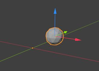
In the future, what would be good is if we could replicate the functionality of little squares on move tool gizmo, one that allows you to exclude one axis and move on remaining two. If you try plugging X and Y in the same gizmo right now, it just moves on both. It would be nice to have some way to have some sort of “free movement” and be able to drag gizmo around without being constrained to the axis.