Geometry Nodes Gizmos Feedback

The gizmo patch for geometry nodes is in a testable state now. It can be downloaded here.

This thread serves a few purposes:

  • Present the current design.
  • Gather practical user feedback to find potential problems with the design and implementation (also see the known limitations below).
  • Allow users to share their first tests and experiences with gizmos in a centralized place.

How It Works

The design went through a few iterations already. Here, I’ll only describe the latest design that is also available in the patch.

Adding a new Gizmo

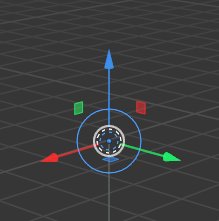
A new gizmo can be added by simply inserting a new Arrow Gizmo or Dial Gizmo node. After inserting a gizmo node, the gizmo will show up in the viewport immediately.

BkSw-UZNT

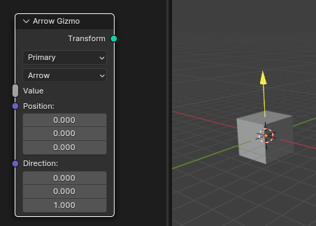
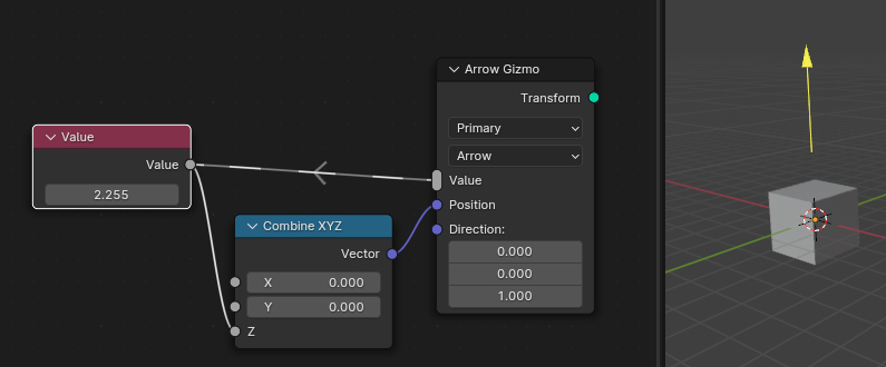
One can already drag the gizmo in the viewport, but it controls no value and always jumps back to the origin. For the gizmo to control a value it has to be linked to Value multi-input.

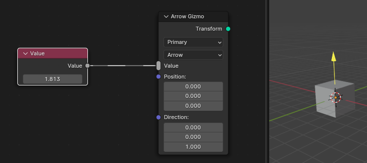
This may seem counter intuitive at first, and indeed, it introduces a new concept that is hinted at by the new link drawing style. This new link does not pass along any data. Instead its only purpose is to tell the gizmo node which value it should control.

When dragging the gizmo now, the value in the Value node changes, but the gizmo still jumps back to the origin every time. This can solved by actually making the gizmo position dependent on the value.

It’s important that the controlled value is to the left of the gizmo node, because that allows us to use its value to affect the position and direction of the gizmo. With gizmos, there is a fundamental two way dependency, where the value affects the position and the position also affects the value.

Since there is no actual data flow in these new kinds of links, only a very limited set of nodes is allowed to be used with them which will be explained below.

The limitation that only some nodes can be used with the Value input socket does not apply to the Position and Direction sockets. All nodes can be used to compute those.

Now let’s modify the example a bit so that the gizmo controls the width of a grid.

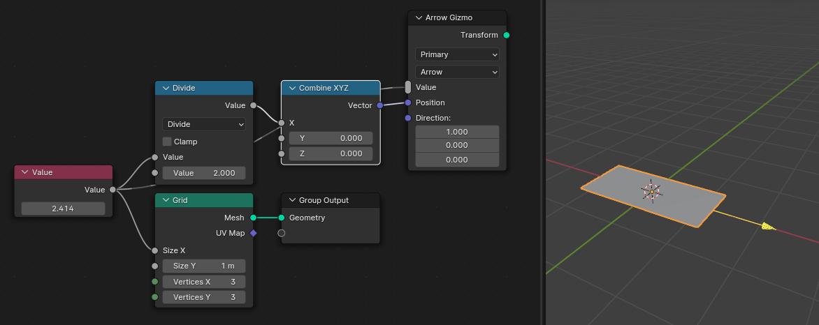
When trying this example, you’ll see that the gizmo does not stay attached to the grid when moving it. That is because by default moving the gizmo by one unit will also change the controlled value by one unit. However, in this case the edge of the grid only moves at half the speed.

To fix this, we have to tell Blender how movements of the gizmo are converted to changes in the value. Fortunately, this is easy here, because the Math node has special meaning to the gizmo nodes. The gizmo stays attached to the grid after simply connecting the Divide node directly to the gizmo node.

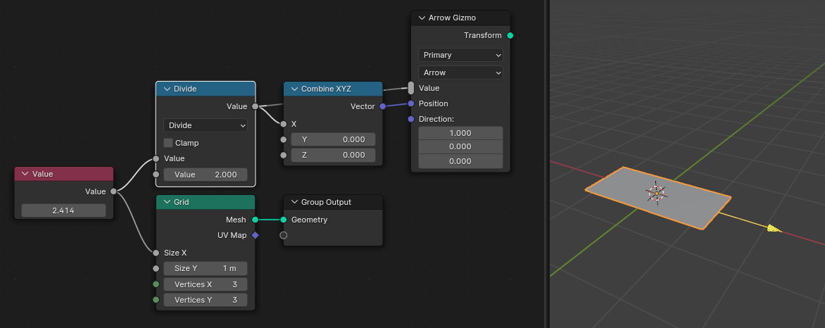
With this change, Blender can infer automatically that the value should be modified by two units whenever the gizmo moves one unit. Only the Divide and Multiply modes of the Math node have this special behavior for now, which is enough for the large majority of use cases. It’s also possible to use an Add and Subtract node, but those won’t change the mapping.

Gizmo Targets

We have already seen that gizmos can control Value nodes. This section shows the other kinds of targets that can be controlled by gizmos already.

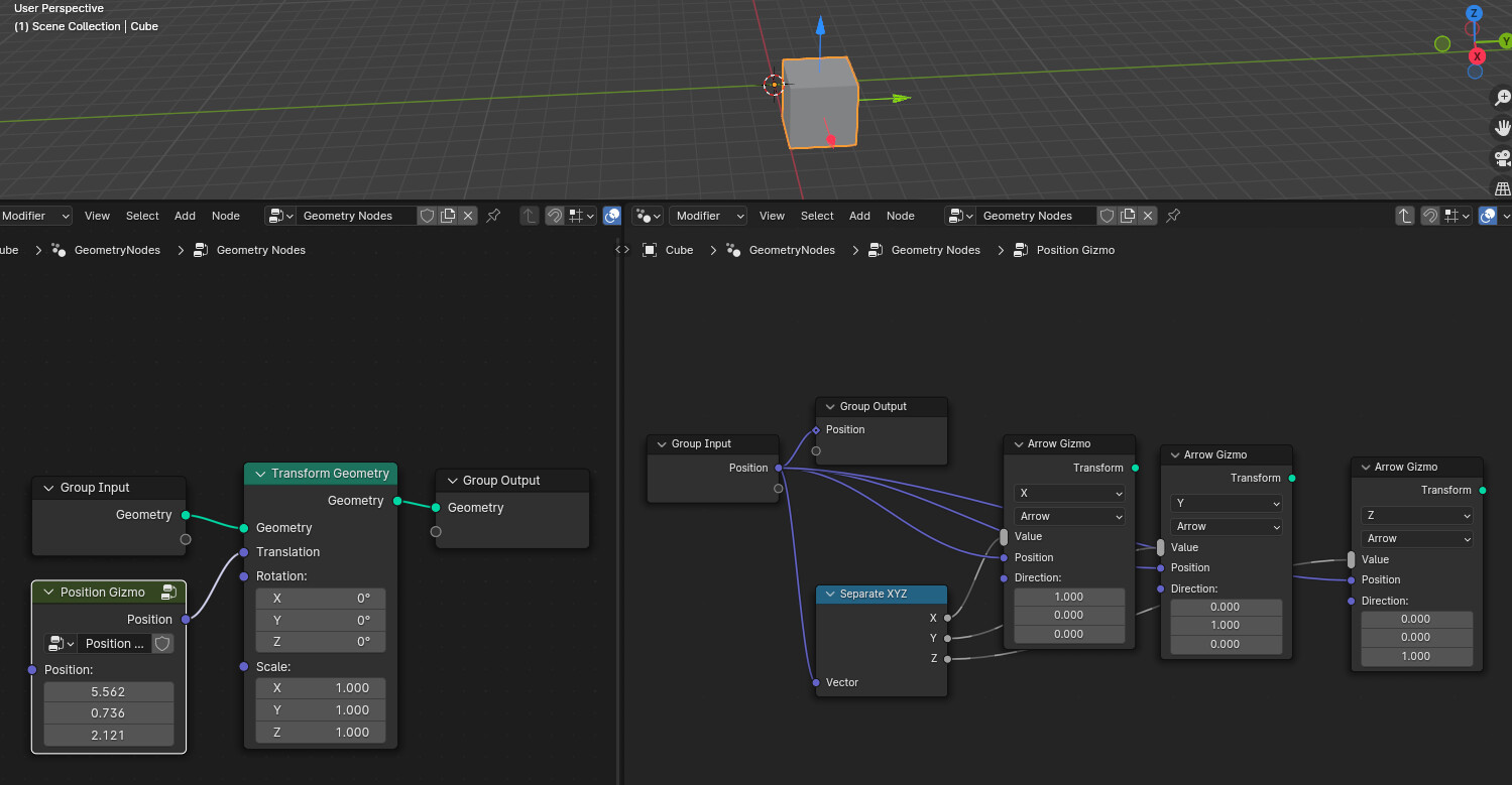
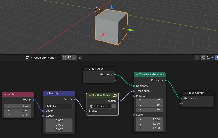
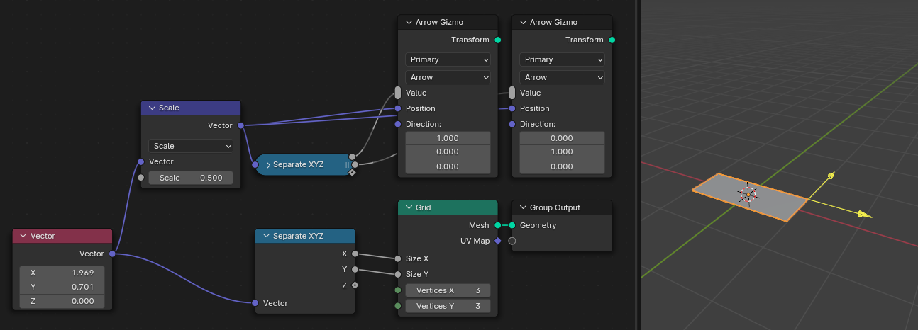
Just like the Value node, one can also use a Vector input node. However, since it outputs a vector and gizmos only control floats, one has to use the Separate XYZ node. This example also shows that the Vector Math node in Scale mode can also be put between a gizmo node and its target.

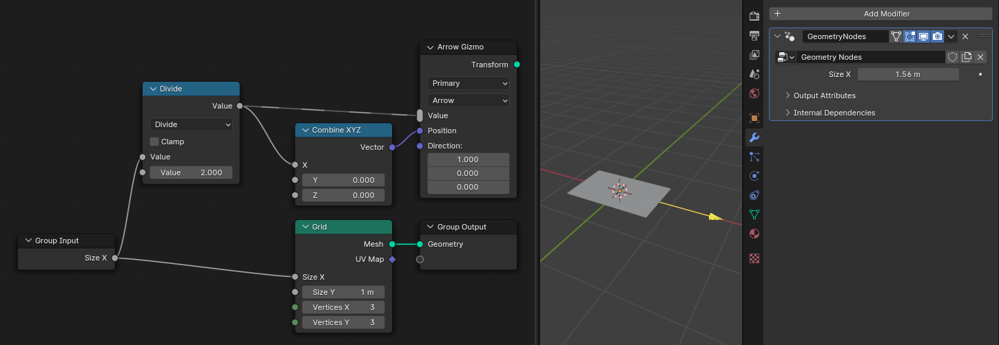
Besides controlling values that are hardcoded in the node tree, it is also possible to connect group inputs to the gizmo node. This allows creating gizmos that change modifier inputs.

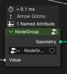
Gizmos that control group inputs can not only be used with modifier inputs, but also with group nodes. In the case below, the Grid with Gizmo group comes with a gizmo that modifies its input.

S1h-kw-VT

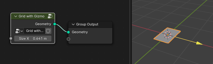
Note that in this case, the group node has to be selected. Otherwise the gizmo won’t be shown.
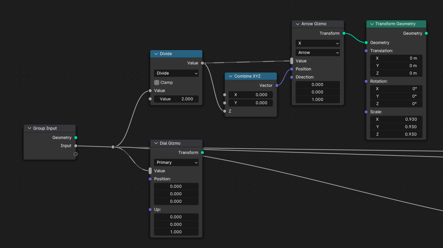
Gizmo Transforms

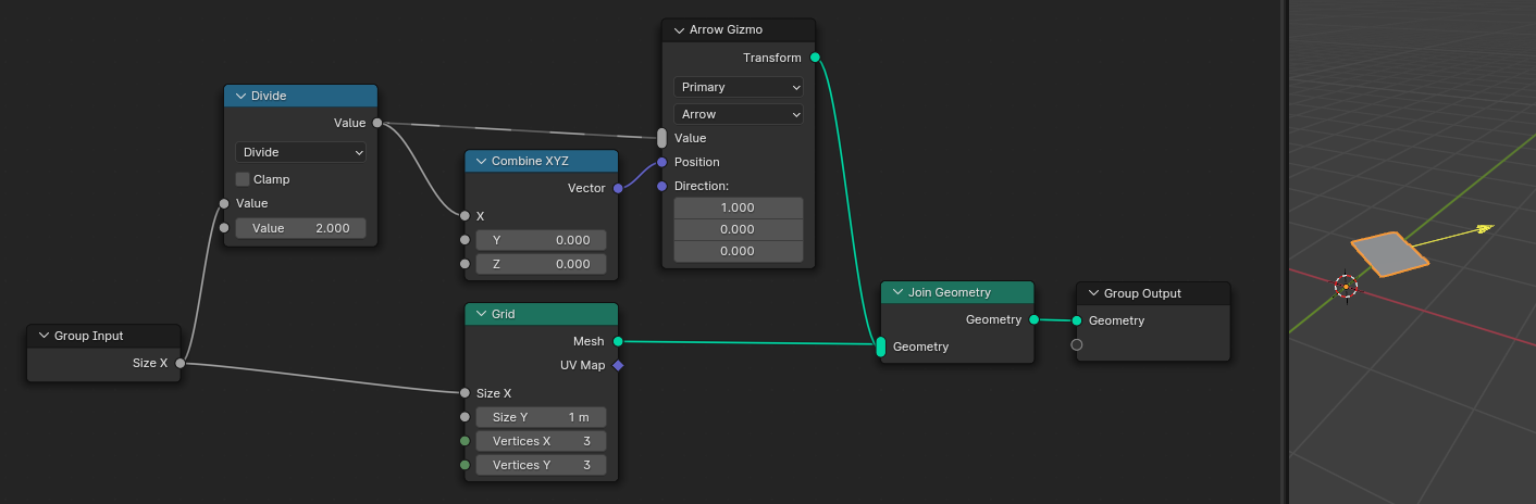
In the current setup from above there is a problem when transforming the grid afterwards. While the grid moves, the gizmo stays at its original location.

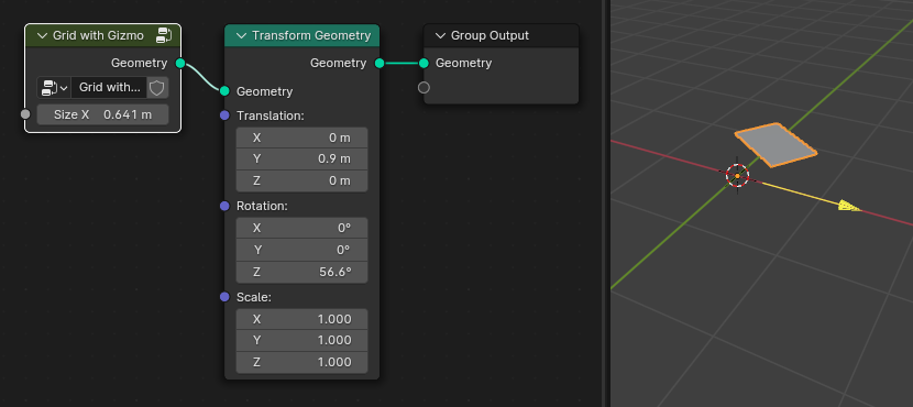
To fix this, the gizmo nodes have a Transform geometry output. This should be joined into the geometry that is controlled by the gizmo. Now, Blender has enough information two know that the gizmo should be transformed together with the grid. Typically, only people creating node group assets have to care about this. For people who use the assets, these transforms should work automatically.

Note that this only works within certain limitations, since Blender can not always figure out how changes to the geometry should map to changes in the gizmo transform. If there should still be a gizmo in such complex situations, it is better to just create a new gizmo and to compute its position manually.

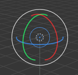
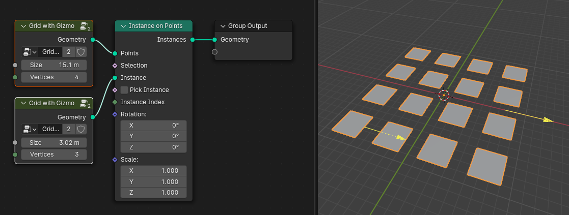
Gizmo transforms are also propagated to instances. In the example below are two grids, the size of each is controlled with a separate gizmo. For instanced geometry, the gizmos only show for the first instance by convention for now. The image shows both gizmos, because both group nodes are selected.

Multiple Targets

You might have noticed already, that the gizmo nodes have a multi-input. This allows a single gizmo to control more than one values. This can be used to e.g. build a gizmo that controls both the X and Y size of a grid while still keeping two independent inputs.

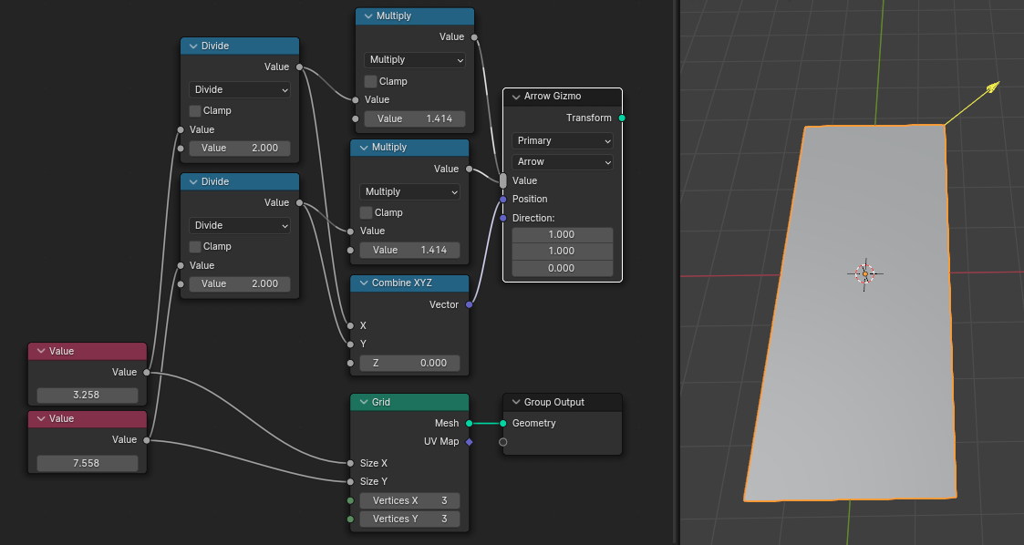
In this example, both inputs are changed by the same amount when the gizmo moves. However, it’s also possible to change them by different amounts.
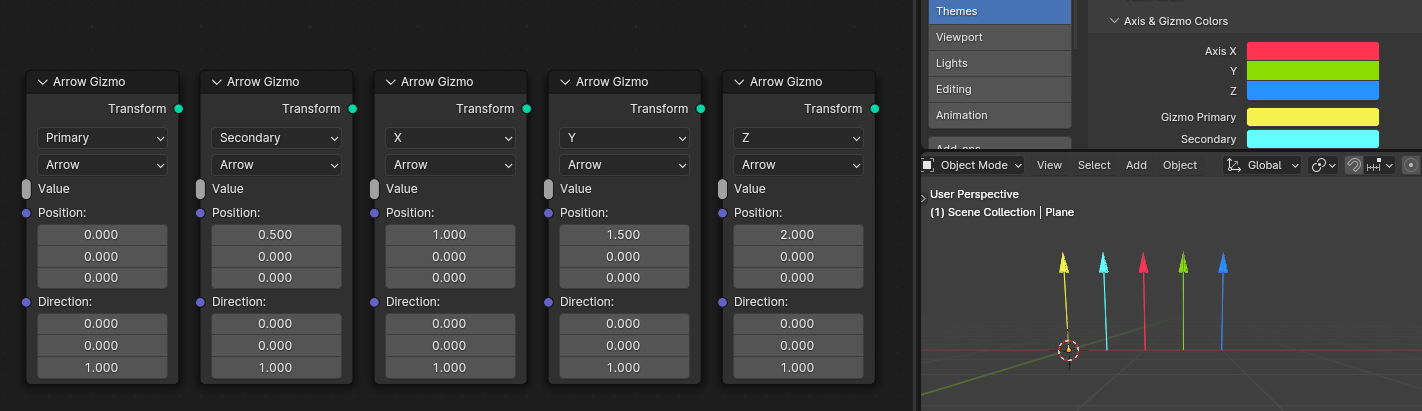
Shape and Color

Only a small set of gizmo shapes is supported initially. One goal to keep in mind is that gizmos of different node group assets should look and feel similar.

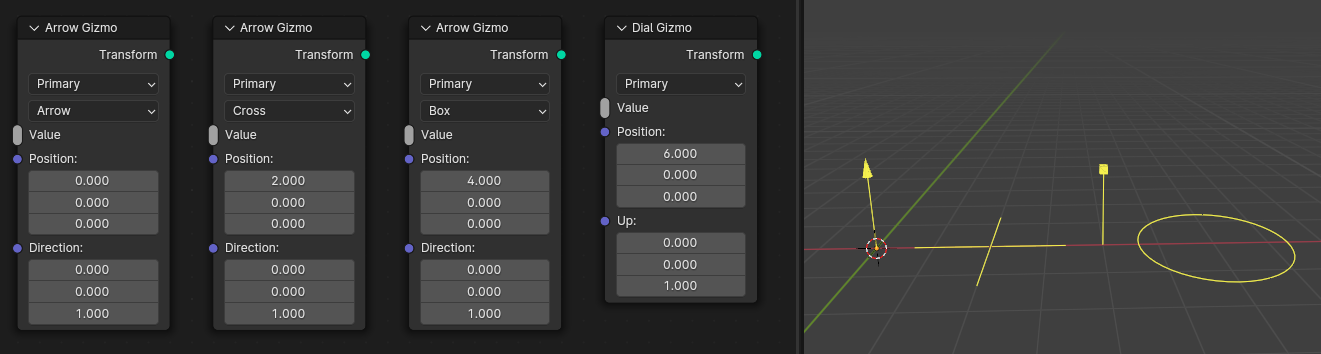
A similar constraint exists for colors. Currently, one can choose from a fixed set of colors that is used throughout Blender and can be modified in the theme settings.
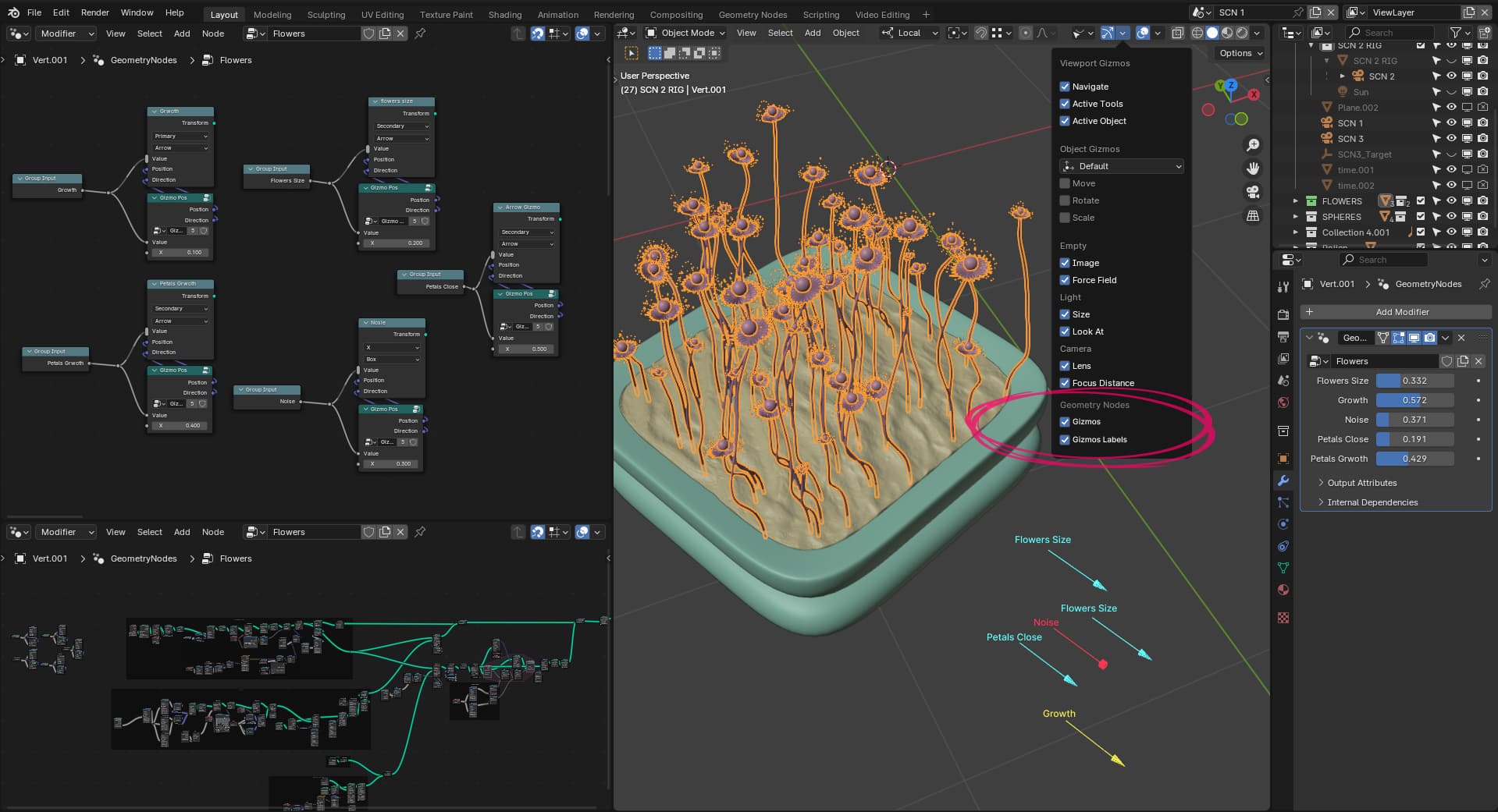
Active Gizmos

There are a few rules that determine which gizmos are visible in the viewport. A gizmo is visible if any of these is true:

  • It controls an input of the active modifier of the active object.
  • The gizmo node is in one of the open node editors.
  • The gizmo controls a value in a selected node in an open node editor.

These rules could be fine tuned with some user feedback. Manual control over gizmo visibility might also be added at some point.

Open Questions

While we are fairly confident in the overall design already, some UI decisions are still open:

  • How do we differentiate “normal” links and links that are used to connect gizmo nodes to the value they control?
  • Do we have to show that a node contains gizmos and if yes, how?
  • Do we have to show which input values have a gizmo and if yes, how?
  • Could Arrow Gizmo and Dial Gizmo be renamed to something else? For example, Linear Gizmo and Radial/Circular Gizmo.

Known Limitations

These limitations below are known and don’t need to be mentioned again. They are not fundamental limitations of the design but are intentionally left out for now.

  • Only a fixed set of gizmos shapes is supported that are widely used in Blender. Custom shapes are not possible.
  • Only a fixed set of theme colors are supported.
  • Can’t create a dynamic number of gizmos, e.g. one per vertex.
  • The base transform of a gizmo can not change while the gizmo is being dragged.
23 Likes

Thank you for this feature Jacque, and thanks for taking user feedback.

I’ll start with big things:

  1. Right-to-left behavior does feel very unintuitive and strange to get used to. I got the behavior after following your instructions and making my gizmos, it’s not too difficult, but definately strange. I don’t have any other ideas to propose so I’ll be content with this one if nothing else comes up, but if can definately be improved. One thing that I’m thinking is that I’m willing to give up ability to control number both as node input and gizmo, and only have it controlled by gizmo if that means left-to-right is used and I can simply plug in gizmo output in the value that I want to control. That behavior is worth the trade-off for me.

  2. I don’t see much value in current way links are drawn. In this example I have two gizmos controlling the same input, and links are only drawn up to the first socket they connect to, in arrow’s case it’s math node, in dial’s case it’s reroute node. What information does that give me? None at all imo. If I wanted to see where gizmos are I can identify them with header colors. I think either links should be drawn all the way to the input/value, or not at all.

  1. It feel weird that you need to use join geometry to change scale of the gizmo with Transform geometry node, because without it you simply don’t plug in that node into anything, it just appears, but to simply scale it you need to join it? And it’s not geometry either. They already have position and direction inputs, which are translation and rotation. I say just add Scale input in the actual node and remove Geometry output, would simplify things much more, and we’ll have less unnecessary links and nodes in our tree. (Especially with Dial gizmo, I see it as scaling gizmo, and there’s no way of scale it without joining it, it’s very weird and clunky.)

Also, Up input on Dial Gizmo is not good, I thought it was for moving it up at first and was confused. It’s just rotation. It’s better to call both Up and Direction inputs on both nodes Rotation (or Direction if you don’t want to confuse it with new rotation sockets).

Now to answer the questions in the topic

Absolutely yes, when node tree will have multiple gizmos I think it will be important to show that, so that I can quicky see which gizmo controls which group, and I’m saying groups because I think it’s obvious we will all create node groups for gizmos instead of doing math nodes every time.

Easiest way will be in the header, as overlay, similar to named attributes. With type of the gizmo and appropriate icon

New Project (1)

That would be very good for me to. Closest we have to this behavior right now is drivers. When input has a driver purple color is used to indicate that something else is controlling this value. I think new color will be needed to indicating that you can change the value directly, or by manipulating something else, in this case Gizmo.

Arrow is good, I like Radial more than Dial.

I don’t like gizmos at first instances, I know it can be changed by some calculations, but almost every time I would expect it to be in the middle of all instances, similar to how transform gizmos are drawn when you have median position as pivot point.

/

Lastly, you talked lot about limiting number of gizmos and colors, and I don’t want to push my luck too far, but some things would be good to consider.

First, we have Gizmo A and Gizmo B colors in themes, and it feels weird that those are not allowed. That’s what I use for my python gizmos. And having something called Gizmo in theme and not usable for actual gizmos will be confusing I think.
image

As for actual gizmos, I would be happy with just two more things: First, a box. Just a box wireframe, because I have some modifiers that would benefit from concept of Cages, as we have with regular modifiers. And second is vector gizmos, three arrows for three directions.
image
image

I understand they can be made with some tweaking and hard work, but out of the box those are the gizmos we will need THE MOST, we’re working in 3D software after all.

Some bugs or weird things:

  1. Gizmo gets covered by geometry. It should always be drawn on top, just like regular gizmos in Blender.
  2. When you disable viewport visibility of the modifier, gizmos are still there. You can’t get rid of them.
  3. Dial gizmo is very hard to control. It seems when you’re dragging it, closer you get to the top less effect it has on values, and you’re changing very small margings.
  4. Dial gizmo disappears when using it, arrow gizmo doesn’t. It feels weird when you can’t see what you’re changing.
  5. When I want to change strength of gizmo, I have to use Divide, istead of Multiply. Is that because it works right-to-left? Bit confusing.
4 Likes

Great feature. Did a quick test. One issue I noticed is undo ignores gizmo movements (and playing with the undo/moving gizmo I got a crash but it’s not clear yet which steps caused it). Other than that, it’s a bit confusing at first, but I think maybe with more pronounced visual hints (maybe something in the value socket and something a bit more noticeable in the wires), and some built in node groups for common gizmo sets this will be awesome.

Hey Jacques, this is super exciting. Got some concerns and ideas.

Linked Nodes
I find it odd that this encourages modifying values inside node trees directly. I think that won’t work well with the current LibraryOverride system. I think this needs to work with linked node trees to feel like a complete feature.

Multi-user nodes
If an object has a gizmo and the user touches it, it will affect all objects using the same node group. I think that’s very counter-intuitive.

Resetting to Default
It would be nice (vital and expected, even) to have the ability to reset the property driven by the gizmo to a default value, eg. by right-clicking on it, or pressing some key combo while hovering over it.

Multiple axes
Would be great to be able to author gizmos such as the 2-axis translation gizmo (the little red/green/blue squares), as well as the 3-axis, camera-space gizmo (The center-most part of all 3 transformation gizmos).

Idea: Store a transform matrix for each gizmo at the object level
Well, this may be a nightmare to implement, but I think it fixes all of the above.

  • Objects and their properties are supported by LibOverrides; Overriden objects are local, so any data stored on them will be saved in the .blend.
  • Objects are unique, so multiple objects using the same node tree can each have their own matrix for each gizmo.
  • You’re already storing properties at the Object level; Exposed modifier properties. This matrix could be one of those, except more hidden.
  • You can offset the matrix with transformation inputs on the left side of the node; This provides a customizable default value, and preserves a one-way data flow. The right-side of the node outputs the combined transforms of whatever static value is coming in from the left, plus the hidden matrix described above. This combined matrix is also where the gizmo is drawn.
  • A full transform matrix supports any number of axes, ie all 9 of loc/rot/scale x/y/z. On the node itself, you can configure what transform mode the gizmo should have, and restrict to 1 or 2 axes if you choose.

Hope this inspires some thought. Good luck, I look forward to this!

1 Like

This behavior is expected, and I think it’s the right approach. The values are stored in the value node. If you want to control the values per node group instance, you simply expose them as a node group input. That’s the answer we already have, and I don’t think there’s a need for a different approach just because values are controlled by gizmos. The ability to control node group inputs (i.e. values stored in modifiers) with gizmos is crucial here.

5 Likes

One thing that I’m thinking is that I’m willing to give up ability to control number both as node input and gizmo, and only have it controlled by gizmo if that means left-to-right is used and I can simply plug in gizmo output in the value that I want to control. That behavior is worth the trade-off for me.

That one is pretty much undisputable to me as it would limit the flexibility of the system significantly. It’s very important to me that gizmos are just UI for inputs that can also be modified by other means (e.g. procedurally).

Fortunately, the kind of gizmo that just acts as an input is kind of a special of the more general design shown here. For example, a position could be created like so (note that I just found a bug that the gizmo positions don’t update if you don’t actually use the position output of the node):

We already talked about the possibility that we ship this and potentially other similar node groups with Blender, and it seems reasonable. Feel free to build other node groups of this kind that could be bundled.

but to simply scale it you need to join it?

The scale is currently not really part of the gizmo definition because it’s view dependent. An additional scale factor could be added at some point if there are clear use cases.

Note that simply adding a scale input in no way removes the importance for the transform output.

I don’t like gizmos at first instances, I know it can be changed by some calculations, but almost every time I would expect it to be in the middle of all instances, similar to how transform gizmos are drawn when you have median position as pivot point.

It does not seem to make a lot of sense to draw these gizmos that apply to a single instance in the median of all instances, because then the gizmo is not “attached” to the geometry that it modifies anymore. During the workshop we already talked about other options (see the meeting notes) but couldn’t come to a final conclusion yet.

First, we have Gizmo A and Gizmo B colors in themes, and it feels weird that those are not allowed.

Yeah, we are aware of those colors. We decided not to include them at first because their name is a bit weird and does not convey any semantics (other than e.g. “Primary” and “Secondary”). We might add support for these theme options at some point, but maybe they should be renamed first.

As for actual gizmos, I would be happy with just two more things: First, a box. Just a box wireframe, because I have some modifiers that would benefit from concept of Cages, as we have with regular modifiers. And second is vector gizmos, three arrows for three directions.

For the second, see the image above. An ugly version of the cage gizmo can probably be build already. Would definitly be nice to add some more building blocks to be able to build a nice cage gizmo for sure. I think that still fits into the design nicely.

When I want to change strength of gizmo, I have to use Divide, instead of Multiply. Is that because it works right-to-left? Bit confusing.

Yeah that feels inverted at first, but is the only way it can work when using gizmos at a higher level. In the example below, we want the vector to change by 0.1 when the gizmo is moved by 1 unit.

I find it odd that this encourages modifying values inside node trees directly.

I don’t think it does, at least not any more than anything else we do. Like always, when you want things to be controllable outside from outside of your node group, at has to be group input. When working with linked node trees, you will only see the gizmos that are actually exposed (might not be implemented yet).

Internal gizmos are just a different way to modify values visually instead of changing sliders.

If an object has a gizmo and the user touches it, it will affect all objects using the same node group. I think that’s very counter-intuitive.

The response here is really the same as above. If you want a value to be constant with all uses of a node group, it has to stay local, otherwise just expose it as group input. The gizmos presented here are designed to make it very straight forward expose internal gizmos to the outside.

It would be nice (vital and expected, even) to have the ability to reset the property driven by the gizmo to a default value, eg. by right-clicking on it, or pressing some key combo while hovering over it.

Seems useful, but also sounds like a more general feature for Blender.

Would be great to be able to author gizmos such as the 2-axis translation gizmo (the little red/green/blue squares), as well as the 3-axis, camera-space gizmo (The center-most part of all 3 transformation gizmos).

The little squares are internally a drawing type for the arrow gizmo. I did not expose them yet, because the way they are drawn is a not unintuitive as an arrow gizmo. This gizmo shape could totally be exposed as well though.

I think Blender has some kind of drag gizmo that is dragged in screen space. That could be added as well, it will just be another gizmo node probably (one that controls a vector instead of a float though).

Idea: Store a transform matrix for each gizmo at the object level
Well, this may be a nightmare to implement, but I think it fixes all of the above.

I think this idea is not necessary given my response above. We shouldn’t have to store transform matrices for gizmos at all. That kind of goes against the idea that gizmos are just run-time UI that makes it easier to adjust settings.

4 Likes

Clear usecases for scale on gizmos for me would be if I have two dial gizmos at the same position, one controls A, second controls B. I need to quickly make one larger than the other, so that they’re not in the same position and cover each other.

I wonder why not allow color input for gizmos? Why is color constrained in the first place? Is that performance thing?

Made a test gizmo for squash & stretch modifier that always fits around the object and used scale for that. It’s nice but unusable right now because of all the bugs, disappears when moving, or behind mesh, no undo, and new one I noticed is that dial gizmo feels weird because when you move it up or left it changes value quite drastically, but when you move it down or right quite slowly. It’s quite messy and can’t get the hang of how it works and which direction I should be moving it.

2 Likes

Hey Jacques, I have only one idea.
Gizmos labels

With multiple arrows and restricted colors, it is hard to remember which arrow is in charge of which value.
Maybe labels on gizmos appear only when values are output in the modifier.
I know that the gizmo’s placement should suggest what action it will perform, but sometimes it will require a lot of nodding. With labels, we can make quick prototypes.

15 Likes

That seems reasonable.

As mentioned in the original post. It’s mostly a matter of maintaining common look and feel across gizmos in Blender. Also, some colors might look good for you in your theme, but look bad with another theme. In this case it’s good if the gizmo colors are also determined by the theme. This part is not really up to debate just yet. We can always add support for custom colors if it really becomes necessary. Currently it seems more likely that we would add more theme colors though.

Made a test gizmo for squash & stretch modifier that always fits around the object and used scale for that.

Looks nice. In this specific case I’d probably expect to use an arrow gizmo at the top of the geometry. Using the dial gizmo to control something that is not a rotation does not feel very useful right now.
Obviously, the drawing of the dial gizmo should still be improved so that it doesn’t just disappear.

Could be added, but likely not initially. One important reason for having gizmos in the 3D view is that their function is “obvious” based on their placement in relation to the geometry. As such, they shouldn’t need a label. Ah tooltip might be nice though.

While your example looks nice, I currently don’t see a good benefit for having these gizmos in the 3D view instead of just having named sliders in the sidebar which offer more functionality.

4 Likes

After playing some more, I came to conclusion that I just don’t like view-dependent scaling. They’re extremely weird, and make gizmos a nuisance, I find myself constantly changing active modifier so that gizmos disappear, because I expect to zoom out of the object and do something else, but gizmos are still in my face. They make it feel like you HAVE to use gizmos now, that’s what you’re doing, adjusting gizmos, and not like they’re helpful little things you can use if you want.

I also find it bad that I can’t make gizmos that fit exactly to my object. For example, I tried to create gizmo inspired by fillet gizmo in Cinema4D, it’s simply three box gizmos, but the whole point of that gizmo is that if fits around your object, and you can drag it to the point where you want your bevel to end. That is impossible now when gizmo is view-dependent.

But of course view-dependence is necessary for other things. A choice between them would be nice, similar to how you can choose whether sculpt brushes stay the same size relative to geometry, or relative to view.

2 Likes

Sounds reasonable to support customizing whether a gizmo scales dependent on the view, even if not in the first release. Do you happen to know if we have non-scale-dependent gizmos somewhere already?

2 Likes

I think sculpt brush cursors are only instance of that in Blender currently, but it’s necessary for some regular tools too imo.

Also, sorry to bring bad news but your patch broke some built-in gizmos

1 Like

Gizmo cage of camera?

1 Like

I think it may look prettier in some cases right? Like custom bone shapes…

The overall design is great btw, great job!!

(file >> 2023-11-15_well_gizmo_geometry_nodes.blend - Google Drive)

6 Likes

Good call. Also I checked Camera Limits gizmo (has to be enabled from viewport display) is also not view dependent and has exact same shape as crossed lines on arrow gizmo.

Also, force field and light probe gizmos are always same size, if they can be considered gizmos.

P.S. one thing that always bothered me because is view dependant is light size circle. It doesn’t actually show you radius which is covered by light, and gets in the way when you zoom out to look at full scene.

Cool and exciting stuff!

Small UI suggestion:

Why not use the direction arrow that is currently already used in Blender to visualize directionality? (it appears when two “dot” nodes are connected and the connection goes from right to left)

Otherwise, it would be impossible to guess what’s going on here without watching a tutorial and looking at the documentation.

4 Likes

Can’t reproduce this right now. Please check if the same issue exists in the main branch. Thanks for the report.

Yeah, we thought about that already. We might do that. It’s still not entirely clear which links should have this and which should not, especially when just using node groups assets that happen to contain gizmos.

3 Likes

So, the “Value” input on the gizmo node outputs the value backwards? If so, that is really weird and unintuitive. Maybe there’s a better way of doing this?

2 Likes

So, the “Value” input on the gizmo node outputs the value backwards? If so, that is really weird and unintuitive. Maybe there’s a better way of doing this?

The gizmo node does not output the value at all. It just attaches a gizmo to a value that is stored somewhere else. Obviously we have thought about other ways to do this over the last couple of months, all of which didn’t solve full the problem. Maybe just give it a try. :slight_smile:

Node groups work quite well and preserve left-to-right behavior when you simply connect input to output and plug that into something. I wonder if it would make UX better, especially for people who are coming to this blind, if Gizmo nodes outputted dummy value, that is just unchanged input value?

So let’s say you want to control grid size X with Value node, instead of doing Value > grid X and Value > Arrow Gizmo, you did Value > Arrow Gizmo > grid X. It would still function same way and change the value that is inputted, in this case Value node, but with dummy output you’d be able to have one link instead of two

1 Like