It appears that in my scenes, only when I go to super extreme colors I can see the difference.
In this case It looks identical to me…
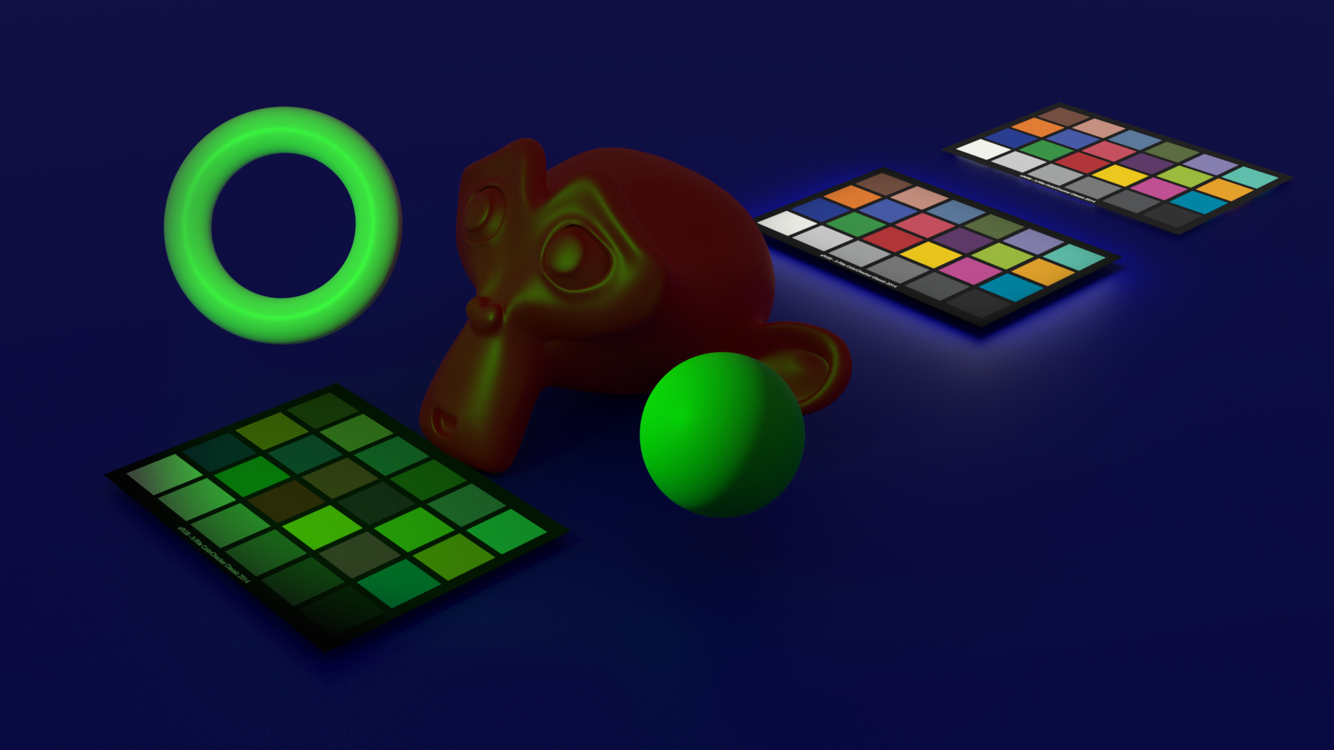
RGB

Spectral
It appears that in my scenes, only when I go to super extreme colors I can see the difference.
In this case It looks identical to me…
RGB
They are so close to being identical that I laughed  Great demo.
It looks you are doing very good with this, congrats! 
I hope this ends up in master sooner than later, I imagine this could bring other benefits in other areas
Just a question, I don’t really use Branched Pathtracing, does this support BPT or this only works with “normal” PT?
Also does this bring any benefits or ease to implement things like light tracing for fast caustics or other techniques, like GI cache?
Also, does this solve the problem @troy_s always mention about color management in Cycles?
Thanks!
Thanks, I appreciate it. It has been a long time coming but I’m happy to see some progress happening, although I can tell things are just getting started.
I hope the benefits are widespread, too.
It should, as in, there’s no reason it can’t, but honestly I haven’t tested it. If it’s broken, it is just a matter of me going and fixing the code!
EDIT: I checked, I’ve skipped it for now, once I have time to jump into BPT and understand how it works I’m hoping it’ll be a relatively straightforward change.
No, not that I can see. I’m not an expert on light transport algorithms, but I think that and spectral rendering are relatively separate domains. Instead of noisy white caustics, you can have noisy coloured caustics!
Colour management is a complex beast and I don’t think any one thing will ‘solve’ it, but I’ve been working with Troy on the OCIO side of this (which is a massive help) and I think there will be colour management benefits to come from this, especially in targeting modern (HDR, large gamut) outputs.
For pixel filters we have code like this in the kernel:
  int filter_table_offset = kernel_data.film.filter_table_offset;
  float raster_x = x + lookup_table_read(kg, filter_u, filter_table_offset, FILTER_TABLE_SIZE);
There we don’t compute any weight because it’s always 1.0, as the evaluated function and pdf cancel out. That’s ideal for importance sampling, and hopefully the same is possible here as well.
Otherwise, you would store the pdfs in a table as well and divide by them somewhere. I haven’t looked close enough at your code to see where the best place is.
That makes sense. Maybe I was misunderstanding what a PDF actually represents - it’s only the difference between the ideal distribution and the sampled distribution?
The use-case here is just to sample wavelengths weighted according to their perceived brightness, but the brightness of a wavelength is embedded in the CMFs, so I think I’ll need to come up with a curve to turn into both 1) the sampling weights and 2) something to divide by such that each wavelength’s overall contribution doesn’t change.
I’ll need to do a refresher on PDFs I guess, thanks for the tips.
@smilebags aren’t you doing hero-wavelength sampling? So sampling a hero-wavelength from a CMF or black-body-radiator or whatever wavelength distribution will also automatically return a sample at each of three other wavelengths (at fixed intervals?)… so the probability distribution gets convoluted (in a quite literally sense by the 4 Dirac spikes at those intervals) and thereby may lose significant noise reduction power. Then again… if the bandwidth of your Gaussian spectrum gets minimal, you get at least one sample for each 4 channels.
Yep
I’m not sure if I’m on the same page as you here.
My understanding of hero wavelength is that it is simply an approach of letting extra wavelengths ‘tag along for the ride’ on a base wavelength light calculation, since most of the time, most outgoing directions of a BxDF will have a non-zero throughput for a large part of the spectrum.
A bonus way of reducing noise when using hero wavelength is to correlate each of the wavelengths used such that the sum of their resulting XYZ locations doesn’t vary too much. This is done by evenly distributing the ‘child’ wavelengths over the wavelength dimension (0-1) of the integration problem.
What I’m doing after this is to skew the actual wavelengths sampled by this 0-1 range such that a majority of samples occur at wavelengths which have significant visual impact on the result, hence reducing noise.
I’m delegating the task of actually coming up with such a distribution to later, since there are all sorts of ways you could generate it, such as from the scene lights, a user-supplied curve etc.
This all happens completely unaware of any particular spectrum in the system (such as a gaussian spectrum) and narrow gaussian spectra are likely to be quite noisy until I can work on some more advanced sampling optimisations.
Brecht and Lukas have done quite a bit of work already to fix this in Cycles; Cycles was not colour managed! There are a couple of lingering issues, but last I looked, a majority were tidied up. It would be good if more people were versed in pixel management to be able to run it through tests to assert behaviour. Using rotated primaries is typically a very good way to test if management is working for example.
The other side of the coin is user interface, input, and output. For example:
The above still are not addressed in Blender proper, and focused changes need to happen there as a high priority.
@smilebags, we are almost on the same page I think. You do in fact mention the way you are going to solve my doubts: “skew… such that a majority of samples” and “perceived brightness”. So no worries. It is just that I expect that such skewing is very complex and won’t add much unless: 1) the perceived spectrum already features four humps or 2) when the distance between ‘child’ wavelengths is much smaller than the full sampled wavelength range which could put more samples near wavelengths about pure/saturated colors. Delegation / postponing sounds fine for now.
I think this is where we differ in understanding.
Regardless of the number of wavelengths that end up hitting any particular spectrum, the more values that are sampled in wavelengths that contribute a lot to the scene (green, vs a dim, almost invisible far-blue) the less noise there will be. That’s the goal.
The RGB render
2x GTX 1080: 0:42
Ryzen 9 3950x: 1:15
Combined: 0:32
I believe it’s simply weighting sampling based on luminous efficacy, which isn’t terribly complex at all. If it is something else, then perhaps.
That’s quite a time difference! I’ll have to look where that’s coming from, I imagine it might be my terribly inefficient hacks since I don’t know the language and code well enough.
The chart is an image texture?
I suspect the image colour space may be being set incorrectly here?
Blender by default uses collapsed GPU GL shaders to perform the transform, and in some cases that can yield quite different results from the more accurate CPU variant which the file save would do.
Curious if the first issue is as I suspect or something else. The second is also worth checking to confirm things are behaving.
I don’t see how it could be anything else currently. Safe for, like, each square being built from geometry, giving them an individual material or something. Of course, it’s not an accurate test since the spectral data of the colors can’t actually be specified in any way yet. They are going to be upsampled just like any other RGB value.
Me neither, but have to ask.
I suspect it’s an inappropriately described input image buffer.
It’s a jpeg, srgb… Used just as any other texture by default. I suspect the difference is still the same cause as the other issue. Saved file looks different from frame buffer in blender.
What colour space did you set the image encoding to, however? Image Viewer, properties. What is the encoding?
There were 2 options, srgb cctf and srgb gamma 2.2(i used the 2.2gamma cause it was much closer to “standard” transform of RGB cycles - in extreme values that is)