Thoughts and Use Cases for Passing Attribute Columns

This is just my thoughts following on from some of the ideas put forward in the Nodes Workshop.

I am a big proponent for handling the data in the node tree as lists (or attribute columns) as opposed to as attributes that are irreparably tied to the enigmatic “Geometry” socket. I think attributes are an excellent solution to sharing parametric data around Blender, especially as we gain more editors, and they also make sense for being able to send data long distance within a node tree where the noodles would clutter the view.

People have always talked about the issue with very linear node trees caused by the attribute workflow but a lot of the feedback that I’ve had through YouTube or Discord has been about how unreadable they make the logic and how slow it is to create a system. I do appreciate that the Attribute Processor’s task is to change the workflow to allow nodes to be used as in shaders with visual connections that allow for reading the logic and therefore no typing out attributes. I would maybe argue that if the processor is being added to cover a UX issue, perhaps the solution would be to roll out that workflow paradigm more widely. The Attribute Processor still has the issue that it can’t create new geometry, it only manipulates existing attributes on existing geometry which makes its utility in a true parametric modelling setting somewhat limited.

A disclaimer; my main experience comes from Grasshopper (for Rhino3D) and Sverchok (addon for Blender) and a little Animation Nodes (addon). I have used Geometry Nodes fairly extensively but I am coming to it from tools that are more focused on lists of data. I am also only an artist with effectively zero understanding of limitations and impediments under-the-hood with developing this kind of system.

For ease I will just illustrate these use cases with Sverchok although I’m not suggesting to copy the workflow, just to show simply common modelling techniques that benefit from columns sans geometry.

  • Use of position data from one mesh being used as an input for another mesh.
    In this case, the initial circles have 24 vertices and so 24 quadratic splines are generated.
    The Knot1 and Handle inputs are receiving a list of 24 vectors and Knot2 only has a single vector and so it is repeated to be common for all resulting splines.

  • List Levels can be taken advantage of to be able to differentiate seperate elements within the same set
    In this case we have one list of vectors coming out of the final node but we can see in the text editor that we have 3 discrete objects each containing 4 vectors. This is exceptionally useful for being able to join and separate elements as needed.

  • Curating Edge Flow
    Little bit of a messy example but using List Shifting, Sorting, Shuffling etc can all offer the artist more authorship over the modelling process.

  • Creating selections and masks
    Here Suzanne is getting a mohawk by masking faces by their area and then using that mask on the extrude separate node. This example could be as easily done with Attributes but in more complex systems the branching helps readability as well as using the data in other parts and even other geometries.

  • Analysis data from one object can easily be used to control any aspect of another
    Here an initial list of random vectors is used to create a cubic spline. Along the top row a circle gets lofted along the spline to create a pipe surface (not disimilar to the current Curve to Mesh node in Geo Nodes but we’re able to maintain the superior parametric features of curve / surface workflow).
    Along the bottom, a curve frame is generated from the initial spline object which is essentially a transform matrix. That matrix is applied to the vectors being output from the Torus primitive node. As none of the order is altered, the edges and polygons don’t fail during this transform.


    Alternatively a list of float values can be used to analyse the transform matrix at multiple positions along the curve. An artist is able to maintain absolute control and use a manual list input or else generate a list of values (or control it by analysing another part of the model).

  • Readable Logic
    There are some benefits of the attribute workflow but legibility is not one. The challenge of revisiting an un-commented node tree, especially if you’ve used and reused burner attributes. It’s not really feasible to understand what’s going on because string nodes will be connected to many different sockets, controlling different data at different points.
    For example this is the UV Sphere node from my Geometry Nodes Toolkit (I made a custom node for it to work in extra attributes and functions such as index, U and V limits etc) and the logic is unreadable to anyone who doesn’t already know how to plot the points of a UV Sphere.


    Compared to this example of a freeform waffel structure where I can still go into the (un-commented) node tree and understand what each collection of nodes does 6 months on.

  • Choosing specific elements
    In this example the nodes off-screen to the left have created an irregular hexagon grid. The grid is exploded to create 85 discrete faces with unique vertices. This changes our list of vectors from 1 object containing 216 vectors, into 85 objects, each containing 6 vectors. We’re then able to selectively choose an object by its index.


    I’m then able to use a manual list input to separate out the vectors for the left and right side of the shape. Two lists of 3 vectors allows me to create 3 different horizontal Line curve primitives from which I can evaluate the 3 centre points. These vectors then are moved using another list input to shape the panels manually. The nodes on the right take each set of 3 vectors and create an arc, aligned vertically, which is then used to to create the actual surface which can be instanced on the face centres of the initial hexagon grid to create the panel array.

I think one of the current problems of Geometry Nodes is the idea that geometry needs to be made and then modified. Any float list could be combined to create a vector list and any vector list could be read as vertices and the length of a list should be able to be changed on the fly based on the initial inputs rather than being restricted to what geometry is already existing. Especially relevent when doing this sort of entirely node-based workflow is having some method to mesh later on in the process. A large part of the process is going to be manipulating vectors without altering edge flow, in which case the other parts of the geometry can be inherited from the earlier stages (much the same as the current GN strategy with controlling the position attribute). For these more parametric workflows there’s often more of an emphasis on using curves and surfaces as opposed to meshes as you can easily evaluate points, trim, extend, join etc without losing the accuracy of your system. Compare this to using mesh objects and if you want to maintain accuracy you need extremely high resolutions right from the start. The parametric integrity and workflow flexibility of curves makes them an ideal tool in these systems.

I think there is more merit in the attribute workflow when Geometry Nodes is being used to create a complex modifier similar to Macros or Actions in other software. Even with the list workflow you can still take an input geometry, put it through some transforms, edit parts of it and then eject an updated geometry at the other end.

This rock formation takes a guide geometry as input, distributes points, separates into 3 levels, creates edges between levels 0-1 and 1-2 and then evaluates multiple points on those edges. These vectors are then used in Geometry Nodes with points to volume and volume to mesh. Several displacement modifiers, remesh, subdiv and displace later and it goes back into Geo Nodes for foliage. If this was all within Geo Nodes then that suddenly becomes a “Rock Formation” asset which allows artists to feed in only guide geometries and output macro rock structures for environments. I can imagine a similar utility for architectural panelling and types of common structure like waffel structures.

It feels like attributes should be used more around the edges as an artist when needing to get or set, the actual bulk of the handling of data and logic should be something visual and artist-friendly. There are many more use cases but legible logic and being able to intuit your way to an answer are two solid votes for list / attribute column workflow in my opinion.

19 Likes

To be honest, to me it feels like an exachange. We would certainly gain a significant workflow improvement compared to current state of GN nodes, which as you correctly describe is usually unreadable and very slow to create, especially when one has to create tons of arbitrarily named intermediate attribute variables.

On the other hand, the Sverchok workflow seems way too alien to how procedural modeling is handled in other mainstream procedural DCCs out there, so if users were to migrate from them to Blender, or use them in the same pipeline as Blender, it’d come with a lot of pain of just how different the workflow mindset is.

I’ve made a few proposals on how to improve the workflow in the original GN thread (with screenshots):

The idea was to simply replace that grueling attribute wrangling in form of a long, linear attribute math nodes by a simple node trees similar to ones people are already using in Blender for years in material/shader editor. I really don’t think that the Attribute Processor node is a fortunate way to go about it. It’s building an infrastructure around a technical limitation, so instead of solving that technical limitation, it will actually become more entrenched in the workflow.

But I ultimately crashed into the same issue you describe: “attributes that are irreparably tied to the enigmatic “Geometry” socket”. So I started co

But then it hit me. Why not just let us construct attributes using nodes the same way we can do in shader editor, like this for example:

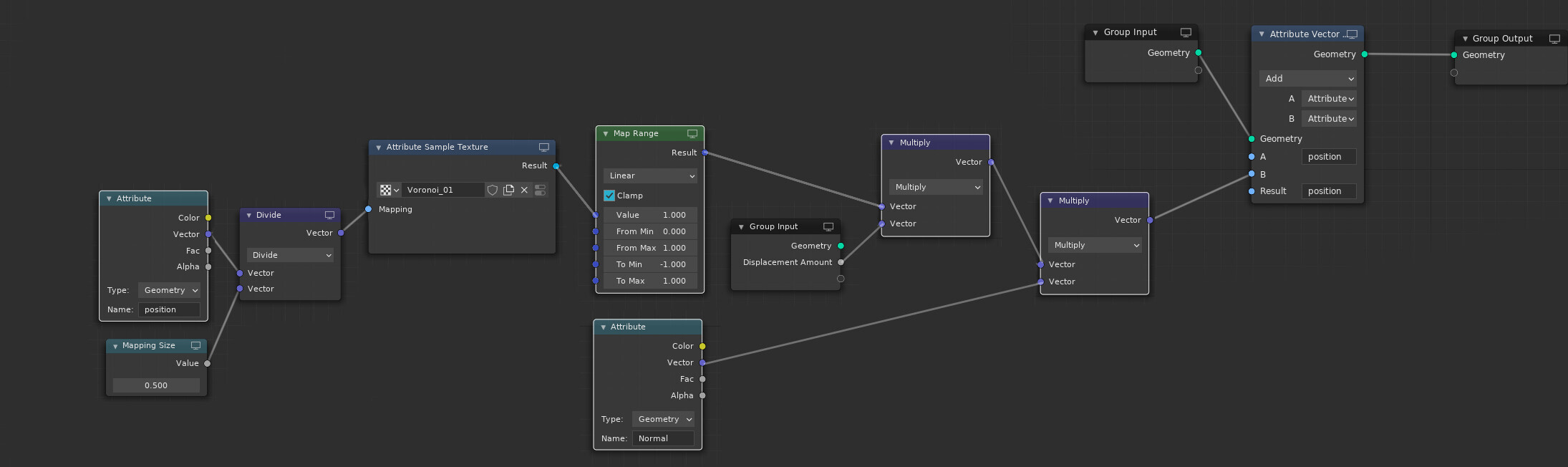
So that if you create any arbitrary node network, which outputs a bool/float/vector/color math function in the end, not a geometry data, then plugging it into any node which inputs and outputs the geometry data would automatically, implicitly tell GN “Hey! Let’s run this math function used as an attribute input on each element of the geometry input.”:


That way there would not be a need to “get” any geometry data to feed the purely mathematical function with. It’d be implicit, and simple.

The only somewhat technical obstacle I see is that if you wanted to feed your math function with some attribute, if you wanted to have automatically populated attribute name list, like with nodes that input/output geometry, you’d have to walk upwards in the node tree to the geometry node and fetch the attributes from there. Which could be tricky if the result of that math node tree is used in more than one geometry nodes.

But at the same time, this is not an unsolvable problem. We have somewhat solution to that kind of problem already. For example, in material editor, there’s UV Channel node which takes UV channel name as a string, yet you can apply this material to multiple objects with UV channels of different names. So I’d be fine with a limitation of not having attribute autocomplete list in non-geometry nodes and the attribute-name-getting non-geometry nodes failing (returning 0) when plugged into geometry nodes which don’t have an attribute of a given name. It’d still be worth it if we got a freedom to construct the math node networks in GN the same way we do in material editor.

I am sorry if this clutters/derails your very elaborate and carefully crafted post. The point I am trying to make is that we do not have to give up the attribute workflow in order to make it faster to use and more readable. At the same time, I do agree with you that the Attribute Processor node doesn’t feel like a right solution. It feels like turning a lack of design or a technical limitation into a feature. What I propose is to have “attribute processing” as a first class, top level feature, not decoupled away in some special node with a limited feature set.

3 Likes

Sverchok is more or less a parallel to Grasshopper which, at least in Architecture and Design, is the industry standard. Blender does generally target animation so that might be a moot point.

I think we have a similar approach here. The idea of one main set of nodes that can equally process single values as lists of values rather than an Attribute duplicate node for every standard node.

As soon as you start working with lists you do need to have nodes specifically for managing the lists themselves for sorting, pulling/inserting elements etc.

This is your displacement setup shown in Sverchok and you can see how readable it is similar to yours (for parity I’m ignoring Sverchok’s texture displace node):

Not at all! This is an open discussion and I don’t think our thoughts differ by much. I agree that attributes are valuable methods of storing data on geometry which makes truly interconnected systems throughout Blender possible. I also would like to see more of an artist-minded logic approach to the nodes actually used within the system, more similar to shaders, rather than hiding data in attributes which breaks the “visual” part of visual programming.

Edit: You made a point about issues arrising from geometry not having the named attribute used in the system. This is only really an issue for specific things like Vertex Groups or UV Maps. A visual connection based system calculates all of its new data analytically from the input so it’s only information needing to come from outside that could trip it up which is the same as the current system.

1 Like

Hi,

could you please explain a bit more what happens in the captures ? I am not familiar with Sverchok. From what I understand, you are mapping position attributes between different geometries as per their index, am I reading this right ?
In short, you’re trying to come up with a solution to work with arbitrary lists and decouple them from the geometry ? Just trying to reformulate this with my words, bear with me…

Cheers,

Harien

1 Like

Yes essentially the index controls what interacts with what.

For example here the line at the top has indices 0,1,2,3 for each vector and the bottom list of vectors has been shifted by one so 0,1,2,3 output from the List Shift node is actually 3,0,1,2 compared to the original list.

The UV Connection node is joining vertices where U is joining the edges on the line and the V would be joining between the two lines. The data can be visualised something like this:
Line 0 = 0,1,2,3
Line 1 = 3,0,1,2
“U” is data within in object in a list
“V” is different objects in the list

Relying on controlling indices allows things like this to follow more of a logical building up of processes.
In this case a Plane primitive is generated on the bottom row. I want to bend it up so I add a simple deform node. I want an array of these panels so I use a Matrix Apply node taking the positions from another grid up top. This is now generating 400 panels.
I want to change the amount each panel is bending so I control the angle of the simple deform with a float list coming from what is essentially an Attribute Sample Texture node. The sample texture node is sampling the same grid points that the panels are positioned on and the indices correspond 1:1 so everything matches up nicely.


To do the same process with what I imagine the current Geo Nodes workflow would eventually provide. There’s a lot of writing out attributes when the nodes could just output the data directly. The at-a-glance logic gets muddied with things like the attribute transfer nodes. It’s unclear if the transfer is going to the whole mesh instance/island or just to some verts and so unclear if the Bend would be assuming that angle attribute is per vertex (which would break the panels) or per panel.

I’m not saying lists in SV and Grasshopper are the pinnicle and all other systems should be shunned. I know the big H uses a different system. I’m just wanting to illustrate some potential hurdle the current system will face moving forward and how an “Attribute Column” (or list) workflow handles those kinds of tasks.

3 Likes

Readable Logic - on that point i agree that is a problem. certain nodes in the future will be long with 8 or more settings at least like the raycast node currently is. Future simulation nodes/hair nodes might have to be squeezed down to simple versions just to fit on the screen. I would prefer to put all settings of the selected node on a new panel that users can leave open on the right hand side. This does make screenshots /sharing nodegraphs online harder to follow. However this gives major advantages if you also can attach written notes under each node describing the thought process (since more space is available) I have been learning Houdini recently so just giving another viewpoint. The quick mockup below puts the selected node (raycast) settings on a panel on the right.

2 Likes

I think supporting lists in geometry nodes is a perfectly reasonable thing to do. Having nodes to get/set attributes of a geometry and nodes that deal with lists in general can be very useful. However, I also think that this should not be our only solution to the node-tree-linearity and temporary-attribute-names problems.

Passing all attributes around as separate lists does not seem to be a viable solution when you don’t know all the attributes while building the node tree. Building reusable node groups that keep existing attributes intact seems difficult. At least I’m not sure how it should be done in a good way. How would an extrude node work, that just works on lists as the one in Sverchok that should keep all attributes on the geometry intact?

The idea mentioned by @LudvikKoutny is actually the foundation of the “fields” proposal I mentioned before sometimes. We’ll try that as well to see if we run into any major issues.

Fortunately, lists and fields don’t really conflict with each other. They could benefit from each other quite well actually.

@Joze that is a separate problem that we are working on as well. See T87009 and T89140.

8 Likes

I agree somewhat with Erins sentiment.

Context

I have used other software (now both EOL) that had both “everything nodes” and a bit of AN, Sverchok and now GN a bit. I have also gone through big H’s workflow, but not used it in a pipeline. Everything else I have used in a pipeline, other than GN (haven’t mastered it yet).

The software that are now EOL, sadly from corporate decision - had workflows that were much more user friendly than current solutions with GN, even young un-inexperienced me could pick it up. Both of the UX’s had concepts that attributes or “data” could be linked and passed on from node to node, up and through and around tree levels all through the GUI. There was no need to write any connection, not in nor out of the logical and visual flowgraph. I could do it all in the GUI. Visual programming at it’s best.

I personally think if you are to develop a system with node graphs and visual programming, EVERYTHING should be able to be used with mouse only, meaning you can run sliders, click and tick boxes, select drop downs, plug in sockets, link sockets, link out sockets and thread sockets throughout the tree - even with “data” or what we call attributes. This is where GN needs finessing.

The current workflow with GN has a bit of a disconnect when it comes to data flow, mainly because data jumps between the visual flow graph with no visual connection at all between nodes - only logical written connection (invisible in the UI). Which means for visual artists like myself and others, picking up GN (and the big H) becomes very difficult to grasp, and also kinda makes the whole node graph not adequate when it comes to visual programming, teaching and breaking down.

I picked up Sverchok in a single project under client pressure, mastered it and made it work just from some limited guidance and lot’s of intuition with the noodles and sockets to make rocks - I never used it before. I even could scatter with slope in mind.


I am confident I can do this in GN, but I know I will have to write attributes, get and set/select them within nodes only, and somehow use them in a disconnect logical plane of thought that doesn’t quite exist in the GUI, other than the “execution” green line that tells me “this data flow from left to right”. Though I could be biased, I have yet to master GN even with client pressure - where my use of it is resorting often to only scattering (something that can be done without many attributes sometimes - thus linear “execution” data flow - in to out flow logic)

Recommendation:

What I recommend as a UX, is the ability to be able to thread data flow (attribute/data socket flow) between the GN “execution” flow (geometry socket flow).

Attributes has a String/Data In, but no String/Data out. This make a disconnect in the logical visual flow graph. The UX means we have to logically map out data flow in our heads, but can’t see it in the visual node editor. This is not a optimal mature workflow/user experience (UX), nor a visual guided user interface (GUI).

I recommend, if there is an attribute socket in with data in, there needs to be an attribute socket out with data out. And… to understand how the trees work, the green socket (Geometry) should be understood that it is an “execution” socket, run the data stream through the trees with the connected green socket flow, or else it won’t execute (as we already know).

I can’t stress it enough, we aren’t working flow graphs from the big H, we aren’t working flow graphs from any other software… we are making visual flow graphs in concept, which means even attributes/data needs flow and graph representation. Writing/selecting attributes and getting/setting data only inside nodes as disconnected attributes/data concludes there is no visual “flow”, and it’s not a graph - meaning the visual node editor and visual programming currently implemented not the ideal UX we discover and need when it comes to Geometry Nodes with data flow UX requirements: input data, process data, output data then execute the chain in the tree accordingly.

Issue at hand

Right now it’s… input execution line (green) to establish ready set data sets, get/set data in nodes (attributes, not clear what we are doing when we define attributes) from a disconnect (no visual representation other than words), process disconnect data through an execution line (no visual connection between data nor attributes), set data only within nodes (no flow, disconnect) and output “data” as if it were an execution logic chain (green geometry out) but then told it’s the data flow, creating confusion on first use, disconnecting the visual tree from the logical data flow. It clearly is not a simple logic for a visual programming flow graph… It’s a technical pipeline, yes, but not an artistic pipeline, as there is no visual flow graph of data and attributes. Only an execution In - modify by getting, modifying and setting data within single node and disconnect logic of getting/modifying/setting - then an execution Out. it is not clear if we get, modify, set data AND start, run, end execution at the same time or not.

Solution to the UX

It could be this: start execution line (green thread In), get data (attributes), link, set and modify data through execution line (visual links between nodes and data flow - any data/attribute type sockets; and visual links for the execution flow - green sockets), set final data and output data at end of execution line (green thread Out). Get Data / Start Execution, Modify Data / Modify Execution, Set Data / Finish Execution.

Get, Modify, Set - on a data/attribute UX level is what we need. The blue sockets are “getting, modifying and setting” directly in single nodes, but there is no visual flow graph to understand it - also there is an ironic paradox, we loose granularity because of this. Allowing to flow attributes and their data “out” of data processing nodes helps to understand data flow better, and also opens doors to granularity - and this would be an excellent improvement to the GUI and smoother/easier UX to using/understanding attributes and their data in the flow graph.

Pro’s and Cons

Issue: There would be more clicks because of more node linking.
Solution: another hotkey to link all sockets automatically. Atleast now we can see everything visually, and we only would need to click and press one hotkey instead of write many words over and over and over again, hundreds of keystrokes at the end of the day, when it could be a few swift mouse movements.

Issue: What about writing and setting/getting attributes? Will we still be able to write/create new attributes?
Solution: Show a GUI for attribute types/lists where you can drag and drop them into the graph (outliner with new view, or properties editor, or any animation socket/data block drag and drop), and it will add two get/set nodes for you. A blank Get Custom Attribute and Set Custom Attribute nodes would be used for custom attributes if you need to make a new one. And the ability to use “Get Attribute” nodes dragged in or set manually by “Set Attribute” node flow can be used many times anywhere in the tree. It can also be Set anywhere any time in the tree, as long as it has it’s place in the Execution Flow Graph (geometry socket line).

TLDR

You’ve done amazing things with functionality - now it’s just finessing the UX, the user experience. And this requires… fulfilling the goals of a node editor for programming 3D stuff: visual data flow with a mouse only based GUI = make attributes and their data also flow visually in the GUI along with the “execution” Geometry lines.

11 Likes

Or better yet, remove the “Geometry In” and any green line to the “Geometry Out” will run dataflow logic. Rename Geometry Out to “Execute” and now we know any green line will execute the tree and data flow, and we can optionally get the mesh data, or create mesh data then set it when we execute it on the tree out. This is assumed that attribute and data flow can now also happen between nodes.

I know I am late to the party, so my feedback is maybe a year too late - but hopefully it helps out!

I know what software you’re referring to, but for clarity, do you mind explaining what “write connection” means here ? = connecting sockets ? or writing attribute names ?

Writing a connection is the current behaviour. In node A you write “scale” and in the next node you also write “scale” to make an attribute connection.

Desired result is… You just get scale from a “get” node and link it through the chain through the modifying nodes. No invisible written connection or link, but an actual socket and noodle.

Thank you @Erindale, artist feedback is really valuable when we coders are fumbling around with new concepts. The lack of constructive geometry tools is something i struggle with every time, and end up doing needlessly complicated mangling of some existing primitive.

I’ve started implementing my own proposal for attribute sockets a little while ago, and i am cautiously optimistic that it can work. I want to push it a little further, migrating most of the attribute nodes to the new style, and then see if the geometry socket can be eliminated from most nodes as well. Then eventually moving to “pure” lists wouldn’t be such a big step any more, at least that’s what i hope to prove.

@LudvikKoutny’s idea about defining the geometry context only where it is actually needed could work nicely for that. With the attribute sockets the geometry tends to run in parallel to output attributes, making it mostly redundant. Geometry inputs would only really be needed on complex nodes or “output” nodes, and could be back-propagated to inputs.

We’ll see where this is going. I’m happy there is some consensus though on simplifying the visual language of GN and opening up new possibilities.


11 Likes