Making an Add-on for Precision Drawing Tools (CAD)

OK, here we go, add a vertex at a precise location with my PDT tools; Command was na10,,15 (new vertex at global 10,0,15), then extrude it thus:

Command was ei3,137.65 - Extrude 3m at 137.65 degrees to horizontal.

Then select both vertices and extrude thus:

53

Command was ei3,47.65 - Extrude 3m at 47.65 degrees to horizontal.

Simples! took longer to write the first sentance here than to do that. I might change the ‘i’ letter (meaning direction) to something else, if you feel this would be better, just suggest something that is not already taken…

That would be nice…

Now I am off to my airfield to carry on with the 3-year inspection of my glider, the poor old girl is 56 years old and like Precision Modellers, needs a lot of love. :small_airplane:

Cheers, Clock. :cocktail:

1 Like

I had an idea that I am pusuing:

Any guesses what I am up to? I have made a start, but I need sleep now.

Cheers, Clock. :biohazard:

Cool, I’ll have to give it a spin soon. See how this compares with Rhino :slight_smile:

1 Like

@jesterKing I’ll try to get the latest version uploaded to my website today, I need to do some more checking.

Meantime, I have done this:


I started with a cube and scaled it as shown

Here we have the Pivot Point shown as the axis drawn in red, green and blue.

This can be used to rotate the selected geometry, in the view plane about an axis normal to your screen, by the specified Angle amount.

It can also be used to scale the geometry by three factors about itself. The pivot point can be dislayed by clicking the PDT Pivot button, ESC removes it. The size of the pivot point is determined by the Size value, e.g. 2, or 50mm, etc.

You can also put the Pivot Point at the cursor location, there are so many ways to set cursor location, I thought this was the best method to place it other than by scrubbing the location boxes, or inputing values for X, Y & Z, which you can also do of course. Moving the pivot point does not move the geometry, there are also so many ways to do this in Blender & PDT already.

Cheers, Clock.

EDIT:

I have just put it back as it was by using reciprocal values in the scale boxes (type 1/ in front of what was there):

The thing that I imagine, seeing your precision gui … is that it would be nice to have a sort of double way of drawing …
Directly on the 3D view, by dragging the cursor and the objects to be drawn, and inserting parameters through the gui, but with the condition that both modes are correlated, interact interactively, so as to be able to draw in an approximate way an element on the 3d view and then go to adjust the modified parameter in precision …

I know I know it would be a good challenge to do something like this, and it would probably be necessary that the tool has a sort of database that remembers the history of all the actions and the parameters modified for each single vertex, as well as a system that recognizes, for example, a rotation with respect to another vertex or object, or a displacement of a vertex in an absolute way instead of delta, etc … etc etc …

the idea is very basic (I’m thinking about it at the moment and trying to imagine how it could work), and probably not entirely understandable, but I hope it gives an idea.

it would need prediction and contextual algorithms with respect to the last actions performed. :see_no_evil:

1 Like

I have absolutely no idea whatsoever how to do this! I took me ages to work out how to draw the Pivot Point so it responded dynamically to changes in the Location input boxes. This is something I will have to spend a lot of time researching I think…

I have used dictionaries in the past to store history and then give the use the ability to scroll back though them. It might only be necessary to hold the last set of selected vertices (as a list of vertex indices maybe) and the position they were in, so that step could be undone and replaced with a precise version. This would be messed up though if the last step was to add a new vertex. Hmmm much to ponder on!

I could try using invoke() functions, but the variables are used in many operations, I would need to know which one to associate them with, can’t see a way to do this just yet, I will think on.

Cheers, Clock.

EDIT:

I have just remembered that on 1 August of this year I did not even know how to make an Add-on, how times have changed and how quickly. :mermaid::footprints::penguin:

5 Likes

:grin:

however it must be admitted that the idea is interesting and the challenge as well.
guitarnana

1 Like

I’m looking forward to the latest version!
You’ve mentioned you plan to reorganize your web page but in the meantime a comment stating something along these lines would be nice:

N-panel version: Animation Nodes is not required; Enable Prefs->addons->3DView:MeasureIt.

This does not sound like something you would want to do with a Python based add-on where you have a limited number of options available in terms of data, performance, and memory management. Take the interactive gizmos part for example, one issue I kept running into when trying to make these with Blender’s Python API was needing data that was only accessible through Blender’s C code. You can find creative work arounds for some of these limitations, but they tend to make for complex and hacky code.

Maybe I am misunderstanding your idea though.

1 Like

Done that! Yes, that was a good idea, I hope to have the new version uploaded soon, I need to add some options to move the pivot point via the command line.

Cheers, Clock.

For Better, or for Worse, I have uploaded this new version to my Website here:

I will complete my bug checking, but if anyone want to give it a spin and let me know their thoughts, I should be most grateful. There is a simple sample Parts Library file there, feel free to add your own parts to it in the normal Blender way. I will look at being able to upload objects from your current blend file to the parts library, currently I do not know how to do this.

Cheers, Clock. :penguin::joy:

EDIT:

I have noticed that this; bgl.glLineWidth(3) doesn’t have any effect, I must look at why, unless anyone wants to tell me…

2 Likes

I am getting p****d off!!!

Here is my code to draw the lines:

shader = gpu.shader.from_builtin('3D_UNIFORM_COLOR') if not bpy.app.background else None

    def draw_line_3d(v1, v2, rgba, context):
        scene = context.scene
        coords = [(v1[0], v1[1], v1[2]), (v2[0], v2[1], v2[2])]
        batch = batch_for_shader(shader, 'LINES', {"pos": coords})

        try:
            if v1 is not None and v2 is not None:
                bgl.glEnable(bgl.GL_LINE_SMOOTH)
                bgl.glLineWidth(scene.pdt_pivotwidth)
                shader.bind()
                shader.uniform_float("color", rgba)
                batch.draw(shader)
        except:
            pass

Every other piece of code I can find on the 'net and all the references in API Docs says that bgl.glLineWidth() sets the line width, it DOESN’T on my Mac.

Can someone test my Add-on on windows and tell me how thick the Pivot Point lines look, they should be 3 (I hard coded it to that) on the version I uploaded to my website. Or, can someone tell me what I have done wrong here, or is it a bug :bug:, or is it not supported anymore. I am using official release 2.8 for MacOs.

Cheers, Clock.

That’s not supported any more on Mac (OpenGL driver related). It’s barely supported on the other platforms as well.

1 Like

yup, best not to rely on legacy GL features. a fragment shader that takes line thickness as an input is fairly trivial.

edit: here’s a good discussion on doing it with a geometry shader, which is even better:
https://forum.libcinder.org/topic/smooth-thick-lines-using-geometry-shader

1 Like

D’Oh! I had hoped that was not the case as this was the only method I could find that uses Python…

I have read that and have to say that I did not understand how to use the shader part, although I understood the geometry calculations.

As I understand things I need to replace my use of the bgl, and probably gpu libraries with something else. My knowledge does not allow me to write my own shader, so is there an alternative for Blender with some examples of how to replace the code I posted earlier? Do I have to write my own, or use someone else, that I then have to ship with the Add-on?

Is there somewhere I could get hold of some python code that draws the gizmos, or some other 3D View Graphics for example to get me started?

Sorry to seem thick, but his is outside of my knowledge base…

Thanks for the replies and cheers, Clock.

1 Like

Oh dear, senior moment I think. :older_man: What you youngsters have to bear in mind is that when you get to my age this will happen to you also. :rofl:

I think I may have a solution to this:


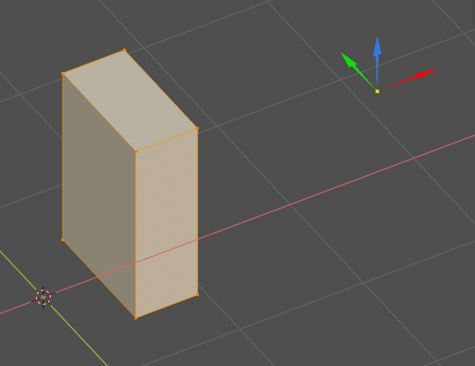
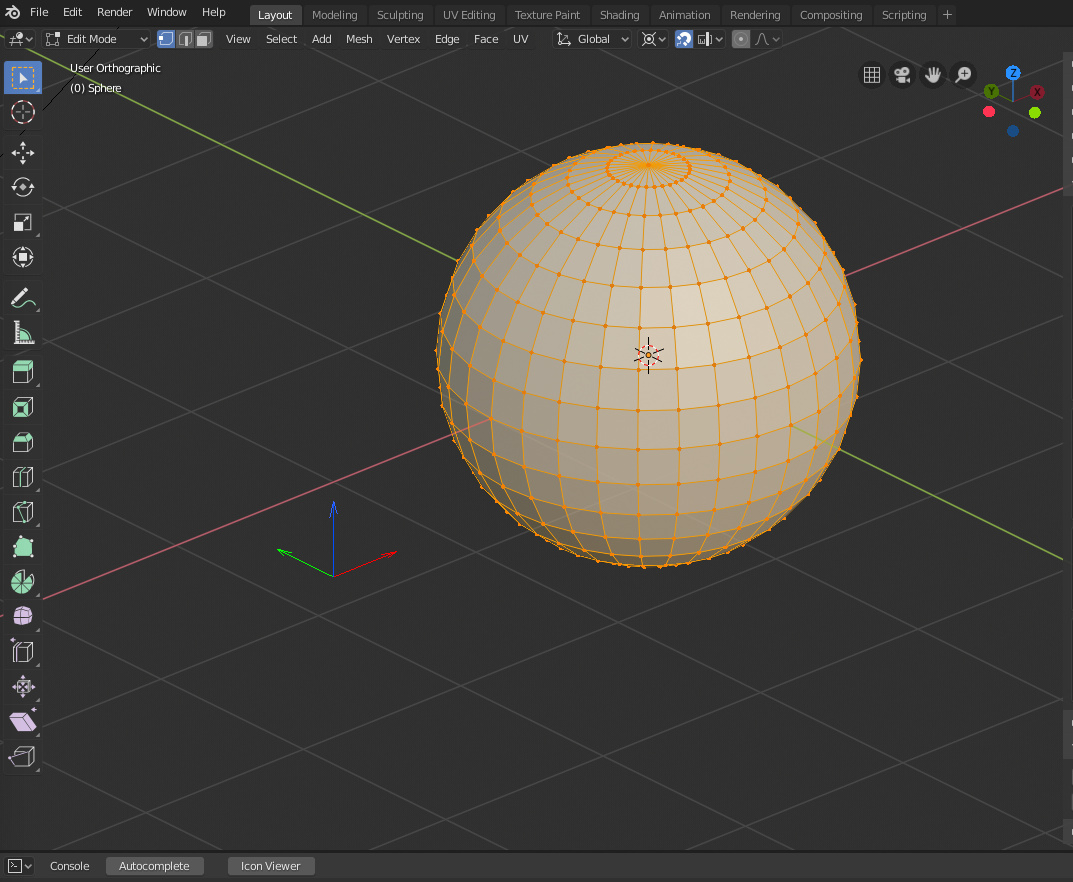
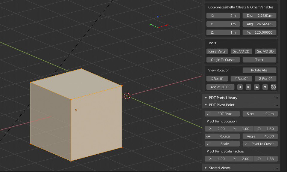
Pivot Width set to 1.


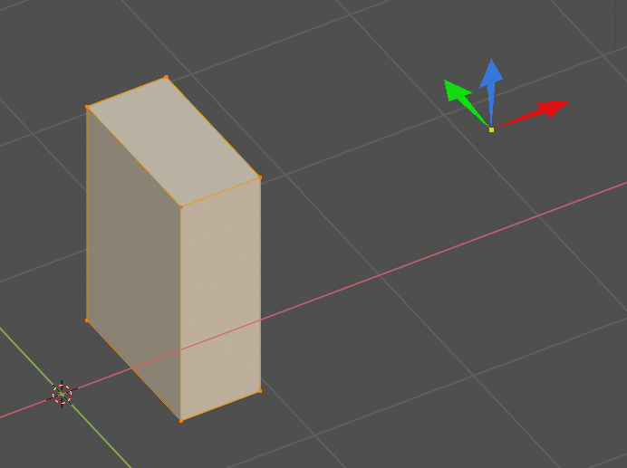
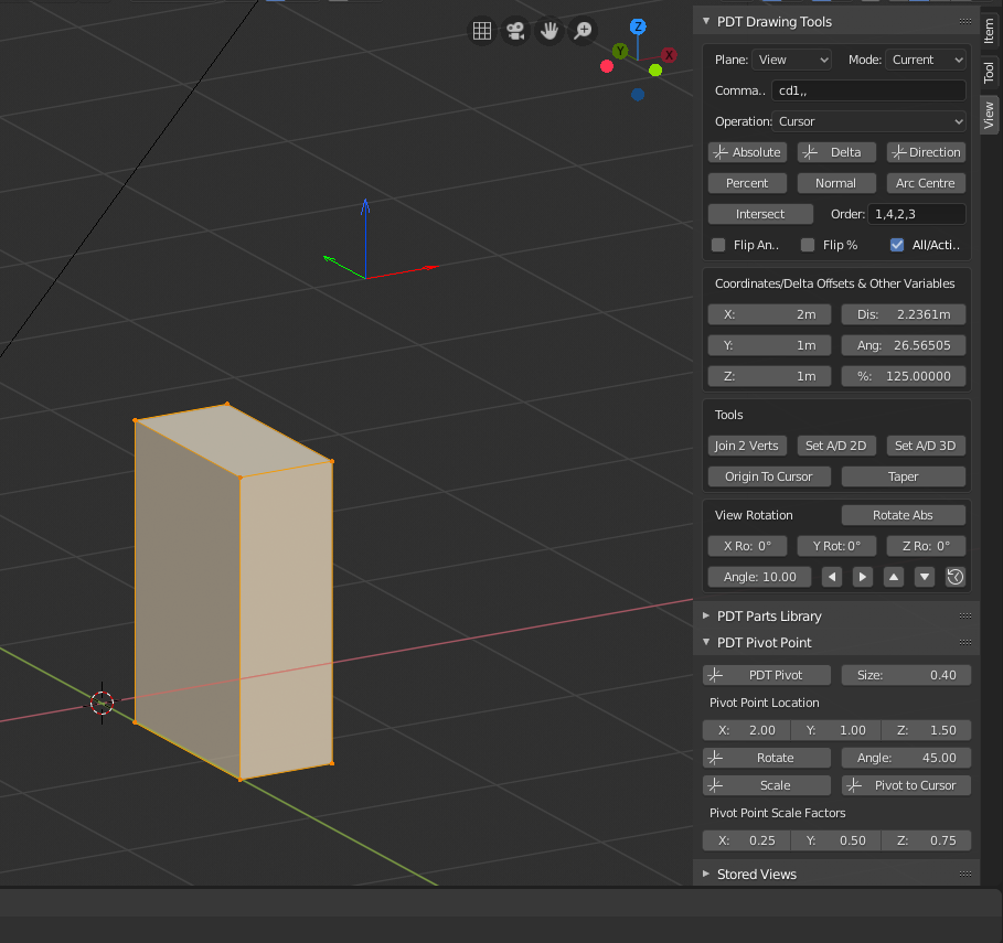
Pivot Width set to 5.

Code (you will probably tell me this is crap and also how to improve it):

shader = gpu.shader.from_builtin('3D_UNIFORM_COLOR') if not bpy.app.background else None

def draw_3d(coords, type, rgba, context):
    scene = context.scene
    batch = batch_for_shader(shader, type, {"pos": coords})

    try:
        if coords is not None:
            #bgl.glEnable(bgl.GL_LINE_SMOOTH)
            bgl.glEnable(bgl.GL_BLEND)
            shader.bind()
            shader.uniform_float("color", rgba)
            batch.draw(shader)
    except:
        pass

def draw_callback_3d(self, context):
    scene = context.scene
    x = scene.pdt_pivotloc.x
    y = scene.pdt_pivotloc.y
    z = scene.pdt_pivotloc.z
    a = scene.pdt_pivotsize
    b = scene.pdt_pivotsize * 0.65
    c = scene.pdt_pivotsize * 0.05 + (scene.pdt_pivotwidth * 0.01)
    o = c / 3

    # X Axis
    coords = [(x,y,z), (x+b,y-o,z), (x+b,y+o,z), (x+a,y,z), (x+b,y+c,z), (x+b,y-c,z)]
    colour = (1.0, 0.0, 0.0, 0.8)
    draw_3d(coords, 'TRIS', colour, context)
    # Y Axis
    coords = [(x,y,z), (x-o,y+b,z), (x+o,y+b,z), (x,y+a,z), (x+c,y+b,z), (x-c,y+b,z)]
    colour = (0.0, 1.0, 0.0, 0.8)
    draw_3d(coords, 'TRIS', colour, context)
    # Z Axis
    coords = [(x,y,z), (x-o,y,z+b), (x+o,y,z+b), (x,y,z+a), (x+c,y,z+b), (x-c,y,z+b)]
    colour = (0.2, 0.5, 1.0, 0.8)
    draw_3d(coords, 'TRIS', colour, context)
    # Centre
    coords = [(x,y,z)]
    colour = (0.2, 0.5, 1.0, 0.8)
    draw_3d(coords, 'POINTS', colour, context)

I need to go and lie down in a darkened room in order to regain some mental capacity…

Cheers, Clock. :penguin:

4 Likes

Mission accomplished! Brain now working properly again. :brain:

I have now worked out how to keep it the same size as you zoom in and out:

Using window_matrix.decompose()[2] to get the 3D View scales to work with. You can still adjust the size using the Size Factor input, currently set to 0.8 in the menu.

I will check all this new code and then upload the new version to my website, I have also added Pivot Point to the operations so it can be set with the Normal, Percent, Intersect & Arc Centre Commands.

Cheers, Clock. :cocktail:

EDIT:

Updated release now on my website.

5 Likes

hi, seems this is going along nicely. I’m not sure when AN will be getting into Blender and I’m pleased to see the nkey or Sidebar version of this sub toolset. That’s something we could use. Have you considered submitting this to the addons repo? https://developer.blender.org/maniphest/task/edit/form/3/ It could provide a wider base for testing. I would be happy to see this as a 2.82 target if it’s all going well. Once AN is integrated into Blender, this would still be very useful. Not everyone will jump at the node based workflow and we will still need ui representation for tools such as this I think. I’ve been awaiting these type tools since the 2.49 cad tools blender version by migius https://www.cad4arch.com/cadtools/
Thanks.

2 Likes

Thank you for the kind comments. I had not considered submitting this yet, I don’t think I am at that stage in development and I will need to make it compliant, in terms of commenting the code and checking the code structure.

My plan is to make sure there is nothing more I, or others, would like to see first, then thoroughly check the code, then add comments and then go for a submission to the Add-on repo. As I have never done this before, it may take me some time to gain acceptance and any help here should be most appreciated. I will also need to provide a full help facility.

I only developed the AN version to build the routines and maths solutions, I do not think this is a viable way to go, given the restrictions in AN on using Blender context and other factors. Also this was the only way I knew to write functions, now I have learnt how to write an Add-on and the N Panel option seems the best way for this.

I should be most grateful for any testing anyone can do here and will listen to any critiques and improvement suggestions, including functions, layout and code structure. I do not regard myself as a Python expert and am quite willing to learn and be corrected!

Cheers, Clock.

1 Like

Thoroughly checking your code is always a good thing to do,

I wouldn’t worry too much about not being a Python expert. Together we can ensure the add-on meets all requirements in time.

4 Likes