Good point! I changed that:
I don’t have tutorials yet, I only started this project on 1st August, but a quick idea of what to do for a profile would be, assuming you are drawing in Front View (set Plane to X-Z) and assuming you have units at Millimetres:
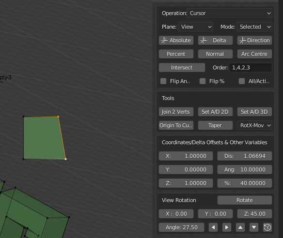
- Place cursor at 0,0,4 for example: Operation set to Cursor, X,Y & Z set to 0 0 & 4, Click Absolute
- Add Single Vertex in normal Blender way.
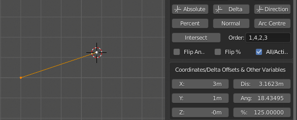
- Draw first Edge: Operation set to Extrude, Set Dis to 4, set Ang to -90, Click Direction
- Draw second Edge: Set Dis to 12 Ang to -30, Click Direction.
- Draw third Edge: Set X to 20 Y to 0 Z to 0, Click Delta.
A lot of dimensions are missing from that drawing… so it’s hard to tell exactly what is going on. But that should show some kind of workflow.
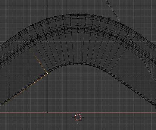
Now, there seems to be an area where you need to project a line of unknown length at -30 degrees on this profile, rather than what I did above. So for that you could do this:
Draw These Edges as before, length of sloped edge is not important.
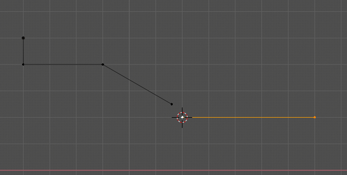
Draw This New Edge.
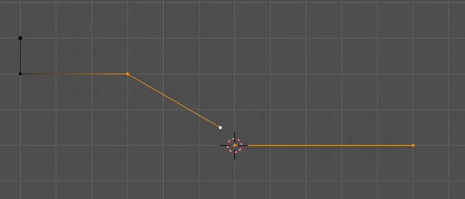
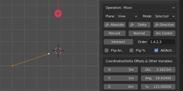
Select These vertices with your mouse, not a Box in order Horizontal Line vertices, followed by Sloped Line vertices. The order is not important provided the first two are one line and the second two are the other.
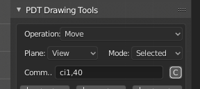
Operation is
Move,
All/Active is
checked, Click
Intersect.
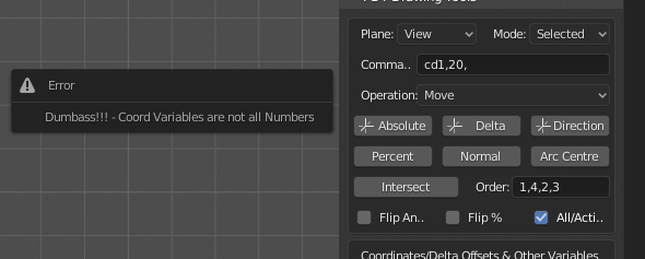
Some of the names of the buttons have changed since that version, but this should help you until I get the help file done. I need to do some more checking before I upload this version, I am not sure I have all the bugs out yet.
If you hover your mouse over the buttons, etc. I have provided some Tool-Tips that might be useful also.
The latest version has a new Plane set of Front, Top, Right and View, so you can now set odd view angles and work in the view plane, you will have to wait for this until the bug checking is done, hopefully not too long, maybe this weekend.
Thanks for the feedback, often you can look at something for ever and miss obvious points when you write the thing yourself. You grow with it I suppose, so feedback is very important.
Cheers, Clock.
 , I wonder why I never thought of doing this before:
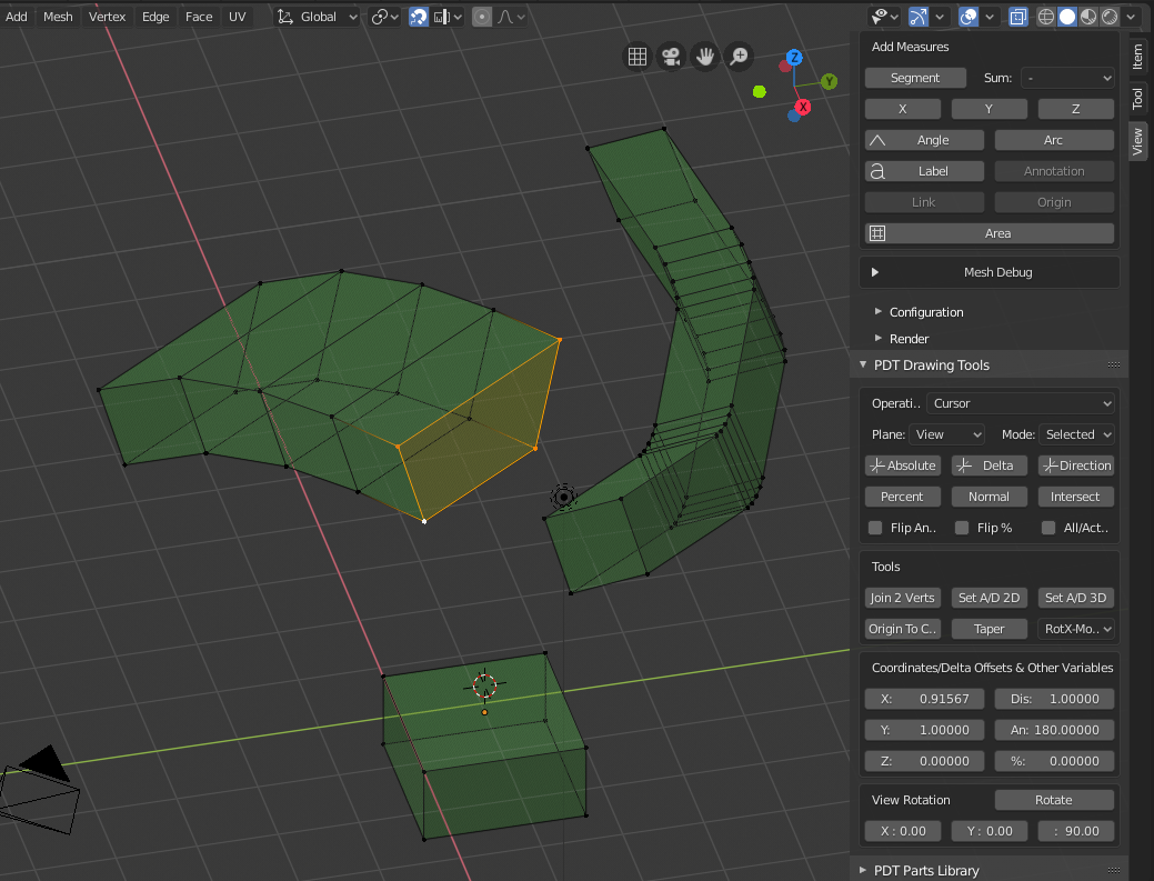
 . I also had to invert the view matrix in order to get the Intersection commands to work in view mode as opposed to standard XYZ plane modes.