Making an Add-on for Precision Drawing Tools (CAD)

Introduction

What started off as a request for help in making my initial work using Animation Nodes into an Add-on has grown significantly. After an enormous amount of work over four and a half months and an enormous amount of help here from so many people, we now have an Add-on that ships with Blender 2.82.

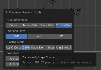
Precision Drawing Tools Explained

Artists tend to start with a primitive 3D form, then cut/extend/modify/etc. it into a final mesh. Dimensional accuracy is not necessarily the end goal of the artist.

PDT is aimed primarily at CAD Designers of all genres, to help them draw and model in a precise fashion.

CAD models are typically created by starting with a 2D plane (2D mesh) where faces (polygons) and sections are carefully drawn to dimensions and then extruded to produce a 3D model (3D mesh) with the least possible complexity and number of faces.

So unlike Artists, polygons and circular arcs are a Designer’s best friend, Sub-Division Modifiers are not!

Status

We know we still have work to do on documentation, especially looking at CAD workflow and modelling techniques, this is being addressed, but will take some time. We are also aware that there will be tuning and refinements to the system, these will be addressed as they arise.

We have plans to expand PDT to produce dimensioned Technical Drawings in the next major release, this is some time away still and requires more development from our initial experimental systems.

PDT Links

PDT GitHub Latest Release.
PDT GitHub Master Branch.
PDT GitHub Wiki.
PDT Issues.
PDT Blender Repository.
PDT On My Website.

Please try to use the Issues link above for any issues relating to PDT, that way they can be addressed in a professional, ordered & traceable manner.

Credit Where Credit Is Due

I should like to thank all those who have helped me, including Blender Developers and @BrendonMurphy who guided the process into the Blender repository and all those involved in the review process. I should also like to thank @ermo for joining the team and helping so much with getting my code up to expected standards.

Original Post:

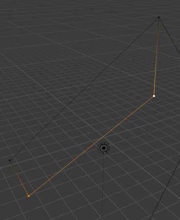
Hello, I have made the following CAD Functions node in AN (that being what I currently understand how to do):

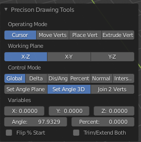
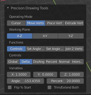
I would like to make this into an Add-on, titled something like “Precision Modelling Tools”, or similar. But I have no idea how to go about this. What I want is to have the various operator buttons and input boxes available in the 3D window when editing a mesh.

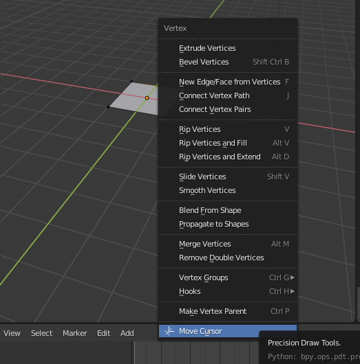
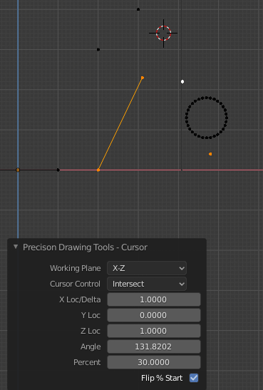
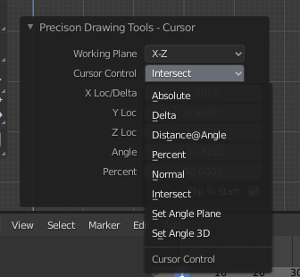
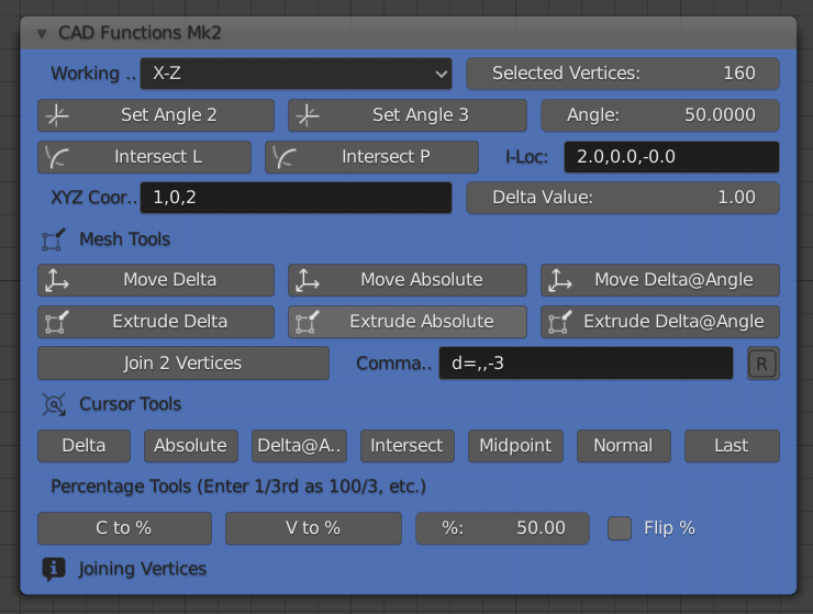
As far as the node is concerned, it does not require AN to be executing, has no inputs and no outputs. Examples of what it does would be “Place Cursor at a known XYZ”, “Move Cursor a delta amount from Selected Vertex”, Extrude a Vertex by a Distance at an Angle", “Place Cursor at Intersection of two Edges” etc. The user simply clicks the appropriate button to activate the command.

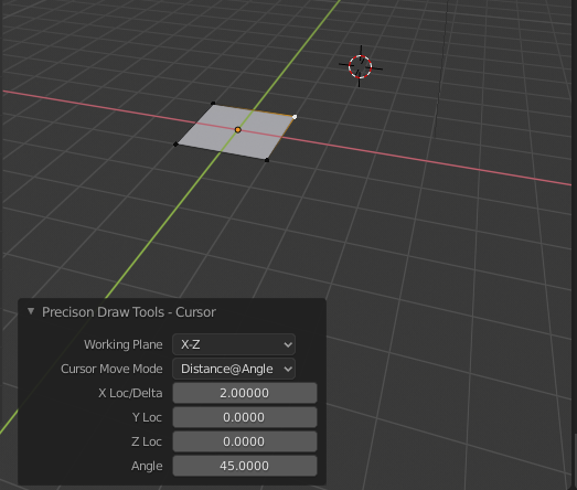
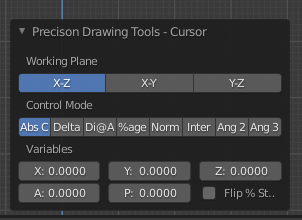
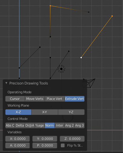
There are 4 input boxes, for Angle, XYZ Coord, Delta & Command (I=Loc is just for my information and is not used), but it would be nice if the XYZ, Delta and Command where just key-ins. So the user might select a vertex, key “e” to extrude, or click an “Extrude” button, then key, for example i=2,56 meaning extrude 2 units at 56 degrees in the chosen plane, this would be followed by more similar commands, like d=2,,4 (meaning delta values), so the vertex is extruded around a given “path” to form an edge loop, but not necessarily a face. If this is not possible, the command could be entered in the command box and is executed when Return is pressed. Angle needs to be stored as a variable as the system can measure angles between vertices and use them to move, or extrude, vertices.

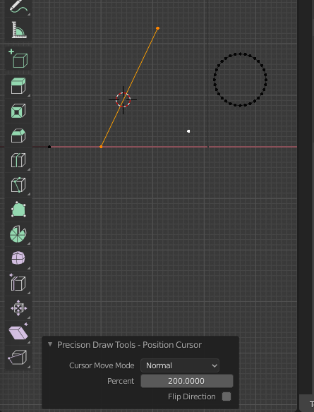
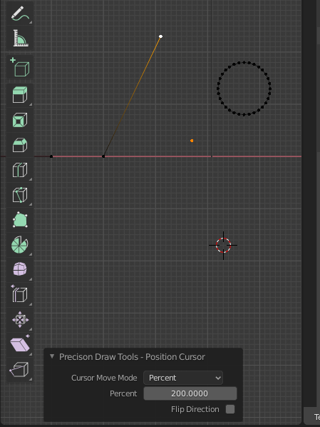
A further enhancement would be just to click a single “Cursor Move” button then key a=2,1,4 meaning absolute coordinates of 2,1,4 in XYZ, or d=2,,4, or i=2,78. Maybe the = sign can be omitted, so the key-in would just be something like a,,4 meaning XYZ = 0,0,4.

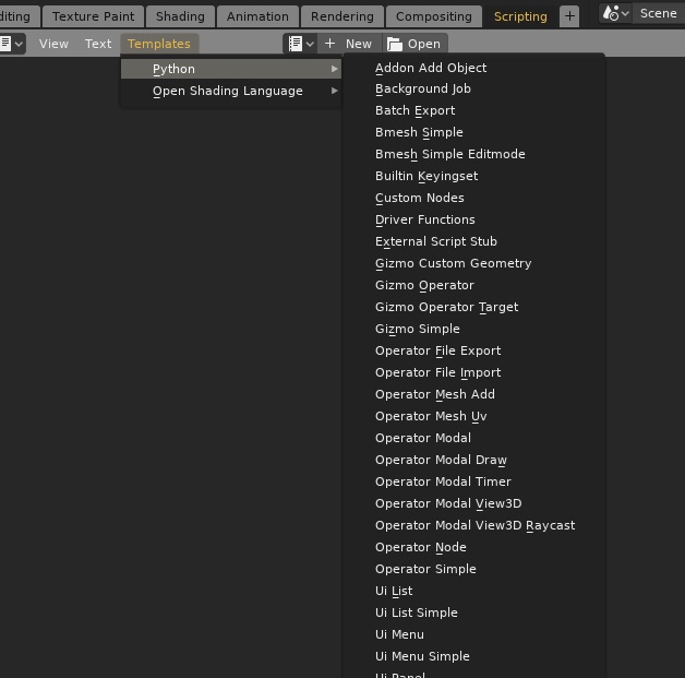
So, some questions; Is this possible in Blender 2.8, How would I go about it? How do I make an Add-on that users can easily load into Blender? I have written all the code necessary to drive the functions, much of which uses Numpy routines for speed and efficiency, particularly the intersect routines, I just don’t know how to make this a vanilla Blender Add-on.

These tools are intended to improve the precision modelling facilities in Blender and make it more “CAD-Friendly”, or that might be written as “Designer-Friendly”. Ultimately I should like to see these tools in vanilla Blender to attract Designers away from expensive CAD software.

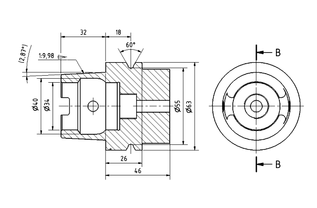
Here is a part made very quickly and accurately in Blender using the tools in my node:

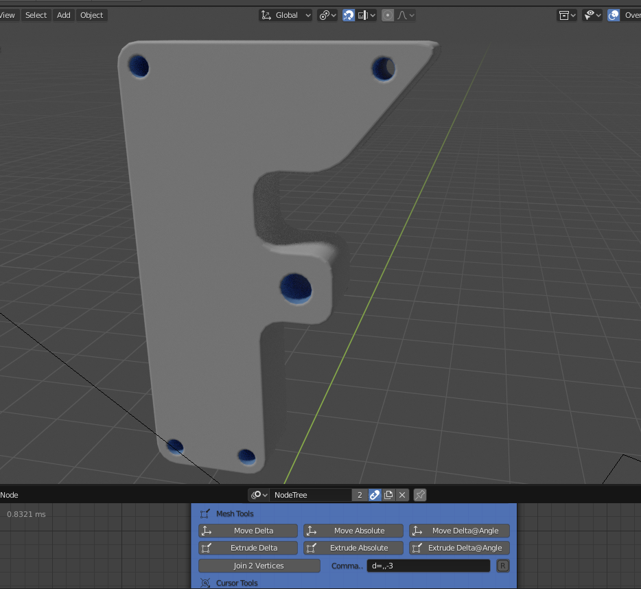
Thanks for any thoughts and help, Clock.

PS. I have renamed this thread now that I have found out how to do this…

17 Likes

Have to tried taking a look at the Blender API docs or the Addons Wiki page, yet?

3 Likes

You could look for an existing add-on that has a user interface similar to what you want, and look at how it is implemented.

2 Likes

Hmmm, so much to learn at my age, I will start reading… and looking for similar type add-on, maybe the offset_edges.py might be a good place to start? This is going to take me a long while I think.

Cheers, Clock.

PS. Thanks for the replies

1 Like

OK, I have made some progress, albeit a small effort so far:

Here is the “Cursor Move” option added to the Vertex Menu and below the menu to move it:

02

In this example I have set the cursor to be 2m @ 45 degrees from the selected vertex in the X-Z plane.

I need to work out how to call a common function that will be used for moving the cursor and moving vertices next.

Thanks for the help chaps, I am making good progress. I used the Add-Object Template to get me going, along with the offset_edges add-on.

Cheers, Clock. :cocktail:

4 Likes

Now, after a break watching TV and some quality time with Jack (Daniels), I have this working:

Cursor Normal, move the cursor to the normal intersection between the active vertex and the other two. An unexpected result was this one:

I selected two vertices and set the % to 200, to my surprise as I was expecting an error, it moved the cursor beyond the vertex, by the separation of the vertices, this will be useful to extend edges… Maybe I won’t put a max value of 100 on the percent input box after all… I really like Numpy!

Cheers, Clock. :cocktail:

4 Likes

Progress Report,

Having leant some new “stuff”, like how to call sub-routines, etc. I have come up with this:

Here the cursor has been moved to the intersection of the four selected vertices, below are the options for cursor placement that are now all working:

49

Now I need to work on moving vertices, then extruding them. What is really annoying is that there does not seem to be a method to move common functions, required in two classes, outside of the class definition. these means I either have to use the same class for all things, or repeat the common functions in the various classes, there would ideally be two, or three classes in the Add-on. But I am getting there, considering I did not know anything about making add-ons 4 days ago…

Cheers, Clock. :crazy_face::cocktail:

Is this better for a layout?

05

Cheers, Clock. :cocktail:

6 Likes

is much clearer …
if I could make a suggestion, instead of using mathematical names, would it not be more useful to use synonyms that describe the function?

for example absolute and delta, I have difficulty understanding what their use is

1 Like

Absolute means “Global XYZ coords”, Delta means “Location of Selected Vertex plus some X, some Y and some Z”. I will think of better ways to describe this.

Meantime all this is now working:

In this instance I have extruded the second-to-last selected vertex to the point where the active vertex is normal to the other two.

Now I have 2 questions I cant find answers to:

  1. How do you set the width of the dialogue box?
  2. How do you assign a hotkey to the dialogue box in the add-on .py script e.g. SHIFT+P opens the dialogue straight away?

Thanks for any help here!

Cheers, Clock.

EDIT:

Here is an example of the help…

57

2 Likes

now everything is clear…
the most immediate way is to use standard blender synonyms …
and also “type of workflow” if it is possible …
by doing so, blender users will find themselves almost immediately familiar with it.

have you already taken a look at the template scripts?
maybe there is something that could be useful to you

Looked in all of those - nothing there to help me… :frowning_face:

I looked in the Docs and found something, so I tried this:

class precision_draw_tools_cm(Operator):
    """Precision Drawing Tools"""
    bl_idname = "pdt.precision_draw_tools_cm"
    bl_label = "Precison Drawing Tools"
    bl_options = {'REGISTER', 'UNDO'}
#etc..

# Registration
addon_keymaps = []

def register():
    bpy.utils.register_class(precision_draw_tools_cm)
    bpy.types.VIEW3D_MT_edit_mesh_vertices.append(draw_menu)
    # handle the keymap
    wm = bpy.context.window_manager
    # Note that in background mode (no GUI available), keyconfigs are not available either,
    # so we have to check this to avoid nasty errors in background case.
    kc = wm.keyconfigs.addon
    if kc:
        km = wm.keyconfigs.addon.keymaps.new(name='Edit Mode', space_type='EMPTY')
        kmi = km.keymap_items.new(precision_draw_tools_cm.bl_idname, 'P', 'PRESS', ctrl=False, shift=True)
        addon_keymaps.append((km, kmi))

def unregister():
    # handle the keymap
    for km, kmi in addon_keymaps:
        km.keymap_items.remove(kmi)
    addon_keymaps.clear()
    bpy.utils.unregister_class(precision_draw_tools_cm)
    bpy.types.VIEW3D_MT_edit_mesh_vertices.remove(draw_menu)

if __name__ == "__main__":
    register()

Don’t know what I did wrong… Does anyone have any ideas?

Cheers, Clock.

That does look better! And I like that the buttons use the full width with that mode. But I think for “Control Mode” there are too many settings to have the options expanded. It’s cool to see your progress making all this more intuitive.

1 Like

Thanks! :grin: I agree, I would like to have these options on two lines (but I don’t think you can do that), or I will have to go back to “not expanded” I think, or I need to make the dialogue wider, but I cant find how to do that…

So here it is with the Controls not expanded:

29

Showing all options:

36

I think this is better than having all 8 across the dialogue? It still works as well for me as a user like this, but I am a bit biased. :rofl:

Cheers, Clock. :cocktail:

EDIT:

Having said that, is this even better - changing mode now only rrequires one click rather than two:

04

2 Likes

It didn’t quite work how I planned as there are two rows of options, so I had to put a “dead” option on the first row so the code used the second row, not sure I like this, maybe someone else could advise on layout, I am a bit out of my depth with add-ons… So this is how it looks now:

13

I will think on some more about what to do with it. I still cannot get the hotkey assigned, that bit is baffling me, does someone have a pointer for me here? I guess I must give up on setting the dialogue width, everything I try either does nothing or stops it working!

Cheers, Clock.

1 Like

hei @clockmender
I had an idea …
Do you think it would be too complex to add visual measurement tools?
In your opinion would it be feasible or would it be better if blender had a set of APIs that would allow this kind of functionality?
I reason about this because actually they should be neither lines nor objects that are part of a mesh but rather something like measurement and visual help tools.

1 Like

Do you mean dimension like on a proper technical drawing that can be printed? Like this:

36

If so I think it is a brilliant idea, I have used the measure tool in Blender 2.8, but it doesn’t work as I would like and is a bit “weird” in operation to a draughtsman. See below:

10

They also disappear when you select another tool. However, the basic building blocks of code must be there for someone to develop into perhaps a new type of object (a “Dimensions” object) that consists of lines and text and will print… On that subject it would be nice if we could print line drawings, without using grease pencil, has that ever been looked at? Edge loops not made into faces do not render AFAIK.

I had considered adding a set of measure tools to my CAD functions, so you could measure the length between two vertices and set this as the “Delta” distance for example. It is very useful to be able to look at an object and say, “How far apart are these points” and use that to extrude another point the same amount. Even taking two points that are not on the X-Z plane but use their length on the X-Z plane to extrude another vertex - I may have to make a picture to explain that! This is a very necessary feature, my routines already do this to measure apparent angles of edges sloped in all axes on a global plane, like X-Z.

This line at the back is not planar to X-Z, but its angle in the front view relative to the X axis was used to draw the highlighted edge, which is planar to X-Z, making a flat face:

03

It is definitely feasible to have these tools, using Numpy routines to measure lengths and angles is quite straightforward, very powerful and very efficient in terms of computing time.

What is the level of support within BF for these developments, it would be a bit disappointing to do a shed load of work only for it to be “lost”.

Cheers, Clock.

5 Likes

exactly.

but I’d like something more “pre-set”, that with a simple click would show you the size of an object or a segment, or an angle …
I know that perhaps I ask too much ^ ___ ^ and that perhaps they are instruments that should be expanded to the level of core developing @mano-wii

:+1:

1 Like

At the moment, I can select two vertices and measure their angles in all three global planes with one click of my mouse button, I see now reason why I cannot select two vertices and measure their apparent lengths on all three planes and their actual distance apart in space just the same.

From a CAD perspective, to dimension a drawing I would simply select two vertices, click the “Length Dimension” tool and it would add all the lines and text in one operation, or I can select two edges, click the “Angle Dimension” tool and it will add all the lines and text showing their separation angle. Putting dimensions on a model must be quick and easy, it can be so in Blender, but the tools available now are “not quite there yet” for a draughtsman. If there is support for this to be done, I will either do it, or help with it, but we would need to come up with an object that can take both Edges and Text.

Cheers, Clock.

1 Like