Making an Add-on for Precision Drawing Tools (CAD)

Hi Clock! yes I can do that (I like talking to myself - sometimes it’s the only way to get a decent answer :rofl:):

24

The node now measures the apparent length between the two vertices in any Global plane, or their separation in 3D space. The “Dis 2” and “Dis 3” Functions also fill in the X, Y & Z boxes with the X, Y & Z offsets between the Active vertex and the Other vertex. You can see here that the other vertex is offset 4 in X, 2 in Y and 3 in Z (making a 3-4-5 triangle in the front view) with a 3D length of 5.38516 (not shown in the dialogue as it is in Working Plane Mode). So you can measure with the dialogue to set the values for coords and distance as well as the angle.

I still cant get the “hotkey” to work… grrrrr!

Cheers, Clock. :cocktail:

EDIT: here is the 3D measurement shown:

45

1 Like

as I understand it, you’re developing a set of tools that help construct objects through precise parametric commands …
and this is a good thing …
but what about the reverse process?
construct objects through the drawing that have precise dimensions …

did you see the np station tool?
you could take a look at the code, maybe he can give you some ideas …
:slight_smile: :wink:

1 Like

Have u used the CAD tools before, cause I think that anyone who has used cad tools for even a day might be knowing what these are (i am NOT rude anyway, just pointing out that its not too un-intuitive at all, rather is a standard).

Okay, anyways, absolute mode means that the next point is with respect to world origins, and the delta, or incremental mode means that the next point is in relation/with respect to the previous point.

yes, often.

but my aim is to bring people coming from polygonal modeling to precision modeling.
therefore it is necessary to level up “the standard” with a simplification that makes life easy even for ordinary people.

Can I just say; Absolute and Delta, or Incremental, are terms that CAD operators are very familiar with, but we must not forget that we are trying to encourage CAD operators to switch to Blender, so must make that easy. We are also trying to switch Blender modellers to precision CAD techniques, so they can model more accurately and easily, so we must tread a cautious line here to satisfy both parties. I am all for educating polygon modellers to use CAD terms, but I see the need to make it easy for them to adjust, so these tools are universally accepted, to that end I do not mind if we find some common terms, or a way of using both sets of terms in maybe the “Tooltips”, etc.

Meanwhile, I have modded the Add-on so it also works in Object Mode, using objects to drive the functions rather than vertices:

Here I have placed the cursor at the point where the active object would be normal to the other two.

Certain things won’t work of course, like Extrude, or Place Vert, or Join 2 Verts - there is an example of me “stating the bleeding obvious”… However, there is one issue that I cannot resolve and that is to use the Intersect commands as I don’t know in what order the selection of the objects was made. For vertices there is a select_history, for Objects there is not. As far as I can tell even in 2.8 Official, you cannot tell the order in which objects where selected, So I blocked that option for now, but all the rest work fine.

I have also made it into a proper add-on stored in Blender addons directory and have solved the “Hotkey” issue, now SHIFT+P brings up the dialogue in both Edit and Object Modes - what a smartarse I am. :brain::rofl::joy:

Cheers, Clock. :cocktail:

EDIT:

Reading dimensions of a drawing used as a reference, now that would be good! You can enter them in the appropriate boxes by reading the drawing yourself, but that is probably not quite enough. I will investigate whether I can read dimensions from a DXF imported into Blender…

3 Likes

So, I just wanted to make a little challenge, if anyone is interested. Model the following please:

It doesn’t matter what the overall diameter is, or the length, I am just interested in the profile of the dimensioned bit, my overall diameter was 63mm, just to make it more awkward for me to make. Use only standard Blender and tell me how long it took. Permitted accuracy from mathematical true is 0.000001mm and no calculators are allowed. I would be very interested in how long it takes and how you would do it, so please let me know as much as possible of your process. I am a designer with CAD ingrained over many years, so it is interesting to see how a “Polygon Modeller” would approach this.

The reason for this strange request is that I am trying to optimally cover the Precision Modelling requirement for this type of construction and want to make sure I have got the function covered properly, so any help here would be gratefully received. If you would like to post the blend file, I can check the accuracy…

The dimensions were done with a very experimental method, although the text is not integrated yet, I still need an object that can hold edges and text.

Cheers, Clock. :crazy_face:

3 Likes

work starts to get serious here … heheh

if from what I understand, if @mano-wii will provide us with a set of visual helper measurement objects accessible via API, you addon devs will can have a lot of fun

1 Like

Certainly can! This will save me a shed load of work, but there is a proviso:

A Draughtsman need two inputs to add a dimension, the Point/Edges to be dimensioned and the direction and distance for the text done with a mouse click. They also need to set whether they are showing a global Axis dimension, or a dimension parallel to a slanted edge. I don’t think the measure tools cater for that yet?

Cheers, Clock.

It took my about 5 minutes, although I messed up the 4mm constraint and the right cutout ended up too deep.

It feels so silly but something the process of doing edge intersections is something I do a lot and the way I do it is by zooming in all the way and doing an edge slide until the center pixel of the vertex overlaps the line. I’m not sure if there’s a simple better way in Blender already, but I know this is being worked on as part of the snapping project and I can’t wait for it to make it in.

Another frustration I face a lot is the lack of measurement objects like you were saying. The existing measure tool only shows measurements when you’re in the active tool! I wish you luck in this project. I have to say though, one thing I’m worried about is the duplication of effort that can happen when this sort of essential work goes on in addons rather than master Blender. It’s so much harder to do it that way because projects seem to need a lot of momentum to get dev attention, but the ideal next step to me seems like CAD additions to master. This is something I’m passionate about too so hopefully I can help on this front soon.

1 Like

Thank you so much for replying. :grin:

Yes! been there, done that, but the accuracy is not 100% doing it this way and I got very frustrated at not being able to do it easily and quickly, :frowning_face: so some pictures:

35

Here I extrude the selected vertex 0.7 at 120 degrees using my PDT Extrude then I simply click PDT Intersect with the four vertices selected:

13

Trim/Extend Checkbox is selected, so the two nearest vertices to the intersect point are moved and de-duplicated forming a perfect 100% accurate intersect - in seconds. This is why I want these tools in Blender so we can ALL model accurately and quickly. Pressure here might work in time…

BTW, I have never found an accurate way to do this in Blender - only guessing when zoomed in a great deal, like you. But if anyone wants to prove me wrong, that would make me very happy. :joy:

As for adding measurements, I need this, you need this and so do many others and we want them to persist and print and be placed in accordance with good draughting techniques.

Cheers, Clock. :cocktail:

4 Likes

OK, question to the devs (suitable tugging of forelock):

Could we please have in Blender, soon:

  1. Ability to input a “delta” value when moving objects, or vertices, or extruding vertices, something like Select Object, key G D 0.1,0.3,0.4 to move an object 0.1 in X, 0.3 in Y and 0.4 in Z.
  2. Ability to input a Distance/Angle value when doing the same, something like Select Object, key G I 0,5,34 to move object 0.5 at 34 degrees in view plane.
  3. Ability to extend/trim two edges (or implied edge from two vertices) to their intersection, or place the cursor there.
  4. Ability to place cursor at the normal intersection between a vertex and an edge (or implied edge from two vertices), or move the active vertex to its normal intersection with an edge (or implied edge from two vertices)

Just four little things to make life so much easier for precision modellers. Please, pretty please! What are the chances of this?

Cheers, Clock. :cocktail:

PS I have done all the maths and logic to achieve this in Python.

I wouldn’t want to understand you need something totally different …
but currently you can set this through the modal operators …
select a vertex then press G then X then 0.3 then Enter for example …

to extrude:
select a vertex then E then X then 1.34 then Enter for example…

similar things for rotations …

edit:
I studied better …
yes it would be really nice what you ask :wink:

This feature already exists. Make a selection, hit G, enter a number, press tab, repeat.

1 Like

Done!

Bah, missed that part. Technically I “cheated” using Exact Edit, TinyCAD, and MeasureIt.

This might be too strict a tolerance for Blender. Blender is single precision floating point, which only gets you around 7 significant figures.
Representing 20 at a ±0.000001mm tolerance could require at least 8.

This took me about 40-50 minutes. It’s worth noting that a good chunk of that time was used up adding the dimensions with MeasureIt and because I had to start over from scratch partway through (I had to switch from 2.80 to 2.79 because Exact Edit was having issues with the former).

2 Likes

@ThatAsherGuy, I think you missed the point, I know about G X etc but this only does one axis at a time, so to move, or extrude in all three takes three commands. I am proposing we can do all three axes in one command. While I am on this, an absolute keyin would also be nice, so G A 1,3,5 would move, or extrude, to Global 1,3,5 - all three axes in one go.

I know these things can be done in Blender, but not efficiently, or in some cases not accurately and only very minor changes to the core code are needed.

@_nBurn good spot on the floating numbers, I guess I over cooked that trying to emphasise that having to fiddle intersections by eye when zoomed in was not good enough. What is amazing is that only one line of code is needed for “normal” intersection and only around ten for intersection two converging edges.

Thanks for the comments chaps!

Cheers, Clock.

As described here in the user manual, the feature you’re asking for already exists. It was implemented fifteen years ago. Press G to start the modal, type a number (without pressing X/Y/Z to specify an axis), press tab, repeat.

1 Like

Eeek! I stand corrected, Oh dear… I had better RTFM.

In which case can it be altered to be more in line with accepted standards, in that axes variables should be separated by commas, so 2,3,0.5 should mean 2 in X, 3 in Y and 0.5 in Z. And it should cater for Absolute (or Global) - relative to world centre, Delta - relative to some other point and Distance at Angle, relative to some other point in View Plane/Local Axes then? This would make it far more intuitive and far closer in line with other modelling software.

In the case of Delta, keying something like D 0.1,0.5 should move/extrude/etc. a delta amount in Global Axes and keying DD 0.1,0.5 should move/extrude/etc. in Local Axes. We must be able to perform these functions easily, consistently and intuitively.

E.g. Select Vertex, key E D 0.3,0.5 should mean extrude delta 0.3 in global X, 0 in Global Y and 0.5 in global Z (note I should not have to enter 0 if one value is 0 - so DD ,0.1 means 0.1 in local Z (I know you can also do G Z 0.5, but this keeps everything standard and uniform). This does not confuse the user with Tab switching from Edit to Object Mode for example. Does anyone else agree with me, if not I will shut up, maybe, if we can have inputs in “Absolute”, “Delta” and “Distance at Angle” modes.

Cheers, Clock.

Improved modal customization is on the to-do list, but there isn’t a firm plan for orientation switching without axis constraints.

Ok, but it would be nice to see this kind of approach one day…

By way of a quick test, I have just tried this:

So my mode is Extrude, my Command was d1.4,,1.1 so the active vertex was extruded 1.4 in X and 1.1 in Z. It’s a better, more intuitive workflow for a CAD trained designer, just saying. :grin:

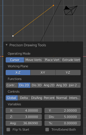
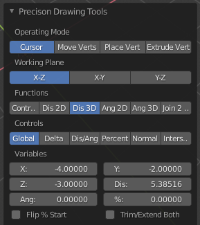
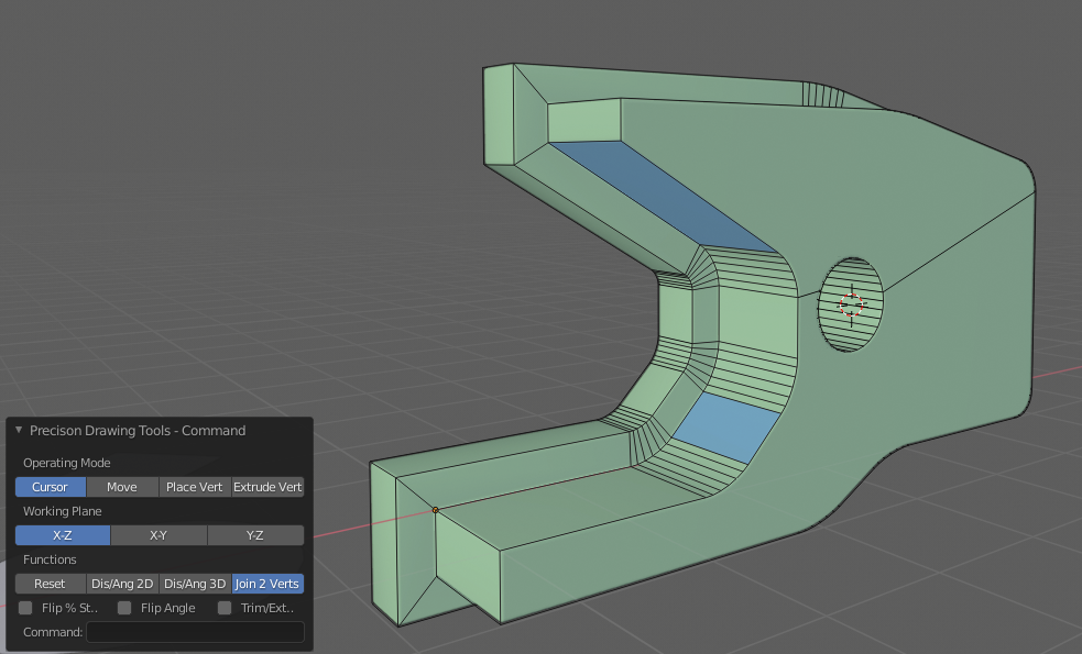
Well, I did some more work and came up with two interfaces now:

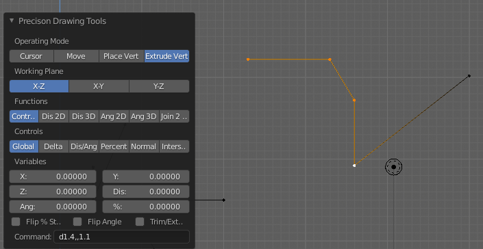
This one allows me to enter commands, such as a1,, in Cursor mode to put the cursor at Global 1,0,0, or v1,45 in Extrude mode to specify a delta of 1 at 45 degrees in the active plane. I can also enter i to get the intersection, as I did here to get the hole centred on the intersection of the front edge of the two blue faces. I can also enter commands like d1,3,2 for a delta offset from a chosen vertex, or n to get a normal intersection, or p30 to get 30% of the way between two selected vertices, from the active one.

If I enter something like vd,a it will use the distance and angle as measured by the Dis/Ang commands, a blank value will use 0, the Reset function zeros the stored values. An input like v1,a will cause the system to use the stored angle value, for example, similarly dx,y,z will use the stored X Y and Z coordinated as a delta. The point being that a blank will use 0, a number will use that number and anything else will use the appropriate stored value, so in fact df,f,0.5 would mean delta stored X, delta stored Y and 0.4 in Z.

One issue I had was that I did try to display these stored values in the dialogue, or in the message area, but they did not update when I clicked the options, only on the second time I clicked them, I guess there must be an update option in the variables, but I have not found out how to do that yet.

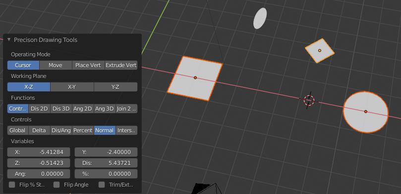
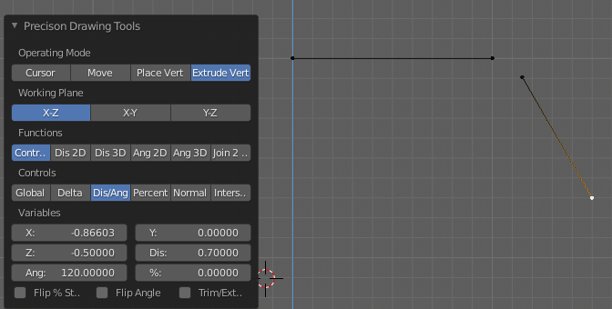
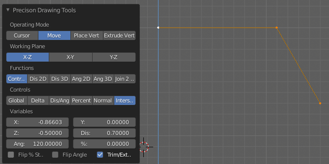
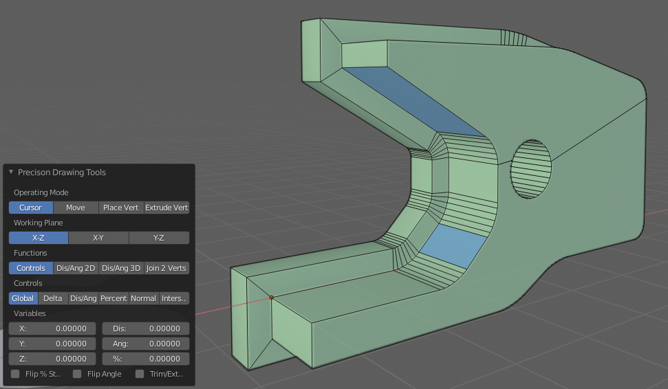
I can also use the other interface that allows me to use options rather than keyed commands:

So now I need to know how to make this a patch for Blender, so these commands could be used for normal modal inputs, like when you key e to extrude a vertex. I might see if this is possible…

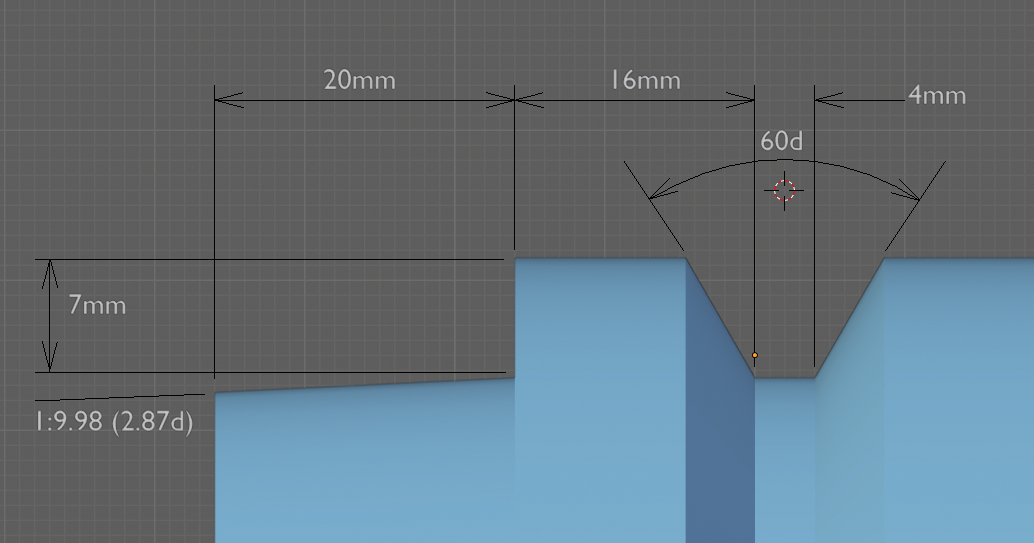
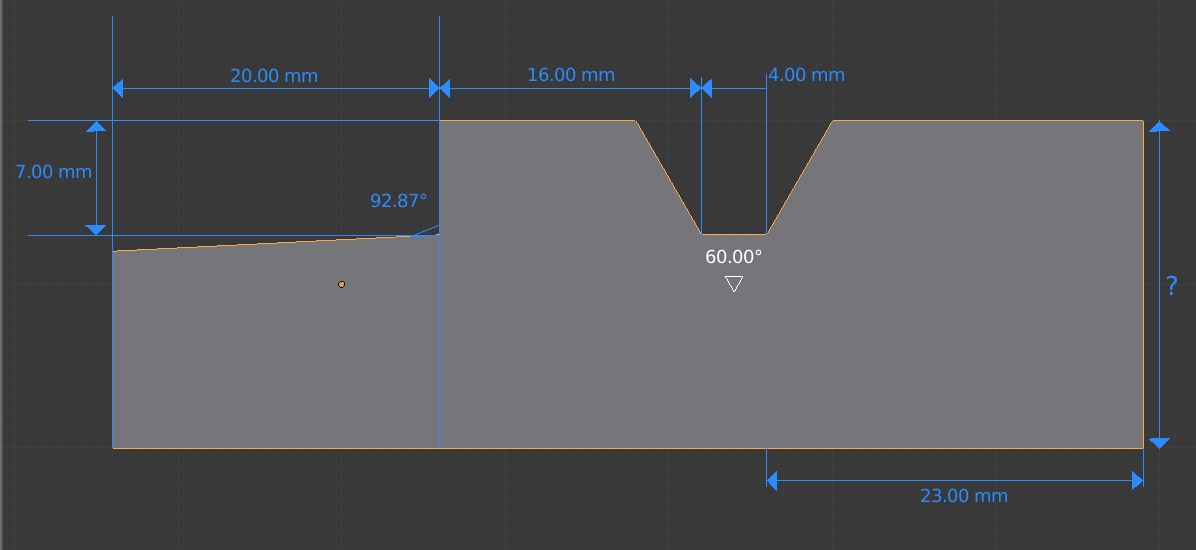
The part was made using my Add-on, Offset Edges Add-on and standard Blender routines.

Cheers, Clock.

1 Like