Loops are one of the most requested features for geometry nodes. They allow executing the same nodes an dynamic number of times. This proposal shows how loops could work in geometry nodes.
The first observation is that there are actually two kinds of loops that are of interest for us:
- A serial loop allows executing a node multiple times whereby an iteration can take the result of the previous iteration as input. This is essentially the same as creating a chain of nodes that contains the same node multiple times.
- A parallel loop also allows executing a node multiple times. However, this time the output of one node is not passed into the next node. Instead, all nodes can be executed at the same time and all results are joined in the end.
The sections below describe how both types of loops could look like in geometry nodes. Since the serial loop is more generic, the corresponding node is just called Loop in this proposal. The parallel loop is a bit more specialized, and since we are in geometry nodes, we generally want to do something in parallel for various geometry elements. Therefore, the corresponding node is called Geometry Loop. We might have a more generic Parallel Loop node in the future, but that is not really required right now and would make common use cases harder to achieve. Therefore this proposal focusses on a solution for geometry processing.
Loop
A design for a serial loop has to provide an answer to how the user specifies the following things:
- How many iterations are run?
- Which inputs are used by the first iteration?
- Which data is output by the last iteratiton?
- Which data is feed back into the next iteration?
- Which nodes run in each iteration?
- Optional: How to access the current iteration index?
- This is optional, because one could just manually increase an index by one on every iteration.
Since a serial loop is very generic it should not be required to have any geometry to use it. This would theoretically also allow us to use the same loop construct in other node systems in the future.
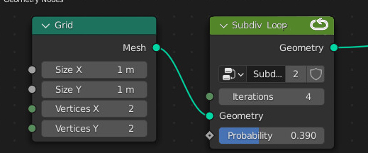
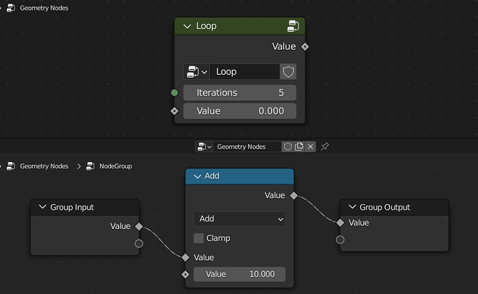
This proposal solves this by introducing a new Loop node. This node is similar to a Group node, but instead of executing the referenced node group only once, it can run the node group a dynamic number of times. To create a new loop, one just has to add a Loop like any other node. It will look something like so:
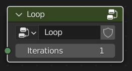
It has a reference to a node group and an Iterations input. By default it might reference no node group. Instead a default node group would be created when first hitting tab to enter the group. On the inside there is just an empty Group Input and Group Output node by default. We could also have Ctrl+G like behavior to create a loop, but that could be added later.
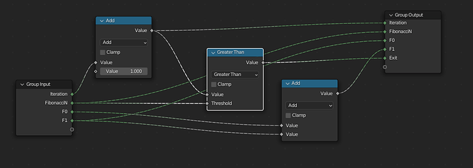
One of the simplest (and least useful) loops one could build is one that just adds ten to a value in every iteration. In this setup the output of the Loop node would be 50.
Here we also see an interesting thing, the Loop node knows that that the output should be passed back into the group in the next iteration. In the current design this mapping between input and output sockets is just based on the name. We could think about some more explicit mapping, but currently I think just using the name is good enough, the most straight forward and easy to understand. The handling of name collisions needs some consideration, but a simple solution would be to just show a warning in that case and to not execute the loop until the problem is resolved.
We can also note that the initial inputs to the node group are provided from the outside.
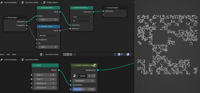
Below is a more interesting example that actually modifies a geometry multiple times. This example also shows that there can be an input that does not have a corresponding output socket. In this case the same value is passed into the loop in every iteration.
The opposite is possible as well. There are can be an output that does not have a corresponding input. In this case, this output is only computed in the last iteration. When the number of iterations is zero outputs that correspond to inputs will just be passed through (same as when the Loop node is muted). Other outputs will get a default value, which is usually zero or an empty geometry.
A new Iteration node can provide easy access to the index of the current iteration. This node can only be used in Loops. Note that it does output a single value and not a field like the normal Index node.
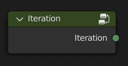
Generally, the number of iterations in this kind of loop should be relatively low. This is to avoid unnecessary slow computions, because the individual iterations cannot be executed in parallel.
Geometry Loop
The new Geometry Loop node allows creating a loop where all iterations can run in parallel. This allows for much higher iteration counts in practice.
A design for a parallel loop has similar but slightly different requirements compared to the serial loop design. It has to answer the following questions.
- How many iterations are run?
- What data is passed into each iteration?
- What data comes out of each iteration?
- How are the outputs from each iteration reduced/joined to get values that can be further processed after the loop?
- Which nodes run in each iteration?
Similar to the Loop node, the Geometry Loop node can just be added through the Add menu. It also references a node group that one can tab into. Instead of an Iterations input, it has two inputs by default: Geometry and Selection. It also has a Geometry output that outputs nothing by default (this is technically optional, but the node does not make sense without a geometry output).
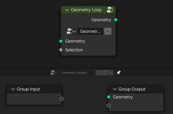
Additionally, the node has a dropdown menu to choose a mode from (this is missing in the mockups). In the menu one can choose a domain (e.g. points, edges, …) but possibly also other modes like instance references, which would run the node once for every different instance.
The number of elements in the geometry, the mode and the selection together determine how often the referenced node group will be executed.
Like the Loop node, the Geometry Loop node also needs additional nodes to flourish. The naming is of course still up to debate.
- An Element Geometry node that gives access to the geometry that corresponds to the current execution(e.g. a single point or face).
- In theory we could also retrieve this from the Group Input node, but that would result in having different behavior for different inputs which I’d like to avoid.
- Depending on the selected mode, this will output a different kind of geometry
- An Evaluate at Element node that evaluates a provided field in the geometry context of the current element (e.g. the current point or face).
- It would also have a data type dropdown menu.
- Note how it has a field as input but outputs a single value.

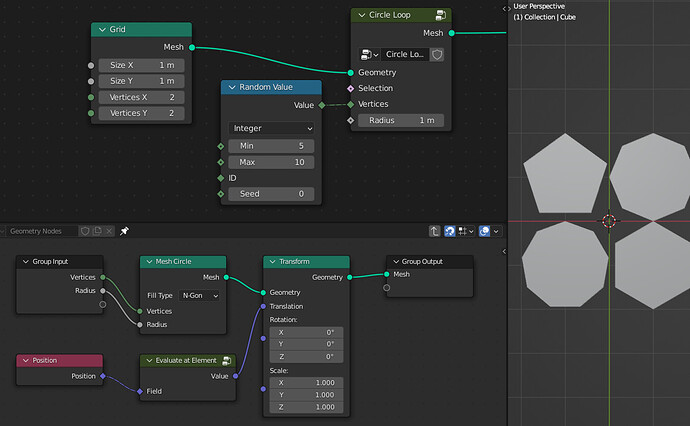
The image below shows a slightly more complex example. It creates a circle mesh on every point of a grid. Whereby the number of vertices in each circle is randomized.
Let’s look at a couple of different aspects of how the Geometry Loop node works based on this example.
- The node group in the loop outputs a different mesh for every element.
- The geometry outputs from each element are joined into the final mesh output.
- Even though the Vertices and Radius input do not support fields inside of the node group, they do support fields on the outside.
- The Geometry Loop node evaluates these fields and passes single values into the node group for each element.
- If the node group has an input that supports a field, that will also be exposed as a field on the outside. In this case the field will not be evaluated automatically. It will just be passed into the node group without changes.
- The combination of the Position and Evaluate at Element node give access to the position of each grid vertex in the loop.
- The same could be achieved by exposing the Translation from the Transform node as an input and passing the Position in from the outside.
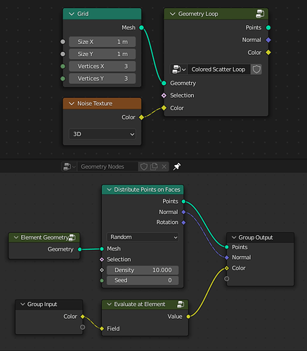
The following image shows an example that points on each face individually. All points on the same face will get the same color. Note that this is not the most efficient way to achieve that (instead one could use an Attribute Capture node to capture the color on the face domain before scattering points).
The example shows a couple more aspects of the Geometry Loop node:
- Not only the output geometries from each element are joined, but also the output fields.
- All output fields are captured on the individual output geometries and then they are joined.
- The domain where the attribute is captured is determined by the Attribute Domain set for the group outputs that already exists for the modifier panel.
- Even though the node group outputs a single color for each element, the final output of the Geometry Loop node is a color field. This field references an anonymous attribute on the Points geometry.
- The Element Geometry node outputs a mesh that contains a single face.
Some more misc aspects that I don’t have specific examples for yet:
- The selection input to the Geometry Loop node allows only running the loop for all the selected elements.
- The node group can output multiple geometries.
- This will result in multiple Geometry outputs in the Geometry Loop node.
- All output fields will be captured on all output geometries. In the future we can do some better static analysis of the node tree to determine which fields do not have to be captured for which geometries.
Conclusion
Both of these nodes make geometry nodes significantly more powerful. Sadly, I didn’t got to creating a prototype yet. Depending on the feedback, we will either update the proposal, create a prototype are start with the real implementation directly. The initial focus will probably be on the Geometry Loop node, because that solves more common use-cases.
When providing feedback, I recommend you try to create mockups for node trees you’d like to build. All of the mockups in this proposal have been made with Blender node groups without changing the source code.
FAQ
This section contains my current answers to frequently asked questions.
Can we put loops into the top-level node tree to avoid the need for node groups?
Yes, I think I’d prefer that as well, but there are some caveats.
- To make this work, we need some new kind of frame node that contains the entire loop. Without that we’d get:
- Even more different execution contexts in the same node tree.
- Even more rules for what kind of links are valid (e.g. you couldn’t just link from the inside of the loop to stuff that’s outside).
- Possibly ambiguous behavior with nested loops.
- Something similar to “old-style” node groups could work (see screenshots here).
- Implementing loops this way will be signifantly more complex.
- This is not really an argument against having loops directly in the top-level node tree, but it may impact how we get there.
- Loops as node groups I could see ready for Blender 3.1. Loops that require very new ui functionality not so much, but would have to look into it more.
- Versioning code for converting one kind of loop to another should be relatively simple.
- If we use this approach, it should be used for both kinds of loops.
More mockups in that area are welcome, but they should take the following notes into account:
- There should be some kind of frame around all the nodes inside the loop.
- The general ui solution shown in the mockup should be applicable to both kinds of loops.
- The original proposal contains some questions that a loop design should answer. Make sure the mockup or additional text answers these questions.
Can we have an Entry/Break node in the loop?
Yes. I actually intended to mention that in the original proposal, but forgot about it. We can have both nodes.
If the loop contains an Entry/Break node, can the iterations input be removed?
In theory yes, in practice no. Removing the iterations input would make it very easy to accidentally create infinite loops. Even worse, since that would make the entire system turing complete, there is no general way to detect if there is an infinite loop (see halting problem). Always having a max number of iterations solves that. The user can of course choose to set the number of iterations to a very high number, but that would be a very explicit choice.
Why not extend the concept of fields to “Geometry Fields”?
In the past we thought about and discussed expanding the field concept to include geometries. It’s certainly possible and it would provide a bit more flexibility, but that flexibility does not come for free:
- It adds even more (nested) evaluation contexts to a node group (similar to top-level loops without a “frame”). The current fields did that as well, but provided significant usability improvements for common use cases. Geometry fields would provide significantly less to no usability improvements.
- Already existing tooling for the current field system would become worse, because the distinction between sockets that support fields and those that don’t goes away. That makes it much harder to produce useful and correct warnings.
- The same flexibility could theoretically be added later. We could investigate if we can somehow pass node groups around that are invoked somewhere else. I have some ideas for how that can work, but have to put more thought into it. Right now it’s not important enough.
Can sequential loop and normal groups be combined?
I think think building a group as an asset and building a loop are two fairly distinct things. Combining them does not help imo and may make things more confusing. Also, changing how the Group node works may be problematic, because we want to use the same groups in different node tree types, and it’s not likely that all node tree types will support loops. This would also make it harder to convert node-group-style loops into groupless-style loops if we ever wanted to do that.
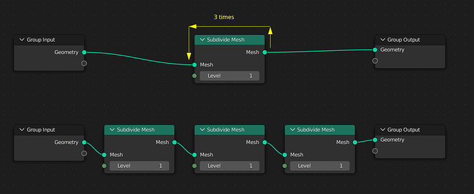

 .
. (not really serious, it’s difficult to find a good name for it).
