first time testing this branch.
this is a really cool development, i can imagine this in a few version combined with modifier nodes masking and combining different bevels, this is going to be a really good tool to have ![]()
![]()
![]()
first time testing this branch.
this is a really cool development, i can imagine this in a few version combined with modifier nodes masking and combining different bevels, this is going to be a really good tool to have ![]()
![]()
![]()
just played with the build a bit - good progress, curious how you end up treating the orientation and vertex mesh problems.
Just wondering if there would be an option to make the profile symetrical - would that help in creating a cleaner vertex mesh?
another thing I noticed and wanted to ask if that is planned - assume you have a 3x3 plane, and put the center quad into a vertex group. Now if you add a bevel modifier to that with said vertex group - the profile does nothing as the bevel shape is flat. Would’t it make sense to introduce some ‘depth’ or ‘scale’ value to push things in/out? That would allow for some very cheap panel like effects 
Yes I also wanted to ask if you could make an option for a symmetrical profile. So the user would only need to draw one side and it would get mirrored. I think that symmetrical bevels are a common use case. But it is hard to place the points so exactly.
What about horizontally flipping the profile editor?
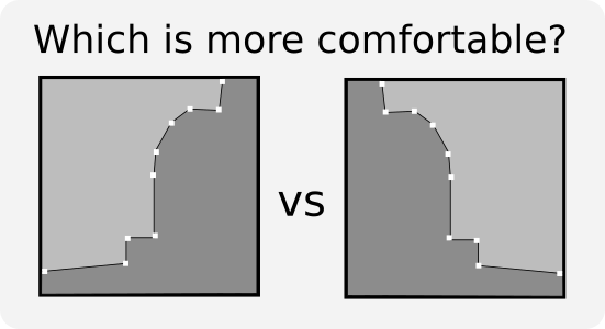
It’s currently the left one, but for some reason I prefer the right ![]()
I like the right also. I’ve worked for a lot of architects matching their trim selections, and the manufacturers usually draw trim profiles this way. The flat side is almost always on the left or bottom of the illustration.
I agree. Grid method and Boolean are both useful.
I don’t see Islands as a problem. Remesh modifier is able to ignore Isolated parts.
There could be ability to keep only main island.
It is obvious that Triangulated fill gives an ugly result. But why did not you try a method with N-gons ?
This is a great idea! I actually think by the end of the summer I’d like to finish both the “grid fill” option and this method. It’s not quite as good as the boolean method but it shouldn’t take nearly as long to code.
There’s still amount of stuff left to add, and I don’t want to spend the rest of the summer implementing another VMesh type and leave more important things unfinished.
I’ve been considering this for a while but I hadn’t reached a point where it would be useful. I guess it would enable yet another vertex mesh method where the lines would continue and meet in the middle. So I’m not sure I’m going to prioritize it but I’ll keep this in mind. Although if I ended up making the boolean method I don’t think this would
You have a good point that I could also just add a symmetrical feature to the profile widget for drawing-- it doesn’t have to come with a vertex mesh method too. That’s much more doable.
The triangulated fill is just a triangulated Ngon. So they’re actually the same, although I didn’t use smooth shading.
There seems to be a fair amount of support for this, so sure! I did it the other way because that’s how the curve widget works, but profiles are different! And I want to build this with common use cases in mind (as much as possible).
@HooglyBoogly @CandleComet @Howard_Trickey
Rotate, flip, invert with an all (all points selected) and selected (selected points only) options for the bevel profile would be useful.
Bevel
Bevel profile: [ Curve ]
Profile orientation:
Rotate: [ All ] [ Selected ] [ 45° ]
Invert : [ All ] [ Selected ]
Flip : [ All ] [ Selected ] [ Horizontal ] [ Vertical ]
[ User Input ] [ Toggle ]
I was thinking about a result like that
or like that
That is not just a question of smoothing. A triangle vertex should not goes at location of vertex at minimum value of profile.
It should stay on edge of intersection, clamped by distance of vertex of minimal height.
At that condition, Ngon or a triangulated Fill can stay planar and have an acceptable smoothing.
Anyways, I just realized I missed CandleComet post. He got the point. His cut-off method is satisfying.
Just out of curiosity, what happens at a four-way intersection ? Does one edge loop take precedence or are you going for an extension of the three-way intersection solution ? (ie cutoff in the middle)
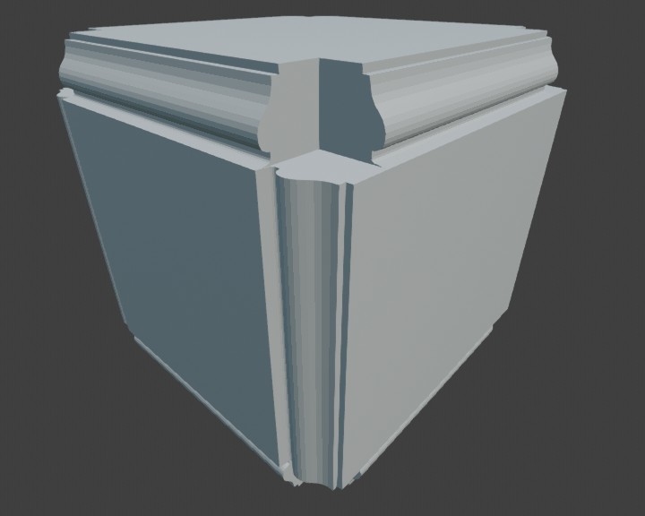
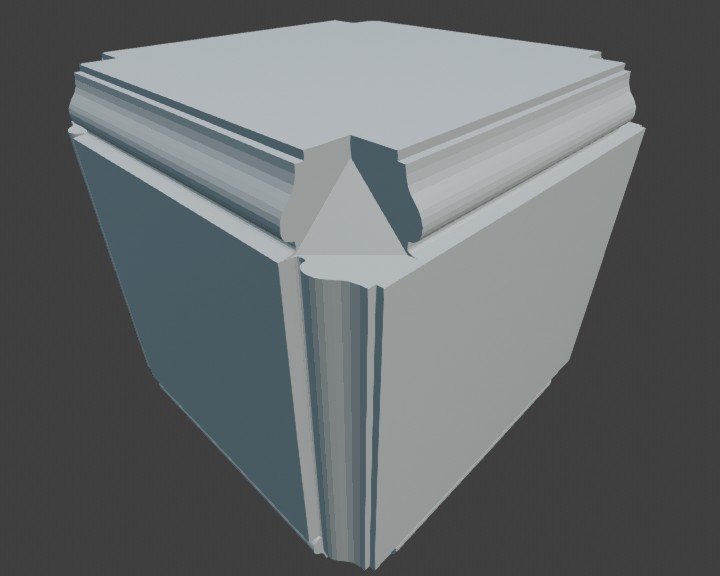
What about an n-way intersection ? Actually, does that question make sense at all… ? I feel like these profiles are meant to be used mostly on contiguous edge selections anyway ? As on this thing :
I haven’t seen a use case for these n-way intersections either! Someone suggested not even allowing them to me earlier, but I think it has to be an option, regardless of how perfect the solution is. People have strong imaginations, why limit them?
Any intersection with 3 or more inputs should have the same general solution. My goal is to implement the grid fill method and the cutoff method that @CandleComet described.
EDIT: Also, I can’t wait to see someone make something like that with this tool, it will be really cool to see what people do. Yesterday I fixed the bug with saving and loading Blend files with the bevel modifier, so it’s more possible now.
When I look at where 2-edge and 3-edge bevel intersections crop up in my own modeling, I don’t really have a use case for 3-edge bevels with asymmetric profiles. Would the averaged profile ring solution be more viable if it only had to handle symmetric profiles?
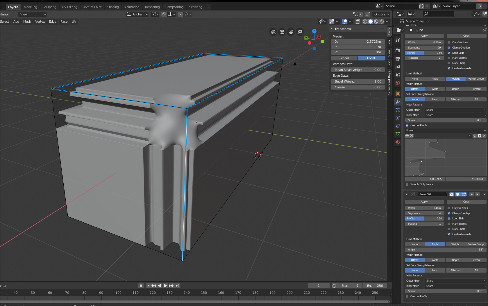
The averaged profile ring method would definitely be more viable with symmetrical profiles. In my picture you can see how well it worked for the normal looking profile in the middle. And maybe that’s something I can add at some point, but I think a higher priority vertex mesh method for the symmetrical case would be something that looks more like the boolean method.
Another question I (one of the mentors on this project) have been discussing with the student is: how to sample the profile if the user specifies an “number of segments” that is different from the number of segments implicit in the points drawn in the profile widget?
For the non-custom bevel, the code tries to make equal-width segments spanning the superellipse arc.
For custom bevels, this is unlikely to be what the user wants unless all the points on the profile are smooth and the number of segments is high enough that equal width segments gives a good approximation to the original profile. Otherwise, the user probably wants the points they explicitly drew in the profile widget to be points on the beveled edge profile.
Let’s call the profile that the user drew “the input profile” and the profile that the modifier will use to make the beveled edges with the specified number of segments “the output profile”.
Some likely requirements:
What do people think? Does this sound about right? For the places about where I have questions, what do you think the right answer is?
Of course, an easy answer would be “give the user options to choose whenever there is a choice”. I think we would prefer to avoid a proliferation of options, if possible – that is, if a particular set of choices gives most users what they would prefer most of the time.
It seems hard to imagine use cases for an assymetrical profile on a 3(or more)-way intersection. Two of the edges would be aligned with each other, but not with the third one, which is strange. It makes more sense to use such profiles on continuous edge loops.
But with symmetrical profiles I can imagine wanting to use them on many edges at once, which would include 3-way intersections. Think woodworking, mitering all edges. In this case the best solution for me would be your Boolean solution.
I would think the user would expect all of the points that they specified represented in the end result. Sharp points and smooth points should all be there. The segments setting should just adjust the number of loops created between these points. You may be able to optimize it where a sharp point adjacent to another sharp point would not insert loops, but in most cases I would think all of the points you put in your profile should be there.
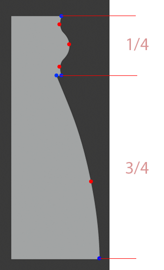
It seems like your other suggestion of dividing it into sections would be nice, but it could result in unpredictable results as well. I’m mostly thinking of how the smoothing will be set and represented on the screen. For some trim that isn’t a major focus of the scene, I may want to use a small # of segments. Now, if you look at trim profiles for interiors and furniture, they often have a lot of small curvy features at the one end and maybe one long curve at the another. If you base this completely on distance, you will end up all of the detail added only to the most gentle curve. So if the curvy detail takes up 1/4 of the total length of this profile, and then you set to 4 segments, then there will be no segments added to the most detailed part. So are these points detailed parts going to be smooth shaded? Autosmooth often won’t work in these situations, because you may have parts that need to be smooth shaded that have an angle close to 90 degrees, but if you set your autosmooth angle that high, your sharp corners will be smoothed as well.
That was a lot of talk just to say that that segments need to based on Curvature, or simply be a number of subdivisions between points, but that’s my (long-winded) opinion.
Thanks for the response and diagram. It does illustrate why this isn’t an easy problem. Basing the number of points on curvature was one of the options I mentioned above, and you made a good case for that. As well as a good case for not distinguishing between sharp and smooth points as some of my options did.
Do we think there’s a use case for sampling fewer points than the user inputs? If there isn’t then that simplifies some of the logic quite a bit. If we ignored the segment input if it was smaller than the number of input points, then the problem becomes “How to distribute the sampling of extra points” which I think is a simpler problem.
The simplification this enables is ignoring non-curved lines between vector-handle points. So the extra points can be sampled only on the curved edges. The only problem is if all the points have vector handles, increasing the segment count beyond the number of user points wouldn’t do anything. Even though this is a bit confusing, I think it’s ok-- at that point you’re just adding redundant information.
I think another key piece of information is that in general, to have more curvature, points need to be closer together. So sampling the extra points evenly for each curved edge will put points closer together on more curved sections of the profile. And the remainder of points after this even distribution can be assigned to the most curved edges.
By the way, I hope to use the same code for creating the table of points that the profile widget fill is drawn with. In that case the number of segments to sample to would probably be something like 256. The cap for user defined points will need to be smaller than this.
@HooglyBoogly @Hadriscus @Howard_Trickey @RonanDucluzeau
Selected vertices/edge: bevel interpolation
The selected vertices/edges order of interpolation could be done using the following (user selected) options;