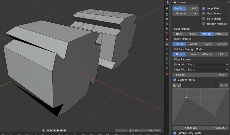
That’s the plan for the “Sample only points” option. When it’s on it will use exactly the points you place down, but when it’s off it will evenly space the points out along the path “with curves” defined by the points.
The CurveMapping widget already had the ability to use bezier curves, but it was just for an X-Y mapping, so I have to rebuild the functionality for the new ProfileWidget. I’ve been looking into this for a while, but I haven’t made a push on it yet. Maybe this week.
One thing I’m not sure I understand : unlike the CurveMapping widget, with which there can be no overhangs - or as you more accurately put it, every Y value is a function of X - how do you determine the connection order of points in your new ProfileWidget?
Interesting question, and it’s a good time to ask it because I just implemented a new insertion algorithm that checks which index to place a new point at. The only time you really define the order is when you add a new point.
I first tried finding the closest point to the new location and putting it either before or after that point depending on which of its neighbors was closer. That didn’t work very well! I settled on something simpler: It places the new point between two consecutive points whose line segment is closest to the new location. Does that make sense?
I think I understand. I’ll have to test it out though ! I didn’t even have time to try the branch so far.
In any case, altering the order of points is not possible after insertion if I understand correctly. (I don’t see how that would be possible anyway…)
One last thought on your reply to @Zsolt_St : in the case where the user draws a bézier curve, they might draw a sharp corner where they want a point to fall on - however if the sampled points are evenly spaced no point might fall exactly on it, and the profile shape would be biased unless a high number of segments are added - would it be reasonable to have a point for every curve point, in addition to the sampled ones ? (ie subdivide the bézier curve parametrically)
If it’s useful for people, it would definitely be possible to add buttons to move the point’s backward or forward, but I think doing it automatically would be a little annoying. But you can just delete it and create a new one, so I don’t think this is a high priority.
I’ve already run into this problem with the equally spaced points! It seems like there could be some complicated solutions to this problem. I do think the solution will have to be more complex than add the profile points in addition to the sampled points.
I do like the idea of subdividing the curve like you say, so the only extra points would go in between the curved edges, not the clamped ones. Hopefully I could re-use some code here between creating the high-res curve for the ProfileWidget’s display and the sampling of the bevel segment’s locations. The only thing I worry about is that the current bevel code tries to space the profile verts out evenly. If they aren’t I worry it will make solving the vertex mesh problem harder.
Each point in the curve can be selected and individually assigned to a corresponding vertex on the mesh by the user. And, vice versa. (Each point mask/ID can be changed by the user.) Think masks/IDs/cryptomatte and vertex snapping.
Control vertex distribution: weight paint (a curve):
Preassign a vertex weight paint layer to the curve. The vertices of the mesh are distributed according to the vertex weight paint (curve).
The vertex to curve (point) would act as a threshold for the vertex weight paint, creating custom vertex distribution groups (ranges). Think color ramp and IDs/colors (cryptomatte).
By default the vertex weight paint would have an equal distribution. An on/off toggle can be used to change the default equal distribution (Off) to a custom distribution (On).
Currently, it looks like custom profiles is not working if it is applied on a unique edge.
It works with a succession of edges. But for one edge, profile is fine at one vertex of edge and inverted for the other one.
You probably noticed that.
But I am wondering : did you plan to add an editable orientation for bevel edges marked in Edit mode ?
Currently, Bevel Weight works as is from0 to 1, below 0.5 => no bevel, above 0.5 => bevel.
It could be from -1 to 1, 0 => no bevel , above 0 => bevel in one direction, below 0 => bevel in the opposite direction.
In screen capture, result of front face from first cube is as legitimate as result from cube without error.
I’m not quite sure what you’re describing here, or if we’re using the same terminology. Are you talking about a way to distribute sampled points across the curve? I"m not sure it’s necessary to expose that to a user. If they want to position points precisely I would think they could just use the Sample Only Points mode.
I just found that bug yesterday too! It looks like the profile orientation regularization pass doesn’t properly travel in both directions if it hits an impassable vertex first. This happens within a single edge on a cube too because it doesn’t travel beyond the cube corner (no best choice of which way to go). I’ll look into this soon.
First of all, there’s no obvious way to turn the bevel weight into an absolute orientation, it could only be used as an “invert whichever orientation was chosen by default.” Also, if the bevel weight were used for this it couldn’t be used for the offset width!
That leaves a couple options:
Add a new edge tag used for just this, “Bevel Profile Orientation” or something.
Add a “reverse” button to the profile widget and require the user to do multiple bevels to get different orientations.
Right now I’m leaning toward the second option, especially in the short term.
I’m thinking of a couple heuristics that could be used to determine a common orientation for a set of continuous edge loops -
for n edge loops being beveled we could isolate the first n end vertices that are closest together - that would work for long edge loops such as pipes etc. but wouldn’t work for short edge loops
For other/mixed cases it gets more complex. Maybe use two methods, one for main detection and one for fallback ? or use vertex number ? but then user control over this is quite limited so…
By default the vertex distribution is equally distributed along the bevel profile (a curve) using a vertex weight paint layer. (Toggled: Off)
Unless the user selects custom distribution. (Toggled: On)
Custom distribution:
If the user selects a custom distribution, the system enables the user to edit;
The preassigned IDs/colors (cryptomatte) for vertex distribution. The user can reassign IDs/colors (cryptomatte) to a selection of objects, edges, or group of vertices within the object selection, thus linking them. This can be used to create distribution groups/ranges.
(Assigned vertex ID = Red, Assigned bevel profile: Curve: point = Red)
The vertex weight paint layer strength (along the assigned bevel profile) for the vertex distribution. The user can adjust the vertex weight paint strength for each bevel profile ID/color (cryptomatte) and/or distribution group/range.
The this gives the user the following options;
Object selection.
Bevel profile.
Vertex distribution.
Equal distribution; based on preassigned bevel profile IDs/colors (cryptomatte) and corresponding vertex weight paint strength.
OR
Custom distribution; based on user assigned/edited bevel profile IDs/colors (cryptomatte) and corresponding vertex weight paint strength.
Other options:
Apply. (Applies the mesh changes to the mesh and removes the modifier.)
Save. (Could create a modifier preset (asset), brush, and/or maps for exporting, etc.)
The algorithm I use to solve this problem is here.
Here’s what it does:
Visit any beveled edge that hasn’t been visited yet.
Travel down the edge in each direction, marking consistent orientations, picking the next edge by which other beveled edge is most parallel.
Stop when there is no next beveled edge to travel down or when there is ambiguity in the next edge (The best angle to the next edge isn’t better than the second best angle by at least 30 degrees).
That’s probably a bit confusing. I can make a diagram if it helps. The idea is that all of the continuous paths will be found because all of the edges will have been visited, and the best paths will be chosen because of the “angle to next edge” metric I mentioned.
Thanks for the thoughts. I have to say though, I’m not really sure what problem you’re trying to solve with the custom distribution of points along the profile? I can’t really think of a situation where that would be helpful. I think people would want to sample points on the curved sections of the profile, but not necessarily on the straight section. That will be my goal for the end of the summer. If people really want points in specific locations it’s not very hard to add them manually.
Just so you know the scope of this project is not even close to redefining the way modifiers are added and applied, but even then, I don’t think what you described is different than the current process.
Correct. The general the process isn’t very different, yet the method and level of control is. The method I described would give the user more control of the bevel profile’s topology or vertex distribution.
Using such a method could improve the workflow in the following ways;
Easy of use.
Time of implementation (quicker prototyping).
Flexibility (customization).
Better control of bevel profile detail (topology).
Less destructive (depending on implementation).
Possibly fewer edits (undo/redo).
Example:
The user selects an area and adds a bevel modifier. (The user doesn’t apply the bevel.) Later the user decides to add a complex pattern to a curved area within the bevel profile.
Current method:
Select area.
Add bevel modifier.
Select bevel profile: Curve. (Custom) (Vertex distribution is automatically equally distributed in the selected area.)
An issue arises if there isn’t enough geometry in the curved area of the bevel profile because of the modifier’s automatic equal distribution.
This can also distribute unwanted detail in other areas of the bevel profile.
Possible solutions:
The user could remove the modifer. Then, create a new selection and bevel profile (being a part or section of the original bevel profile) for that select. Then, create another selection and bevel profile (being a part or section of the original bevel profile) for that select. And so forth, as a way to control the distribution. … (This can lead to other issues, such as inaccuracies.)
The user could apply the modifier. Then, select the unwanted vertices and try to remove them. Then, try to add detail were needed. … (Can be considered a destructive workflow.)
Suggested method:
The user selects custom distribution. Then, reassign the bevel profile IDs/colors (cryptomatte) and/or the selected object IDs/colors (cryptomatte) for better accuracy. Or, the user could adjust the vertex weight paint strength with possibly a little less accuracy. …
As a side note: Doing such with displacement nodes would be very useful.
Dynamic Displacement Topology:
Painted or generated node map > Displacement value (Controls the amount of displacement.)
Painted or generated node map >Vertex distribution IDs (Controls the ID assignment for the vertex distribution.)
Painted or generated node map > Vertex distribution (Controls the vertex distribution.)
Imagine controlling the vertex distribution density of a mesh via a vertex weight paint of a height map and with camera depth. (Dynamic depth of view)
Hmm… Adding a sub division node using this method would be very useful.
Problem of second option is that edges group don’t exist.
When vertex groups are used, inner edges may be taken into account. If user don’t want them, he has to use Edge Bevel Weight but that weight if tagging edges as bevel edges for all modifiers.
A solution could be to make modifier taking both into account.
Edge Bevel Weight for weight and Vertex Groups or Face Maps (new feature, not really used in 2.8) to restrain some bevel edges to some modifiers.
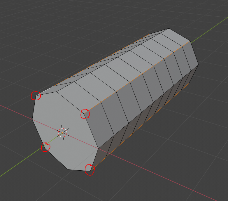
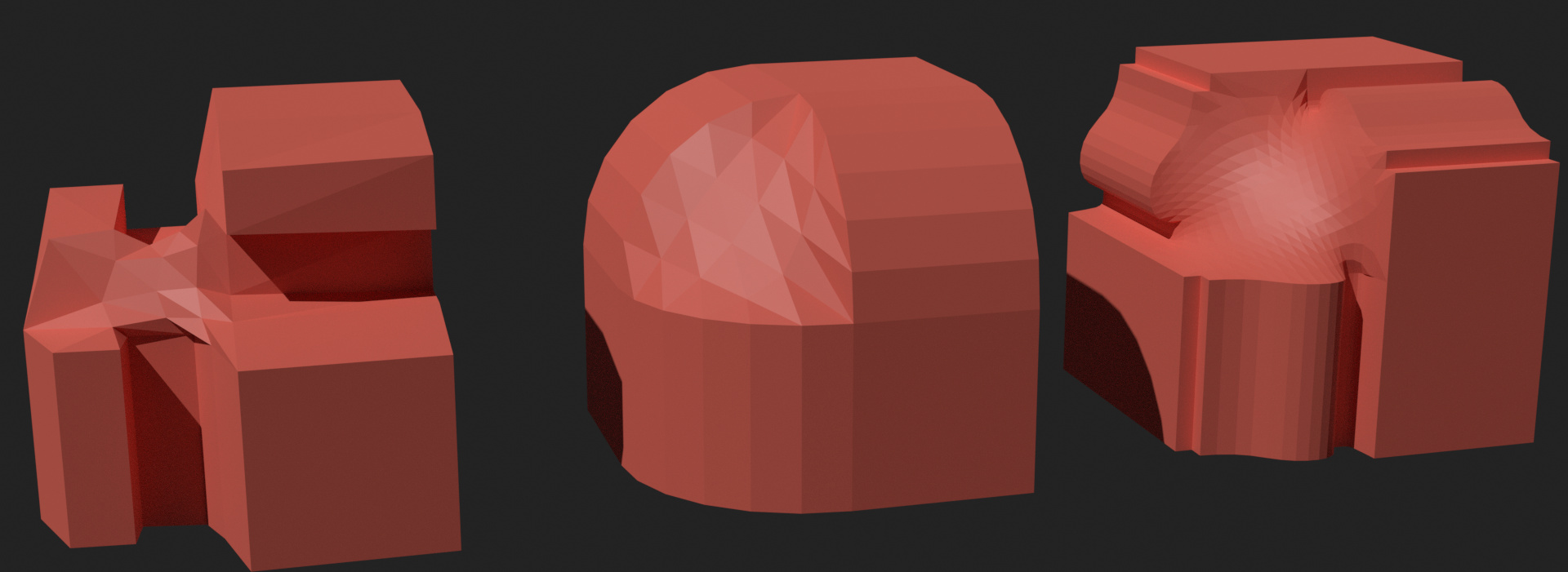
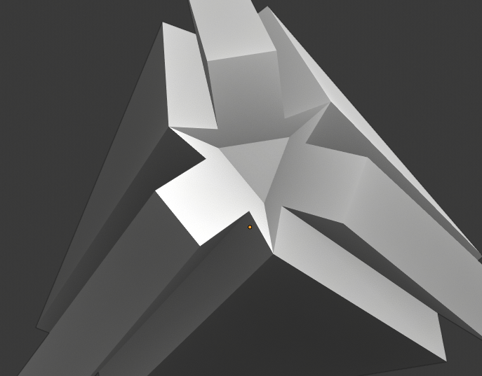
Hi everyone! I wanted to give an update on my thinking about creating the vertex meshes. I made some ideas last week, but over the weekend I wanted to try out some of my ideas manually to see if they actually worked. I used the corner of a cube as a simple situation, but keep in mind that the right method needs to work for all >3-way intersections.
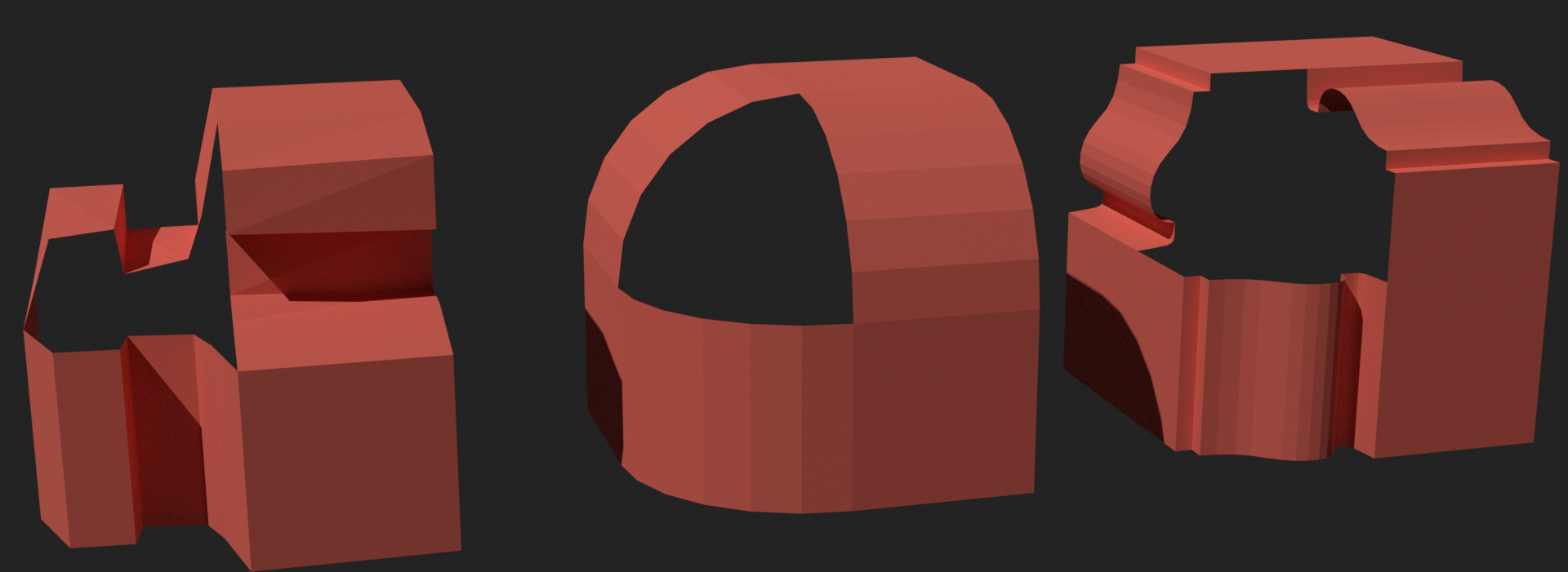
The best method should work in all three situations. The left is a simple profile with an overhang, the middle is a smooth “non-custom” profile, and the right is a typical use case that I’ve imagined.
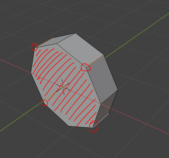
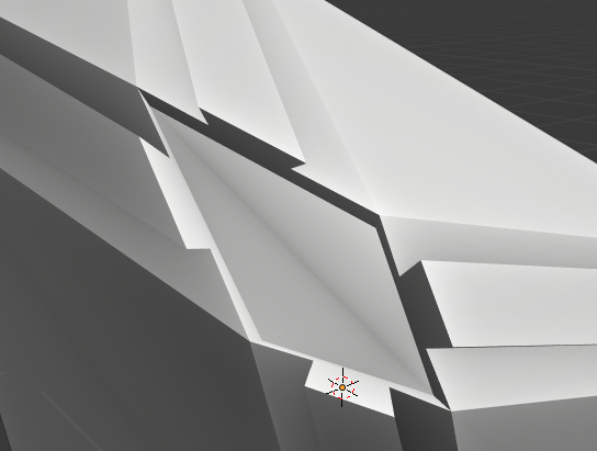
For this method I just filled the hole with F and then used the “beauty” triangulate option and converted triangles to quads. It works pretty well for the left, but not so well for the other two more complicated profiles.
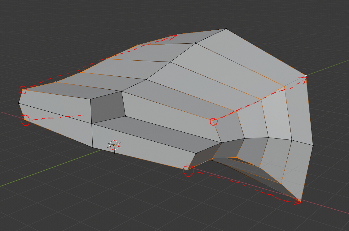
One idea I had is to reuse the profile for each successive “ring” of vertices. You can see the start of the method on the right. It works great for profiles that don’t have any overhang and evenly spaced points, but it didin’t work at all for the left example. I saw this method as the next logical improvement to the smoothed grid fill option, but I think I’m going to have to abandon this idea unless I come up with a way to improve it.
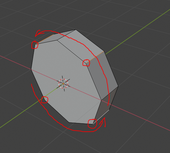
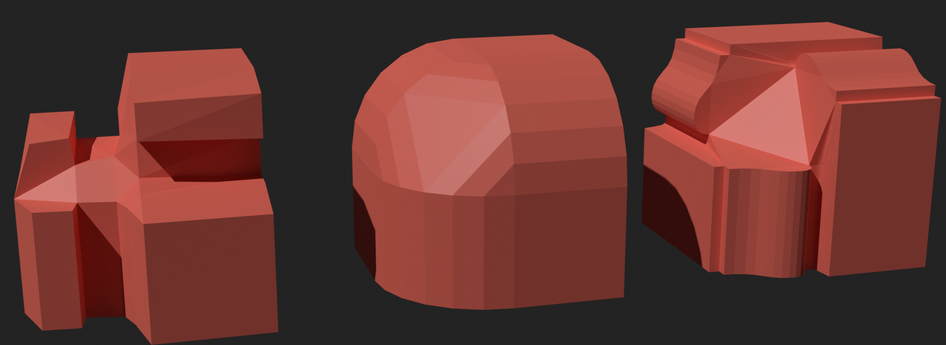
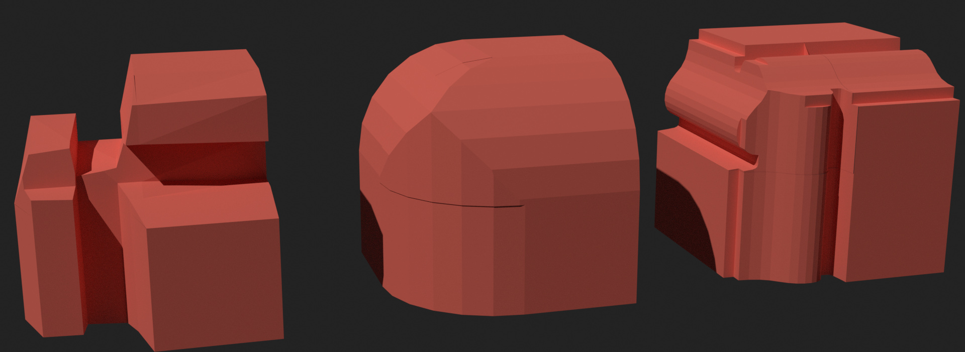
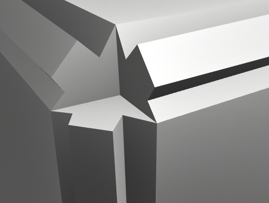
Here I used a grid fill to create the vertex mesh and then smoothed out the vertices afterward. This solution works ok in most situations, but it doesn’t look great, and it doesn’t emulate the real world at all. This solution is very close to what I have right now, although I need to fix some bugs before it starts to look like this. But it’s definitely the quickest to implement.
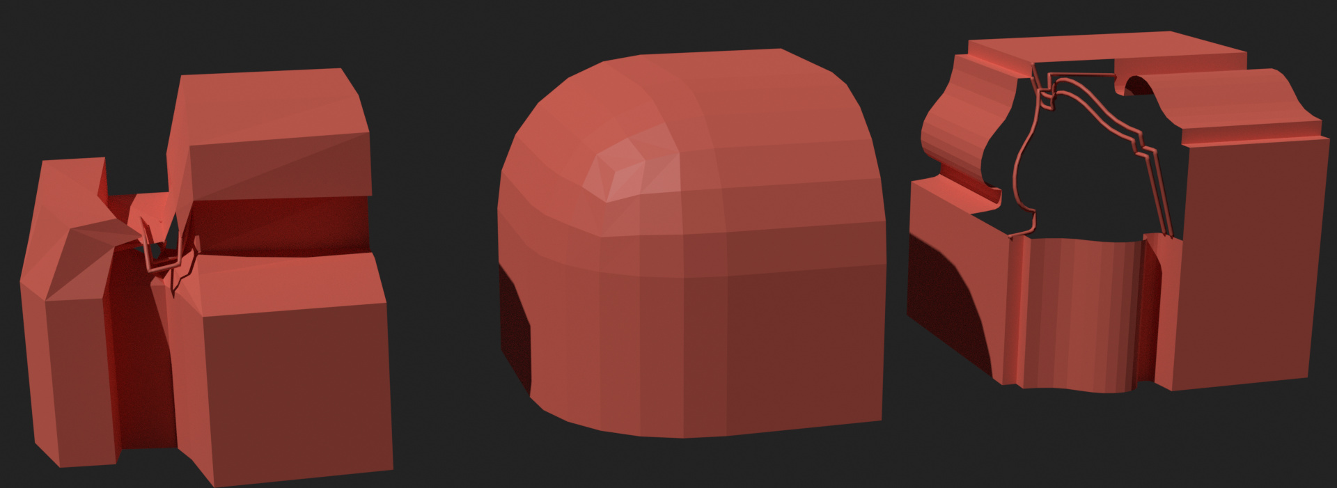
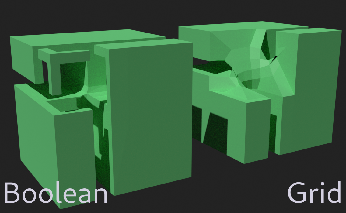
The unlikely victor for me was using boolean intersections with the corner profiles. It’s predictable, and it mirrors the real world, at least to some extent. It’s very finicky though, as anyone who’s used the boolean modifier knows. These small issues with Blender’s boolean operations might make it difficult to implement and frustrating to use.
Improving the grid fill: Close to finished already, but not close to the real world, and doesn’t work well with overhangs.
Implementing Boolean intersections: Much more of an unknown in terms of development, sometimes problematic, and produces islands with overhanging profiles, probably much slower, but is probably the better looking option.
the boolean version was actually a request in another bevel thread from someone.
So it would be nice to have it as an option!
But what’s the WIP image you posted in your weekly report thread?
Is that the grid version? Because that looked very good and imho (something like that) should be the default.
But for the extreme case you have above as an example the grid looks erroneous.
Yes, that was the grid option. I’m glad to hear you think it looked good, I was a bit worried people would find that too weird.
I agree with you that an option would be the ideal solution! I guess I can try to finish up the grid option and then see if I have enough time to add a boolean option too.
Hi. I agree that making an option to switch between multiple methods would be the best way to go. Also, the boolean method would be great as one of the options: it would sort of be consistent with how the 2-edge case is handled.
I also want to throw another method out there. If you end up with making an option that chooses from multiple methods, this could be thrown in to it
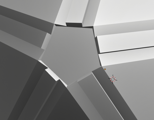
Cut-off method
Icosphere corner:
Tetrahedron corner (a sharper example):
Cube corner:
In this case, the ‘center’ face has zero area; it would be collapsed.
Wacky example:
Here, the center face is not flat.
Implementation: create the ‘center’ face. Fill each edge of it with the bevel of an edge, creating ‘profile’ faces. Position verts of the center face so that:
All the profile face are flat
the center face is exactly deep enough that a zero profile would not intersect it