Hi everyone! I wanted to give an update on my thinking about creating the vertex meshes. I made some ideas last week, but over the weekend I wanted to try out some of my ideas manually to see if they actually worked. I used the corner of a cube as a simple situation, but keep in mind that the right method needs to work for all >3-way intersections.
The Vertex Mesh Problem
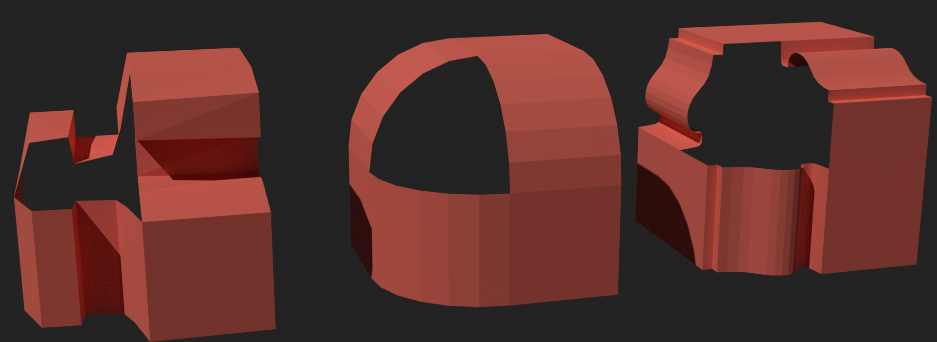
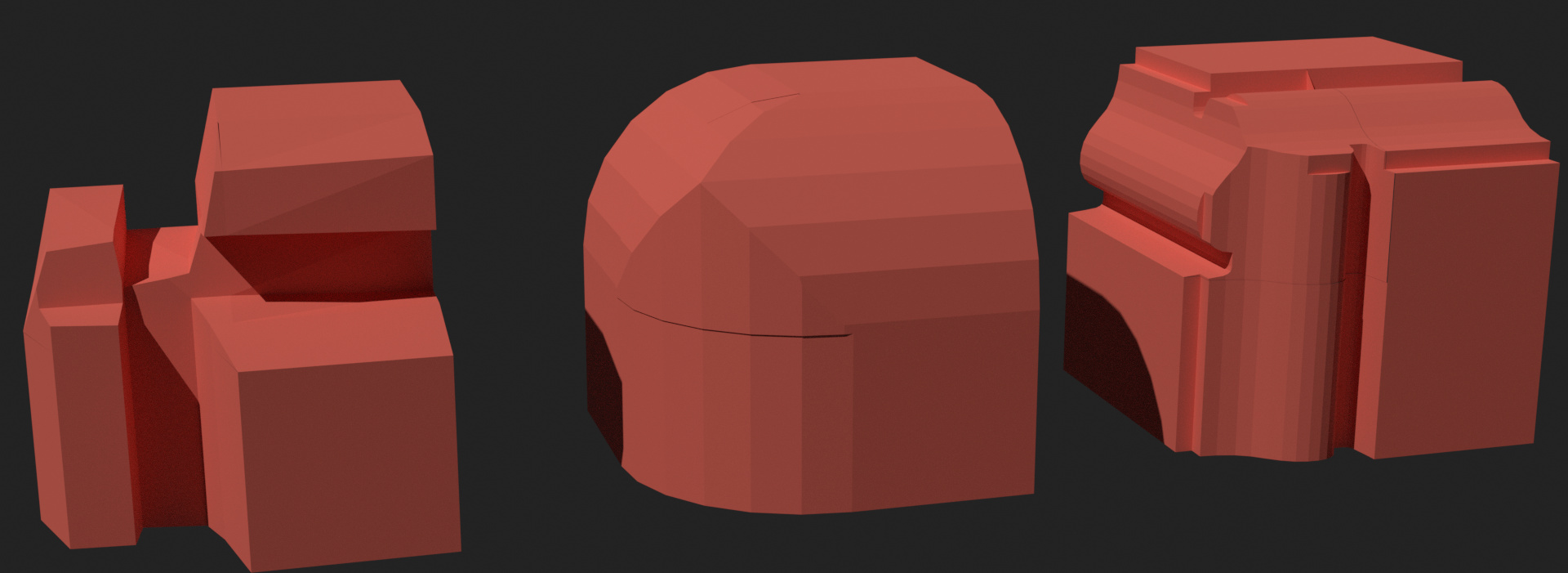
The best method should work in all three situations. The left is a simple profile with an overhang, the middle is a smooth “non-custom” profile, and the right is a typical use case that I’ve imagined.
Triangulated Fill
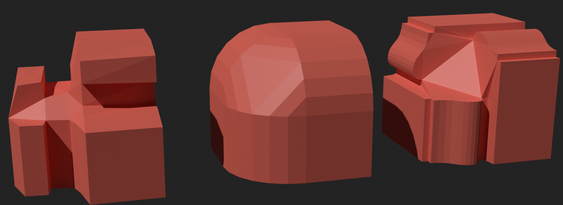
For this method I just filled the hole with F and then used the “beauty” triangulate option and converted triangles to quads. It works pretty well for the left, but not so well for the other two more complicated profiles.
Averaged Profile Rings
One idea I had is to reuse the profile for each successive “ring” of vertices. You can see the start of the method on the right. It works great for profiles that don’t have any overhang and evenly spaced points, but it didin’t work at all for the left example. I saw this method as the next logical improvement to the smoothed grid fill option, but I think I’m going to have to abandon this idea unless I come up with a way to improve it.
Smoothed Grid Fill
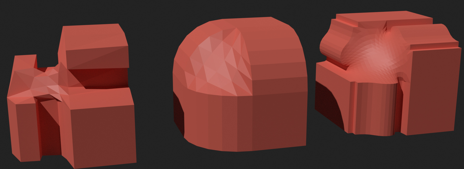
Here I used a grid fill to create the vertex mesh and then smoothed out the vertices afterward. This solution works ok in most situations, but it doesn’t look great, and it doesn’t emulate the real world at all. This solution is very close to what I have right now, although I need to fix some bugs before it starts to look like this. But it’s definitely the quickest to implement.
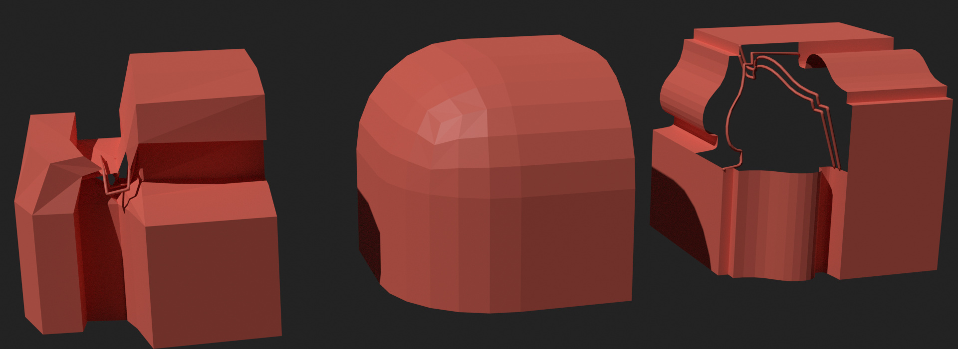
Boolean
The unlikely victor for me was using boolean intersections with the corner profiles. It’s predictable, and it mirrors the real world, at least to some extent. It’s very finicky though, as anyone who’s used the boolean modifier knows. These small issues with Blender’s boolean operations might make it difficult to implement and frustrating to use.
Conclusion
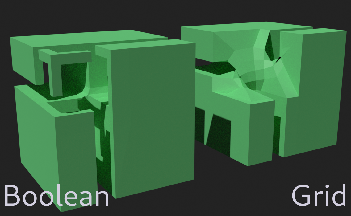
So in my opinion it comes down to two options:
- Improving the grid fill: Close to finished already, but not close to the real world, and doesn’t work well with overhangs.
- Implementing Boolean intersections: Much more of an unknown in terms of development, sometimes problematic, and produces islands with overhanging profiles, probably much slower, but is probably the better looking option.
Thoughts?