I agree too, I think It was a lot faster and more functional. But, with the geometry node project need to have an active node modifier for choosing the display in the node editor. As @slowk1d said, it can be an option in the preferences.
I have a question. Are you going to carry out modeling tasks in geometry nodes or are you only going to use modifiers in this concept, because I think that if you are only going to focus on modifiers perhaps the name of modifiers nodes is more accurate. If on the contrary you are going to carry out modeling tasks, it would make more sense to use geometry nodes.
1 Like
I think we’re looking at the word ‘Attribute’ through a looking glass and it’s gotten bigger than it really is. Attributes are just named characteristics associated with Blender geometry - things we have been using for years.
Consider the vertices of a mesh. Their positions in space are just attributes of these vertices - no more, no less.
Running with @Kenzie’s spreadsheet analogy (thanks for that!), we can take three columns, merge a spanner header cell above them and write in it the label position. Position is an intrinsic vertex attribute. It is hard to think about vertices without also thinking about where they are. We don’t attach intrinsic attributes to geometry: in the geometry node world, such attributes are already built in the geometry.
We may tack on another single column and label it weight because it pleases us to associate zero-to-one weighting values with our vertices. Intrinsic? I hesitate. I can think of vertices with or without weight. On the other hand, I can reach around/behind/beyond the geometry node world, go into Blender’s property panel and assign a Vertex Group, and that vertex group comes across to the node world as an intrinsic attribute.
Soon, ditto, Vertex Colors (but not yet). We may tack on four more columns to the right of weight, and write in this spanning header the label: colorwithalpha, referring to the vertex colors that we are also pleased to associate with vertices.
We may tack on yet another column and call it Foobar - it associates True/False boolean flags with each of the vertices. What the H, E, Double-toothpicks is Foobar?
I’m a lousy programmer and tend to write non-descriptive names. Presumably I’m thinking of a boolean mask attribute to group the geometry’s vertices one way or the other. In any case, Foobar is an extrinsic attribute. It didn’t come, predefined, into the node world with geometry. I made it up on-the-fly by tacking on another column, or - in the node world - writing it into an Attribute -X- node as an attribute operand.
What is a geometry set? To continue with @Kenzie’s example, it’s pretty much the entire spreadsheet that contains these attribute columns - no more, no less. The depth of the spreadsheet - the number of rows it has - is intrinsic to the geometry set. A mesh only has so many vertices; that count directly translates to the number of rows in the spreadsheet.
That a spreadsheet page of attributes has a specific number of rows is the reason we just can’t pick up an attribute column in one spreadsheet page and put it down in a spread sheet page of another geometry set. What are you going to do about the row mismatch? That question must be addressed by whatever the ‘pick-up-and-put-down’ process is: what I called an ‘attribute transform node’ in my upstream post. That process may decide to interpolate 27 rows from one geometry set to the 1,357 rows of the other geometry set. Or maybe fill in default values instead. In any case, we just can’t pickup an attribute from one geometry set and paste it into another without some idea about what to do with the mismatch.
Some of you may have caught my ‘pretty much’ weasel words when making an analogy between a spreadsheet page and a geometry set. What am I hiding? I confess. Meshes are more than just vertices. Edges connect vertices and winding loops of edges define faces. So the geometry set is actually a workbook of spreadsheet pages. For meshes, there are vertex, edge, and face spreadsheet pages. Geonode docuentation calls these spreadsheet pages domains. So, without the weasel words, a geometry set is a workbook with a number of domains, spreadsheet pages, each that have grouped columns of attributes that directly map, row-by-row and one-to-one, to the items comprising the domain, be they vertices, edges, faces, point cloud radii, or voxel density.
As you have probably gathered, attributes reflect a particular data arrangement, or types. Foobar: a list of True/False booleans. weight: a floating point in the range [0 - 1]. position a vector of three floats. colorwithalpha a vector of four floats.
As you have probably also gathered, geometry sets also have types, reflected by the number of spreadsheet pages - domains - that they have, alternatively, the Blender object they represent. Pointcloud geometry sets don’t have edges and faces, so its workbook doesn’t have those sheets, but it does have (sampling) radius as an intrinsic - and color too, so those sheets are part of its workbook.
I feel there are two broad sources of pain with Geometry Nodes, one representational and one operational:
- Representational: The node tree graph is struggling to represent interrelationships among things at different scale. Attribute nodes operate on ‘spreadsheet columns’ but transformational nodes like
Point Distributereads and translate entire workbooks. Yet someone who has just fallen into this rabbit hole beholds a node tree, sees attribute nodes and transformation nodes represented more or less with the same graphics, and that gives a false sense of equivalency. How to represent interactions among attributes - columns - on the vertex spreadsheet and face spreadsheet? How vertex, edge, face domains decorate attributes is not clear yet. - Operational: What I called ‘scopes’ in my last post - the region in a geometry node graph where one geometry set prevails - does not have many ways to convey geometric data to other geometry sets that need to operate on that data. Face normal attributes in a mesh geometry set may, from time to time, need to orient instanced point clouds in a distant scope - that transfer node does not exist yet. Do I open up a ‘drill-down’ graph - a node workspace within a node workspace - to construct that transfer node from math primitives? I don’t know yet.
Neither of these are well settled yet and erect brick walls. How this settles - and whether it settles sensibly or not - is a matter of concern. I strongly agree with @JuanGea that these issues have to settle in a good way, and that a rushed official release of Geometry Nodes - prematurely to make a big YouTube splash, perhaps - would probably not be a good thing.
10 Likes

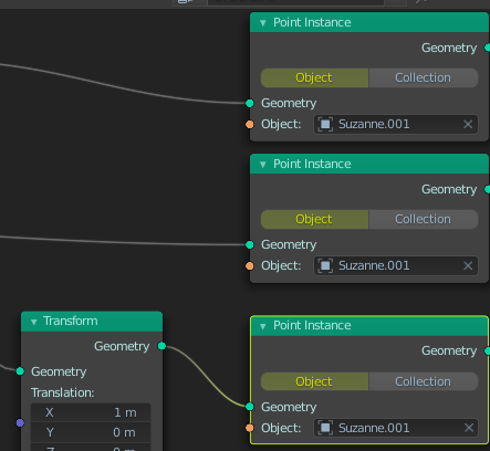
Missing Object input to distribute one to many
1 Like
Also there is no group input or output in Add menu. So if I deleted one, i will lose it and force to make empty tree and copy group input from it.
Also face instance will be cool too. It allows to rotate faces instead of final geometry, that can be very complex
Not sure what you mean here…
Also face instance will be cool too. It allows to rotate faces instead of final geometry
What gives the instance it’s orientation is a rotation or normal/tangent attribute. So we could have a feature on point distribute (or another node) to get the centroid of each face along with it’s orientation so we can further work with it as points and use the point instance node again.
I have already found the way to rotate vertices and instances: adding rotation attribute.
Great summary, and yes I agree with how you’ve described attributes. Yet in other node-based apps, even though there is the option to mix and do math ops between different sets of data, it should still be easy for any user without coding background to understand how to operate nodes.
In this sense, keeping “attributes” that define values, vectors, colours, sets, etc should be kept separate, preferably with separate attribute type nodes for each with a drop-down menu that shows all the possible types of values, vectors, colours, sets, etc.
The other confusing thing about attributes in their current state is understanding when an attribute represents a single value or a list of values. It should be very clear to user for both.
2 Likes
Attributes in their current state should always represent a list of values, unless there is only one vertex or point that is.
In shading nodes it’s different, with the “Attribute” node, but shading nodes are evaluated completely differently anyway.
1 Like
Awww, gee… It’s my wont to figure things out by writing things down. If my notes, however “provisional and tentative” they may be, serve better than to just bemuse and confuse, then I’m glad — and relieved. Thank you.
Perhaps, when selecting a node, a table appears in the righthand sidebar listing attributes visible to the node and available in the underlying geometry set, giving their type and associated geometry set domain — but I’d settle for a simple drop-down menu.
Apropos of nothing here, I took a brief and illuminative romp through your youtube channel and took in your BCON2019 presentation. Being one to regard buildings rather as gadgets to keep rain off my bald spot and warmth in the room, I am very glad that their are architects who better such prosaic notions.
1 Like
I just wanted to echo this. There would be so much more possibilities even in these early stages if we got access to individual points’ locations, id’s etc  Just a simple “point info” node, alongside the “object info” one?
Being able to make these basic controller-driven effects without being limited to the weight proximity modifier, for example:
I imagine it would be very beneficial for the scattering workflow, too?
5 Likes
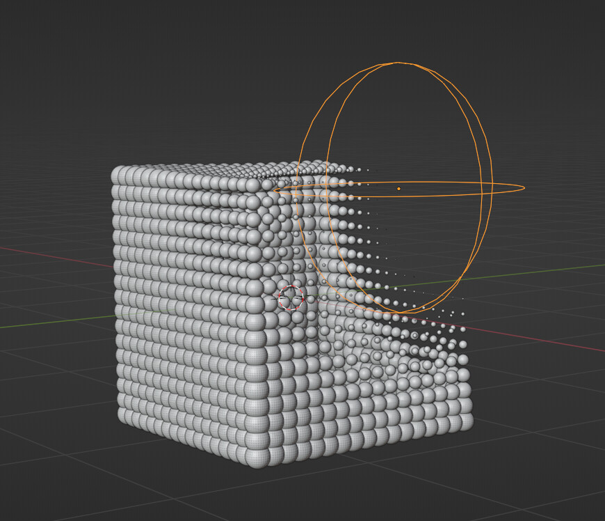
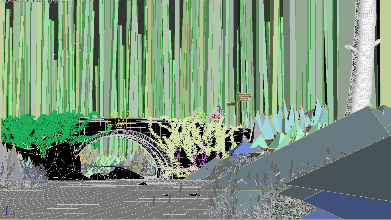
In the viewport, there’s a culling effect on the point for a smoother display! this is great
But sadly:
- once the point are instances this optimization is no longer here
- it seem that user cannot control this culling effect ?
when working with extremely dense scattering, with a lot of instances, an optimal display solution is needed. Point density culling within the viewport might be a good idea
5 Likes
I don’t understand this point, once the instances are true instances this should be a fairly moot point?
Might be nice to be able to create and define impostor objects for distant LODs though.
Maybe a silly question, but is it possible in any of these systems (Geo nodes, svershok or sorcar) to bake/export the result into a new geometry object?
Or cache animated results?
1 Like
Currently, you can apply Geometry Nodes modifier and obtain a mesh only for non-complicated nodetrees.
When you are instancing : applying modifier does not work.
Trying to make instances real is a failure, too.
But I succeeded to export a satisfying alembic file. That is not bad for something in development.
For mentioned addons that have years of existence, I don’t use them. I was using animation nodes.
But the need is probably satisfied.
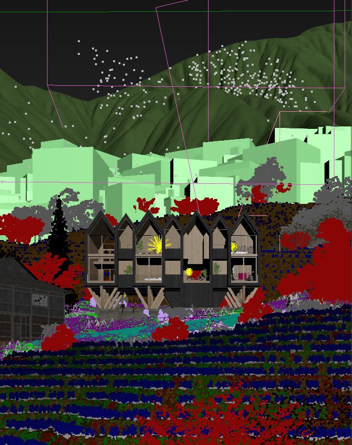
If you need to scatter millions of objects, even instanced geometry is going to destroy your gpu. That’s why we need some sort of optimization/culling functionality for the viewport. Hopefully it will come soon, I can’t imagine how they would create complex environments for Sprite Fright without it.
3 Likes
With bounding boxes straight from the 90’s 
3 Likes
Some examples on how other soft handle viewport when scattering dense scene.
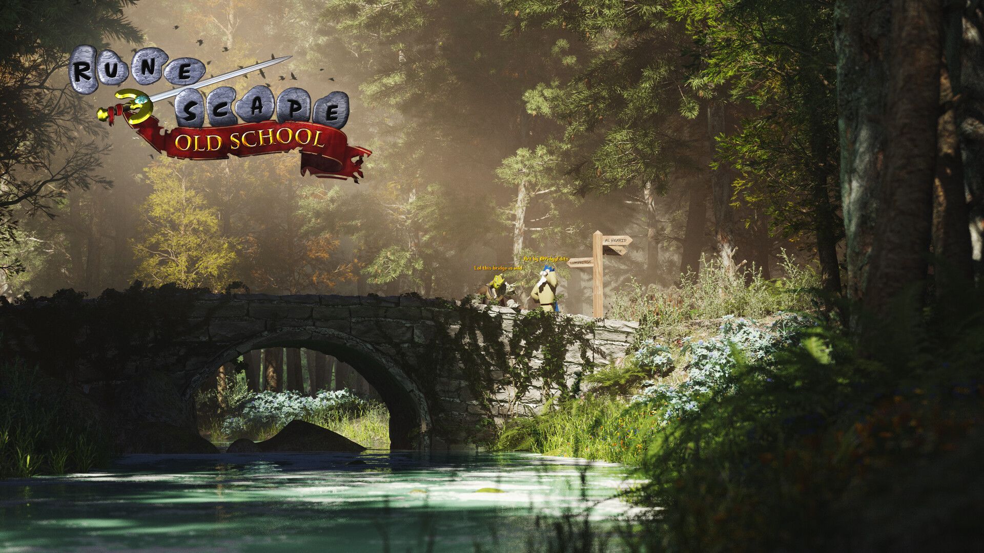
even better would be some proxy display option or distance driven LOD
With the Scatter addon we did try point cloud display, but this task might be too hard for python. As for Proxy, Lodify do the job imo, but this kind of tech should be built in
Maybe all that display tech will comes later
12 Likes