I like it a lot! And now that the dashes are even-spaced and not fully transparent, I personally don’t even need to turn them off honestly, they help to quickly distinguish between geometry, fields and single values. I think that colors are useful too to see implicit conversions and spot if the node you have selected has wires connected on it.
I played with the build and sketched a quick ocean effect:
One thing I haven’t been able to figure out in the new system is UV coordinate generation. In the attribute workflow I could just write to the correct attributes I think?
It would be nice if there was a ‘UV’ input, analogous to position. I’ve been busy generating ropes using a curve primitive and I’ve gotten some very nice results, but I’d like to map the UV coordinates around the curve in a smart way and I can’t seem to find how to do it.
Is UV coordinate manipulation from GN supported/planned? Do I just overlook something obvious?
What I meant is it can’t be a color anymore, now that color communicates data type. And when it’s disabled, only the node outline remains… which seems a little light to me
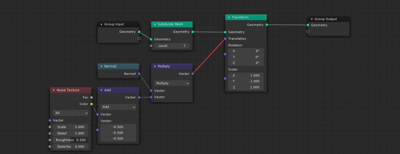
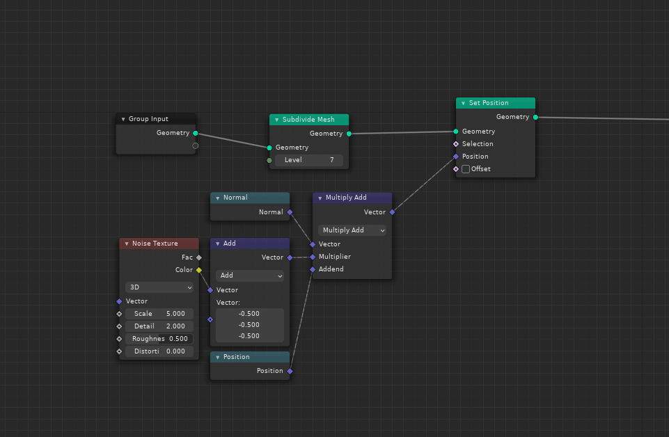
But it still makes very little sense. Transform node implicitly adds the position input to the existing positions, while with set position, user has to do it explicitly. Of course it’s fine to have set position for more specific tasks, but for a quick, simple vertex position transformations, I don’t see a reason Transform node couldn’t take in a field.
So? Why shouldn’t we have an ability to transform volumes with fields too?
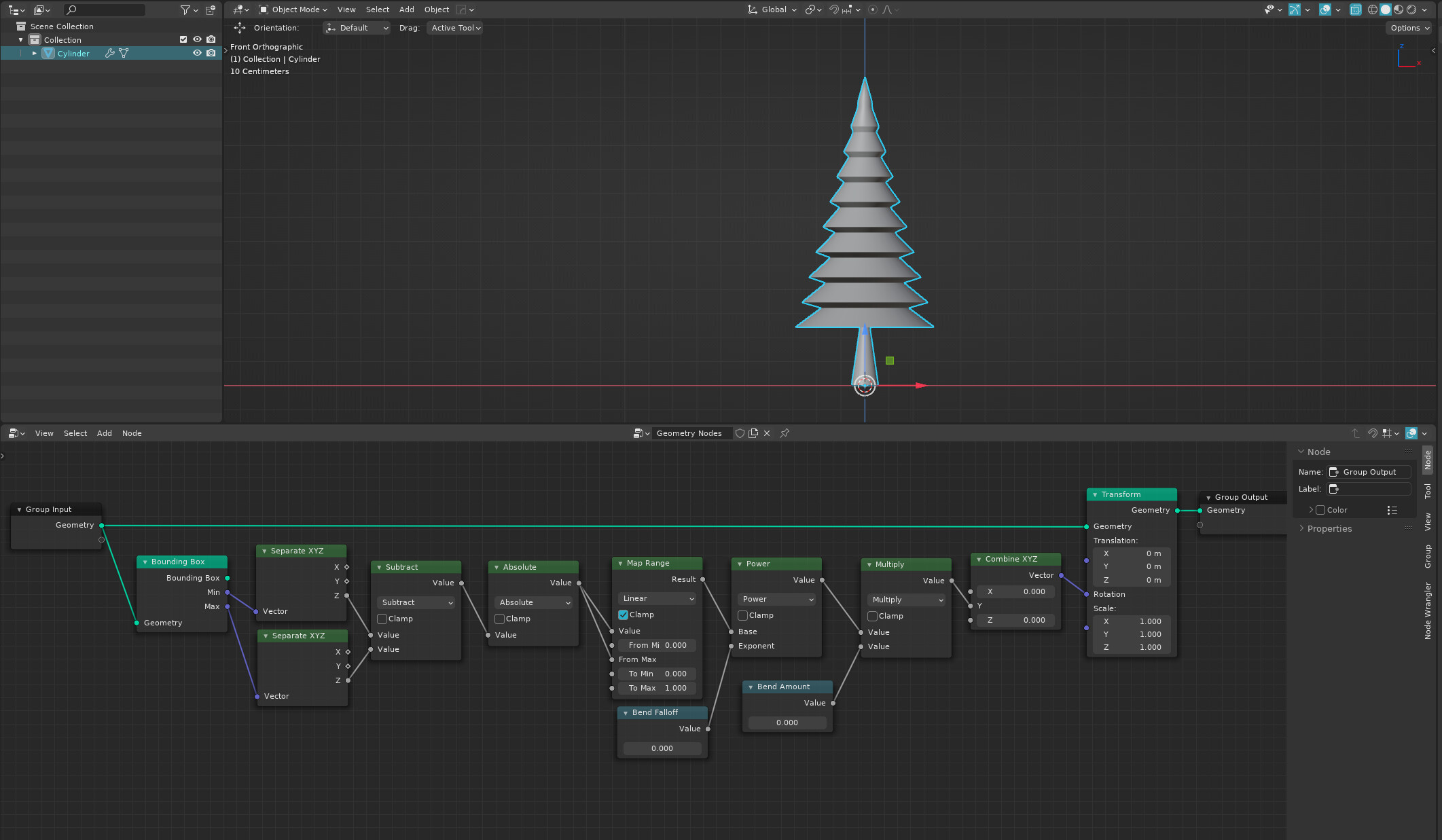
Here’s a practical example where it’s an issue. Let’s say I want to bend a simple tree model. If the transform node correctly accepted both fields and constants, this is how I could implement a simple bend with amount and falloff control:
Because Volumes are not yet properly supported I guess? Like the spreadsheet doesn’t even show volume data, it does not even have a domain for volume yet. If you try Set Position after Points to Volume it’s actually not gonna work.
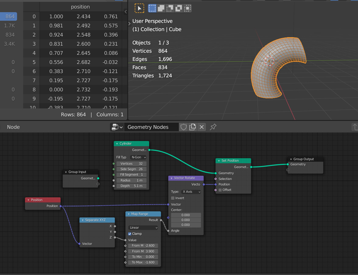
Not sure I understand how it works, but if it’s about rotation, Set Position can do the rotation by using vector rotate with the position field node
Yes, I am aware it can be done by set position too. It’s not really a dealbreaker, but a matter of workflow. To more universal the nodes are, the better.
If you check the “Offset” checkbox in the Set Position node, you don’t need to use the Position input any more. Then it’s identical to the translation in the transform node. Note that the transform node might support fields in the future, it’s too early to say.
Yes, I noticed it shortly after, however it still applies only to position transform, not rotation or scale.
Again, not saying it’s a big deal, because all of those operations can be done in other ways. But at the same time, if Transform simply supported fields, some of those operations could be done in cleaner and simpler way.
On the one hand, I can understand protecting the beginners from themselves by defaulting empty position socket to original geometry position field, instead of 0. That way, if a noob adds set position node, their mesh doesn’t disappear as the vertices do not collapse to the mesh origin immediately.
On the other hand, the same default value is also used when offset is enabled, so enabling offset basically scales the geometry * 2, as it adds existing positions to existing positions once more.
The first obvious solution is changing the default behavior of the unconnected position socket depending on whether offset is enabled or not, but it can accept a field too, so that’s tricky.
In general, this introduces a bit of uncertainty what the default implicit values of unconnected sockets are.