yes, please… must have feature.
I realized that sample curve samples the entire curve, which means that I can’t have several disconnected spline segments in the same object and sample a given length/factor on each of them; instead the node returns a single position (in my case, somewhere on the first spline segment). Some other nodes such as resample curve resample each spline segment instead.
Yeah, that’s a design mistake on my part that’s hard to correct without invasive versioning: T92474: Allow choosing spline index in sample curve node
I’m hoping to support that when porting the node to the new curves data-block.
4 Likes
Ooooh I had seen that task before but didn’t understand what it was about at the time. Alright then. Thanks for keeping this in the back of your mind. Meanwhile it’s not a dealbreaker in my case, I can just use several curve objects. Cheers !
By the way can I ask for a little clarification ? does spline refer to a “curve segment” in the context of geonodes ?
Sure! “Spline” is a word we used because we need a different word from “Curve” to describe a single curve that’s part of the object data. We couldn’t use “curve” because then there would be no way to tell a single piece apart from all of them together. In the theory, sometimes a “Spline” is several curves connected together, but the terms aren’t used consistently at all, so the distinction is arbitrary.
The new curves object data type is called “Curves” for this reason, and a single “curve” is just called a curve, so there will be no need for the confusion. The downside is that we’ll have to rename nodes and sockets (again, in some cases). That’s unfortunate, but it’s still for the best I think.
1 Like
Gotcha… so now it’s a “curveS object” and a single piece is just a curve. Makes sense. Cheers !
I have encountered a weird behaviour, not sure it’s a bug ? the fill curve node automatically flattens the geometry on the ground (Z=0). I was playing with a translate instances node placed before a fill curve node and no matter how much I moved the curve instances on the Z axis, they would end up laying flat on the ground. Placing fill curve before translate instances solved the issue. Is this supposed to happen @HooglyBoogly ?
The curves in question came from a string to curves node if it happens to be important.
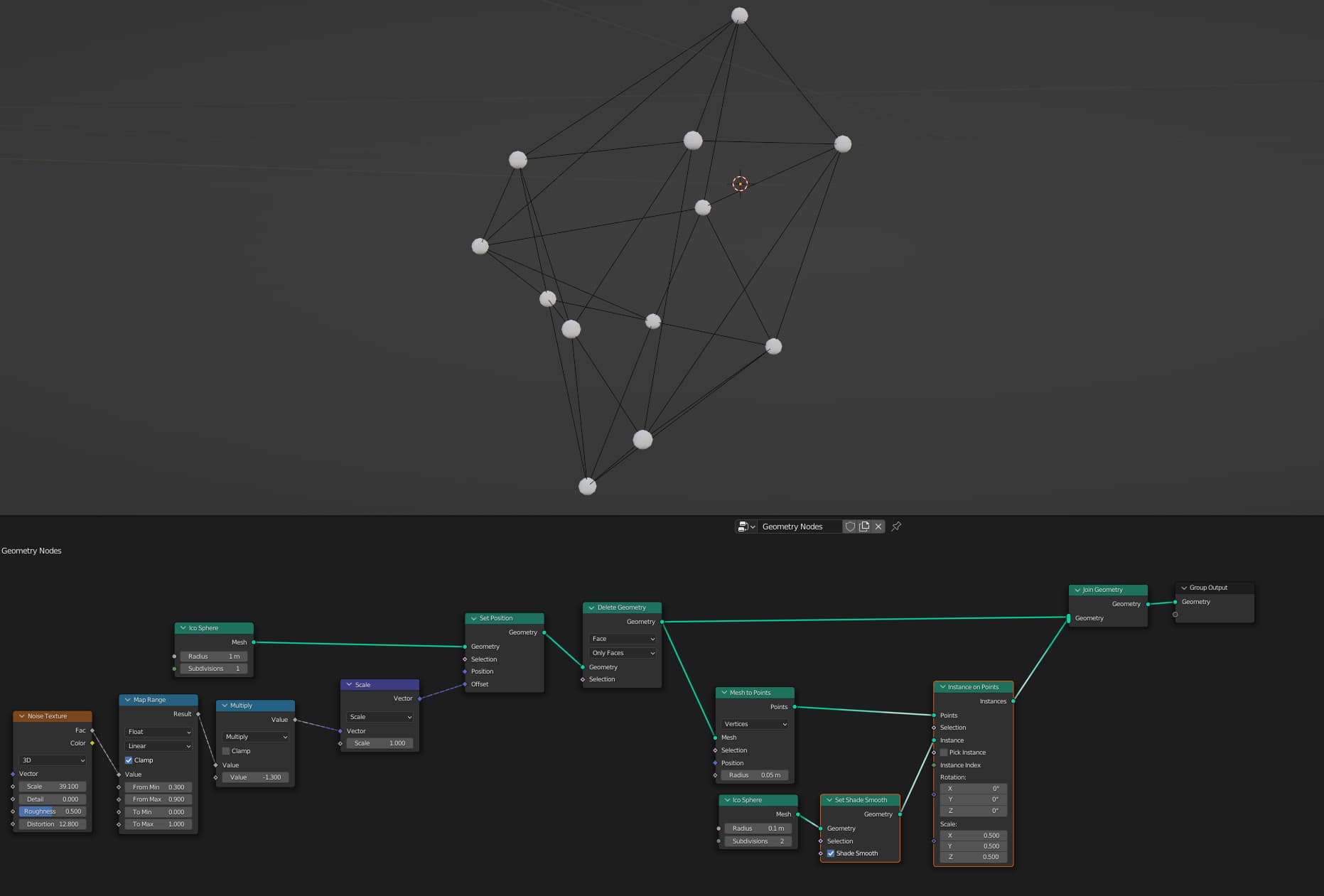
Hi there! I have a sphere with instances distributed on its faces. Now I want to be able to select a slice of the instances and I would like to be able to control it dynamically e.g. with a ColorRamp. My thought would be to use the Selection option of the Instance on Points node and maybe use Position field as in my pic but I can’t get the desired, dynamically adjustable slice of instances. Any suggestions?
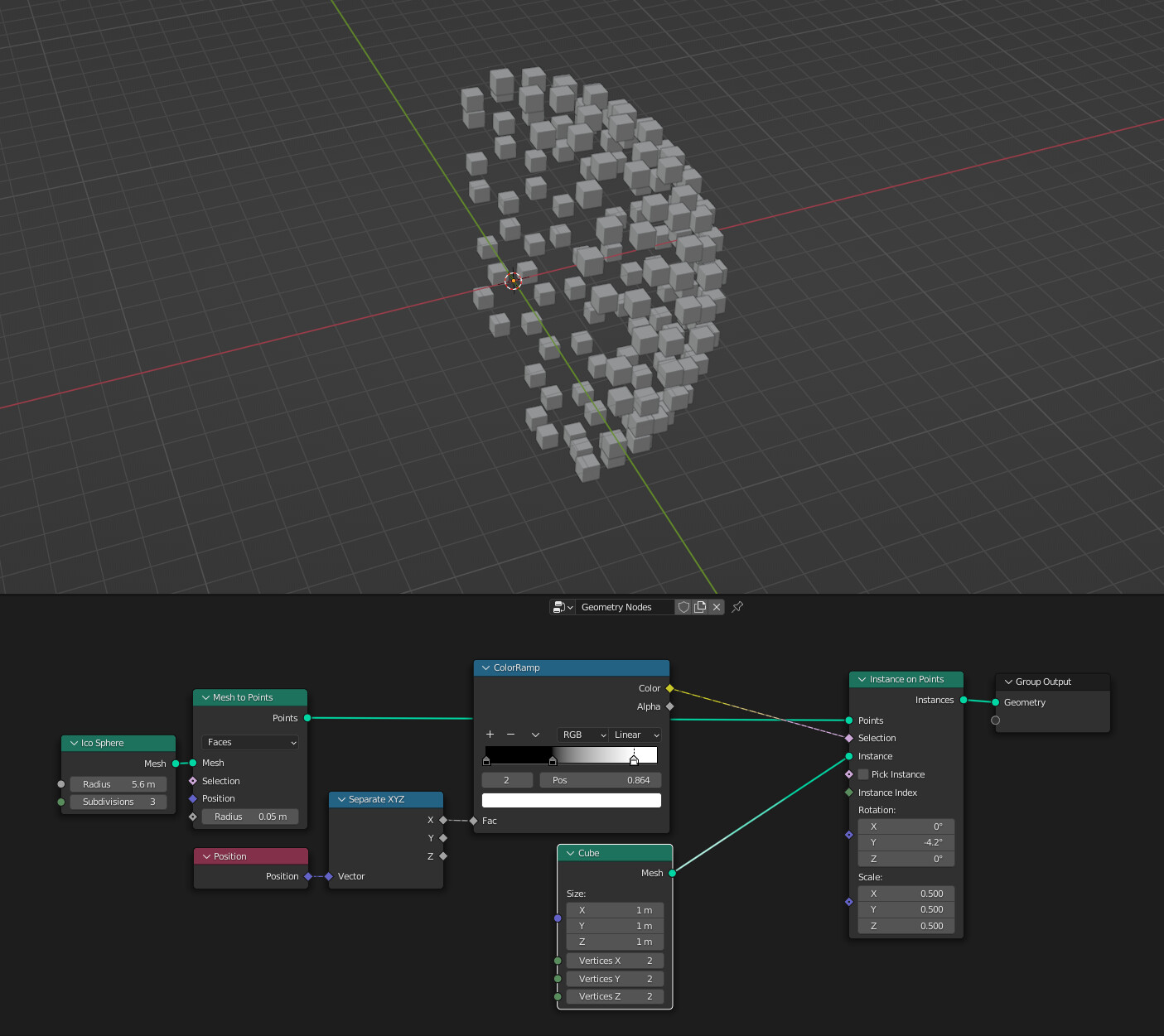
Thanks!
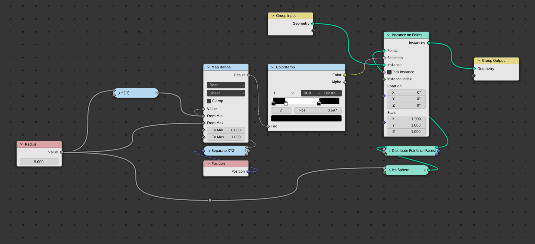
The icosphere spans over
x ‘in’ [-1,1]
But your Colorramp only handles [0,1].
You can only select half of the sphere that way. To be able to select along the whole sphere, you need to remap …
[-1,1] → [0,1]
You can use a MapRange node.
You also can use constant interpolation for the Colorramp.
1 Like
Leanard, thanks for your fast reply!
When I Pug the radius into the Ico Spere it gives me an error (red connecting line). Whats is the node is (-1)? Math node?
I try to keep most nodes minimized and edit them from the n-panel. It helps me to give a node a name which describes what it does.
The * (-1) node is a math node which multiplies its first input by (-1).
You wrote …
When I Pug the radius into the
Ico Spereit gives me an error (red connecting line).
Sorry, my mistake. The Radius node in my example is a renamed ‘Input/Value’ node.
It is not the ‘Input/Radius’ field input node.
1 Like
Oh thanks! It worked 
1 Like
Here comes my next question:
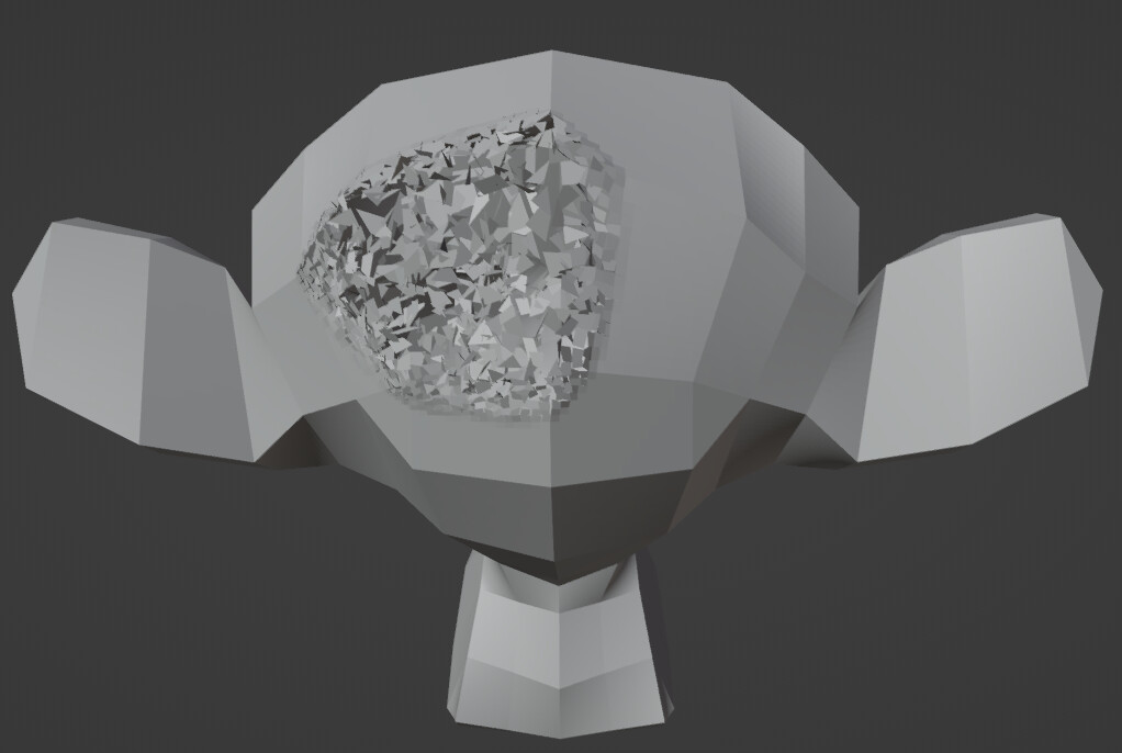
I have two Susanne objects
- A normal looking Susanne and
- One that at some part has distorted faces (see pic)
How can I compare the position of the faces of the two Susanne’s and then select the faces with equal positon. My guess would be to use the Position field, Capture Attributes and then a Comparison node. But I can’t really get it done. Maybe a different field? Any ideas/suggestions?
Thanks!
1 Like
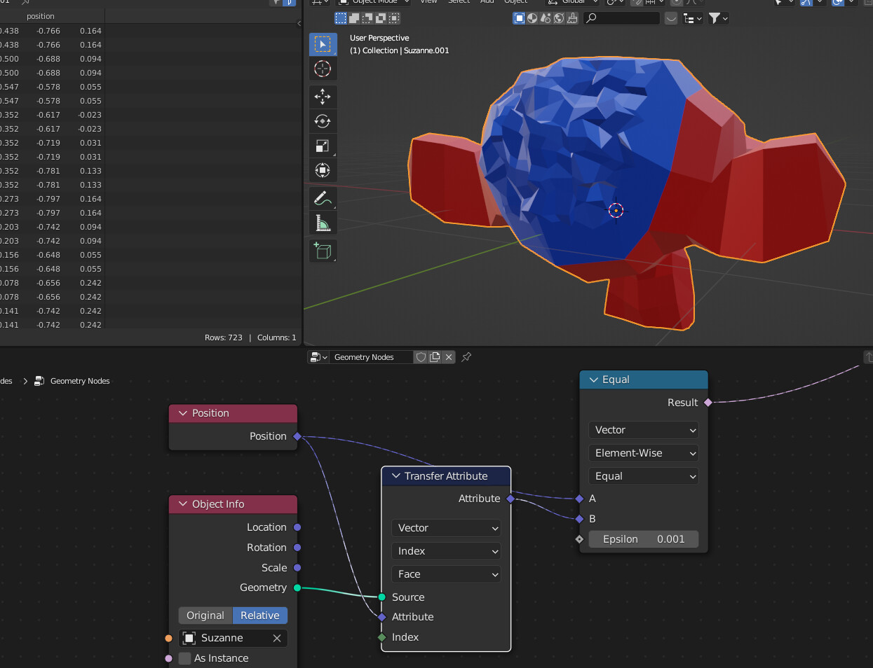
That is correct. And for extra understanding: all field data (including attribute data) only has meaning coupled with a geometry. So to compare two attributes of different geometries you first have to transfer them to the same geometry.
This is easier to understand if you consider that the equal node loops over the (domain of the) geometry it connects to (on the right). So it needs data for each point of that domain.
When a node has an ‘attribute’ socket the data that flows over the dotted line is not the attribute data itself (i.e. it’s not an array of numbers or vectors), but just the internal ‘name’ of the attribute. The attribute has to exist on the current geometry to be able to use it. Hence the need to transfer the attribute data to the current geometry before comparing it.
1 Like
Hello, guys.
Is there any way of instance several objects and each one have its own texture? I’ve tried to search but I only find two ways: using a material index, which randomize the materiais per face, which isn’t ideal, or using several objects (each one with its own texture) and then instance the whole group.
But the question is if I can have one object and randomize several textures on this only object. Thanks in advance!
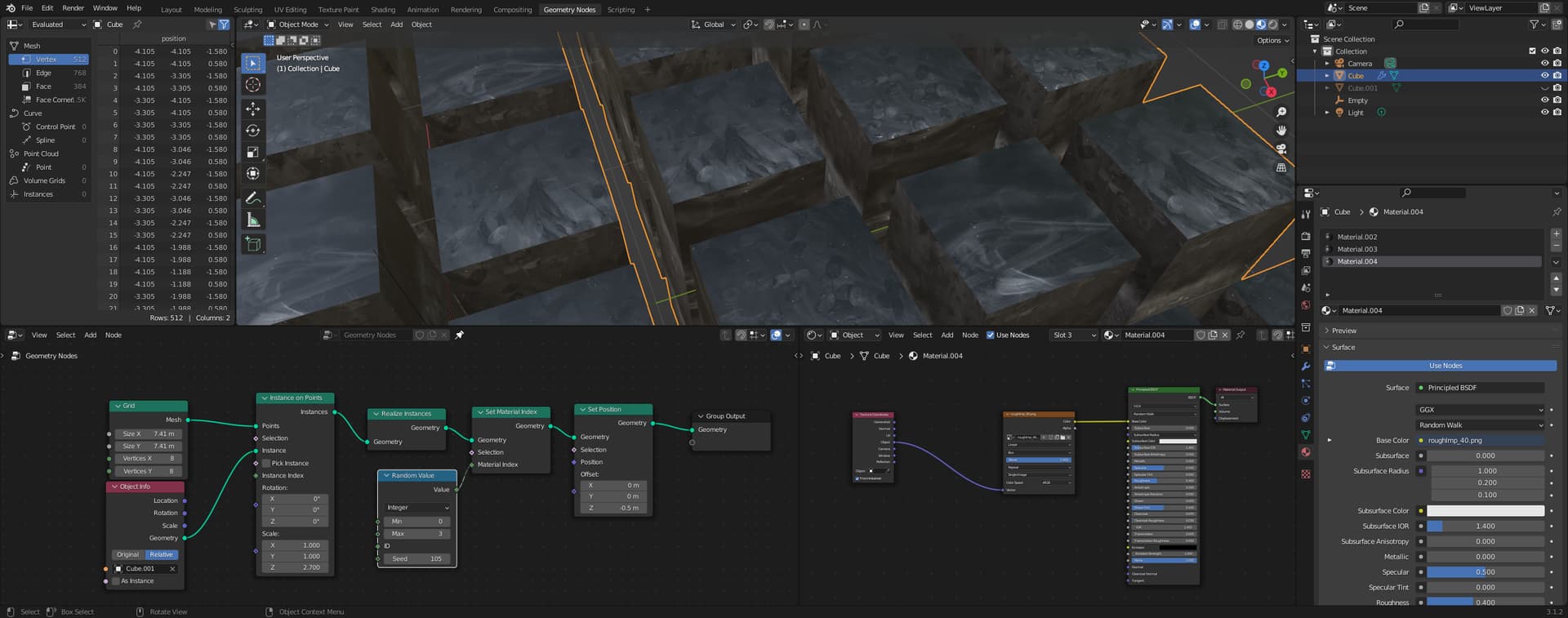
Or even better: I could use just one texture instead, but randomizing their vectors/placement to make each instance to have some part of that texture (with different locations and rotations, for instance). The issue is: how to do it?
1 Like
I thought you might find this file useful:
https://pasteall.org/blend/67ddee8e990846dab313c97734adc6ee
It allows you to:
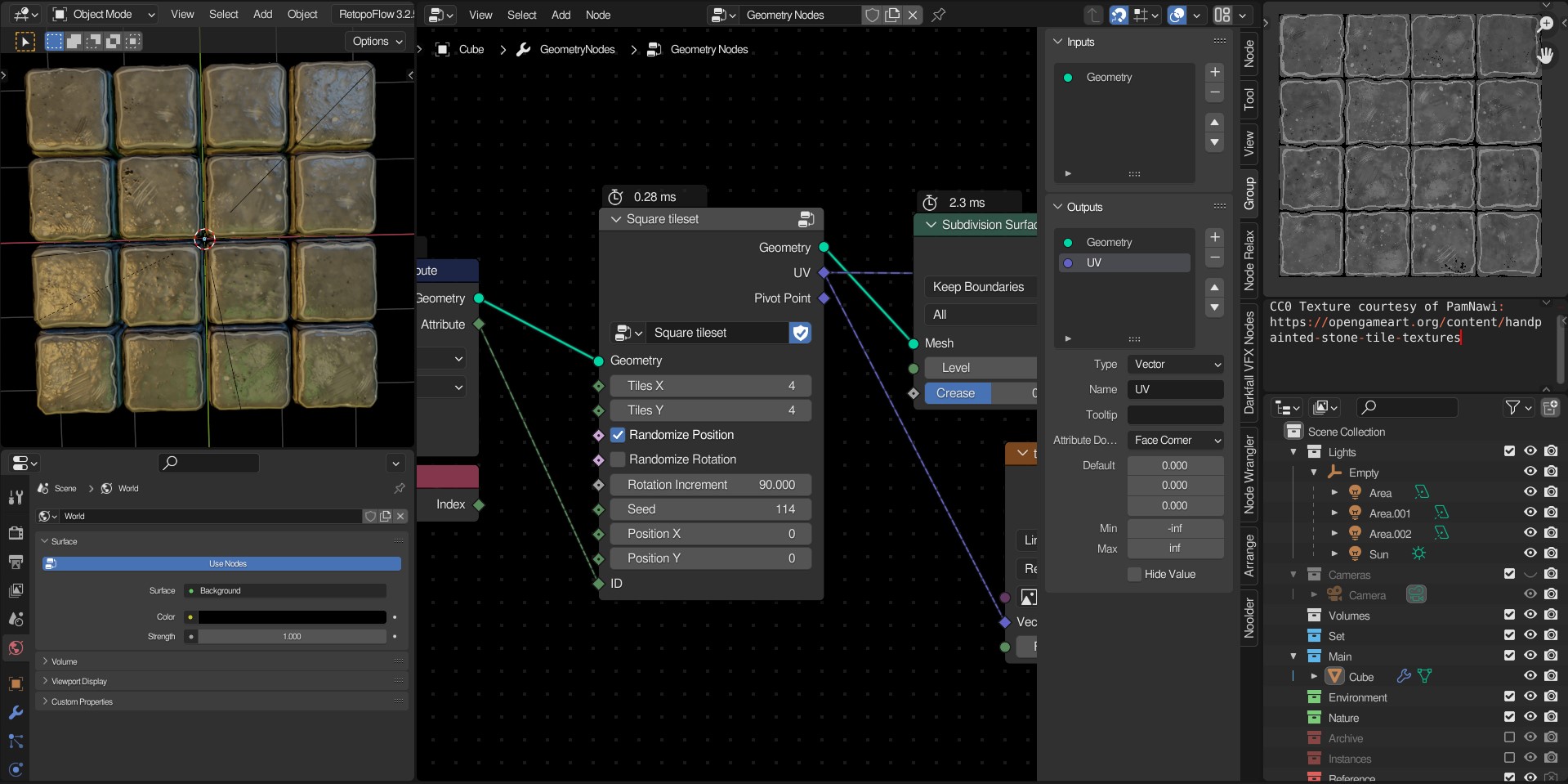
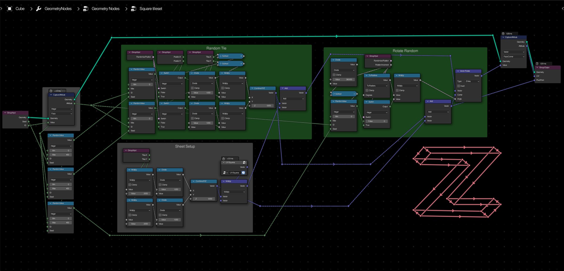
- Use a texture of any size, as long as the tiles are constant.
- Randomize each tile based on the given index.
- Randomize rotation of each tile. (Works best with square aspect ratios.)
- Use a custom ID for randomization. (such as mesh islands)
Make sure to set the texture’s X and Y tile count in the node to ensure the uvs are mapped properly.
The test texture is by PamNawi on opengameart.org.
Thanks to @higgsas for help with the UV squares group!
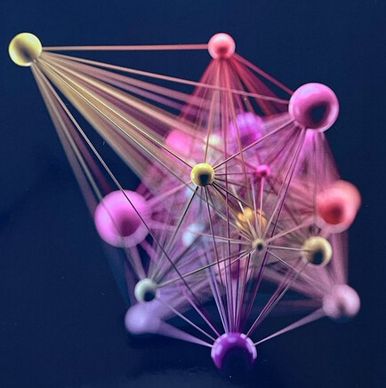
Hi there, I’m trying to recreate this in Blender (first pic). I created a node tree, but i don’t know how to add multiple lines between several instances in GN (see second pic). Any ideas? 

Works like intented! Thanks  Is there a way to increase the number of lines and randomize the line’s thickness?