I get how this works.
The big plus is, that it’s simple. it’s simple to link a value to the gizmo. And once you get it, you get it. However, It just feels in conflict with the left-to-right design rationale of blender nodes, because intuitively you wouldn’t think that the node on the right can affect the output of the node on the left.
If there is a better solution possible, it must be exactly as simple…
1 Like
Hi, thanks for working on this !
I like the idea of letting the actual nodetree transform the gizmo. What are the cases where it doesn’t work? when fields are involved?
Let’s see how assets turn out with these gizmos, but I suppose it’s the responsibility of asset creators to not overload a given asset with them. If toggling is necessary at one point, it can be done from the dedicated viewport popover. Are you thinking of a per-gizmo toggle, from the modifier/nodegroup interface?
Nodes probably need to expand the “info” zone where they currently display the number of attributes used and the timings. We could show the gizmos in there as well as any actives caches. If we choose to cram it in there though, the overlay should probably show only on request, a bit like we inspect sockets right now. It would be too busy if we had to show it all the time.
I suppose so it always plays nice with the default themes and backgrounds. I think the idea is sound, but the gizmo palette should be largely extended.
How would you handle conficts between a value that’s both defined procedurally and connected to a gizmo?
I’m not sure I understand why other nodes that manipulate floats aren’t supported by gizmos? shouldn’t they work, as long as they’re not fields? how do you intend to communicate that only some nodes in certain modes work?
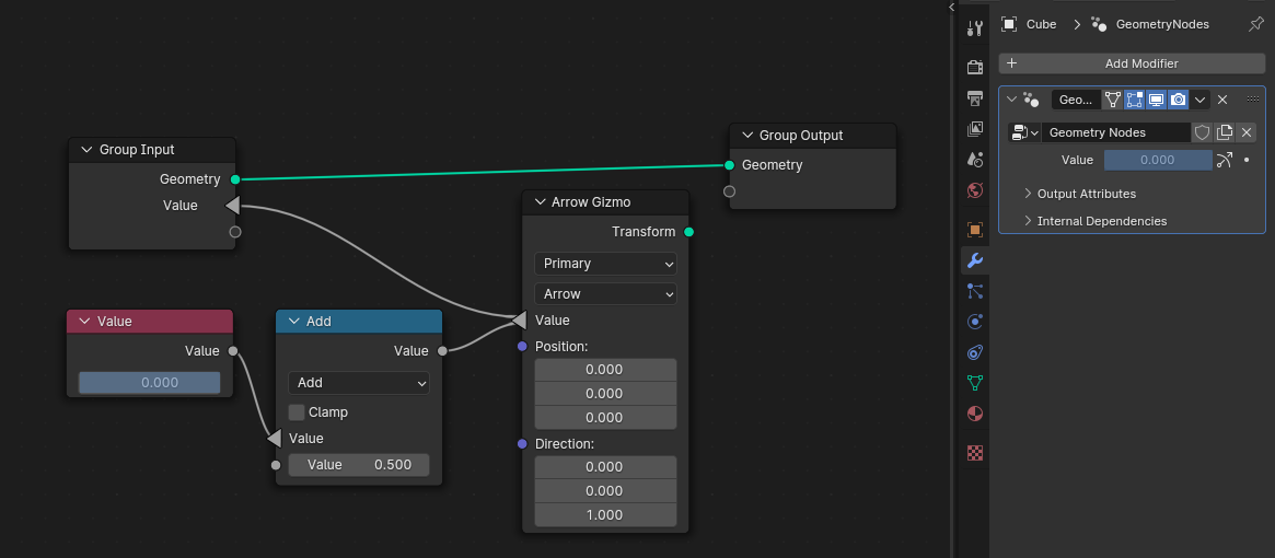
I think that’s a good suggestion. I don’t think ALL the wires need arrows (both left, and right), but in a case like this where it’s going backwards (just as is shown in the mockup) it will certainly make things less confusing.
I understand why it’s going backwards, but this is different than every established GN thing ever. So a visual cue will be beneficial.
2 Likes
Is the gizmo value being input instead of output for aesthetic reasons (to not have to wrap reroute node back around in the opposite direction) or is there also some technical reason/limitation?
1 Like
Great stuff I tested the build, and I like how easy it is to use. ![]()
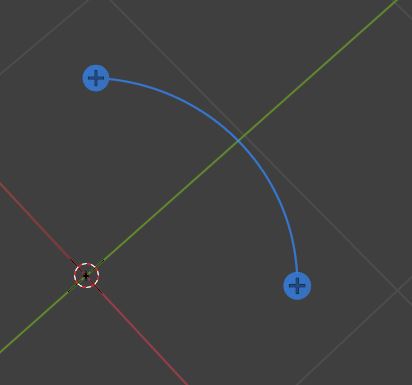
Will numbers of the values being changed be an inbuilt part of the gizmo? Seeing the value number as the gizmo is moved with subtype - factor, angle, time, distance, percentage. Would be great to not have to do workarounds like string to curves nodes like this.
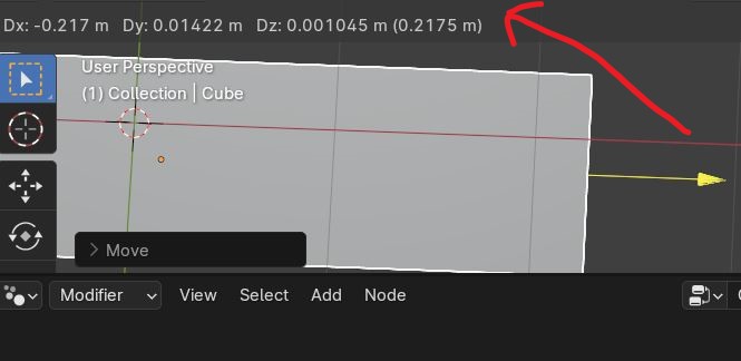
When we move an object normally in blender, the location coordinates appear in the top left of the viewport so perhaps the value the gizmo uses could appear there when moved.
A gizmo I would also like to have as a node is something like the spin tool in edit mode. Good for bending objects open closing books or choosing angles etc.
3 Likes
This is well thought and fantastic
Do we have to show which input values have a gizmo and if yes, how?
i think the answer could come in the form of some “gizmo” icon with a number next to a slider
clicking it could open a list of gizmos that are modifying that slider and clicking each could select that gizmo and focus/navigate to it (if nested)
or maybe more simply an icon that when hovered lists the gizmos in a tooltip
would be useful within large node groups and also on their outside, for gizmos connected to group inputs
making the icon clickable also open the door towards potentially hiding and showing the gizmos manually
on a different note, i fully support the idea of named gizmos for accesibility and to think of a future where we can see a list of gizmos and know what they do, in order to for example show or hide them
Could Arrow Gizmo and Dial Gizmo be renamed to something else? For example, Linear Gizmo and Radial/Circular Gizmo.
since their appearance can be changed within each node, i think they should be named according to how the user interacts with them. so Linear/1D and Radial/Angle make the most sense to me
1 Like
Seems to me that It is both: an input and an output. Bidirectional. The “Value” node changes the value of the gizmo, and the gizmo can change the value of the output node, depending on which one the user is editing.
Perhaps what this needs is a new Socket type, that is neither an input, nor an output, but a link, that conveys that the exact same number box is displayed and editable in multiple places.
Something towards this maybe?
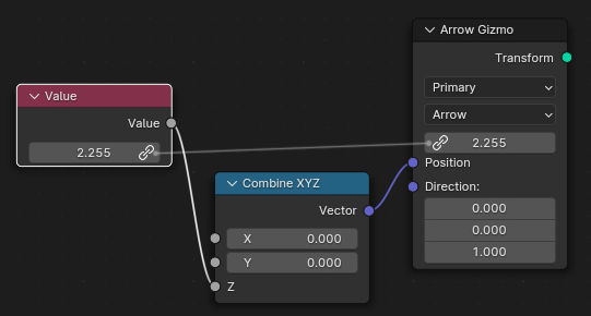
Just brainstorming.
9 Likes
Will auto keyframe work on the gizmo in the future ? for now we have to " insert key " each time we use it.
Also selecting the node each time I needed to see the gizmo felt like slowing me a bit, maybe we should have an option to always show it ?
Other than that it’s a great feature and I’m happy to see it coming alive ! good work
1 Like
I worked a bit more on the patch. The builds will be ready in an hour or two. You can still use the download link from the original post. Some changes:
- Add plane shape to arrow gizmo node. I didn’t expose this at first, because it doesn’t feel like an arrow at all, but maybe people want to try it anyway.
- Keep dial gizmo visible when it’s used. It still doesn’t indicate that it is rotating, haven’t found the right options for that yet.
- Increased gizmo line width a bit to look more similar to transform gizmos.
- Gizmos are now drawn on top of the geometry.
- Some more math operations and the map range node can now be used to modify the gizmo value input.
- Using a gizmo now creates an undo step.
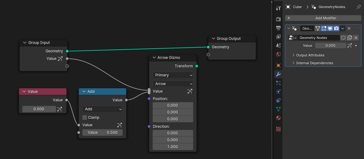
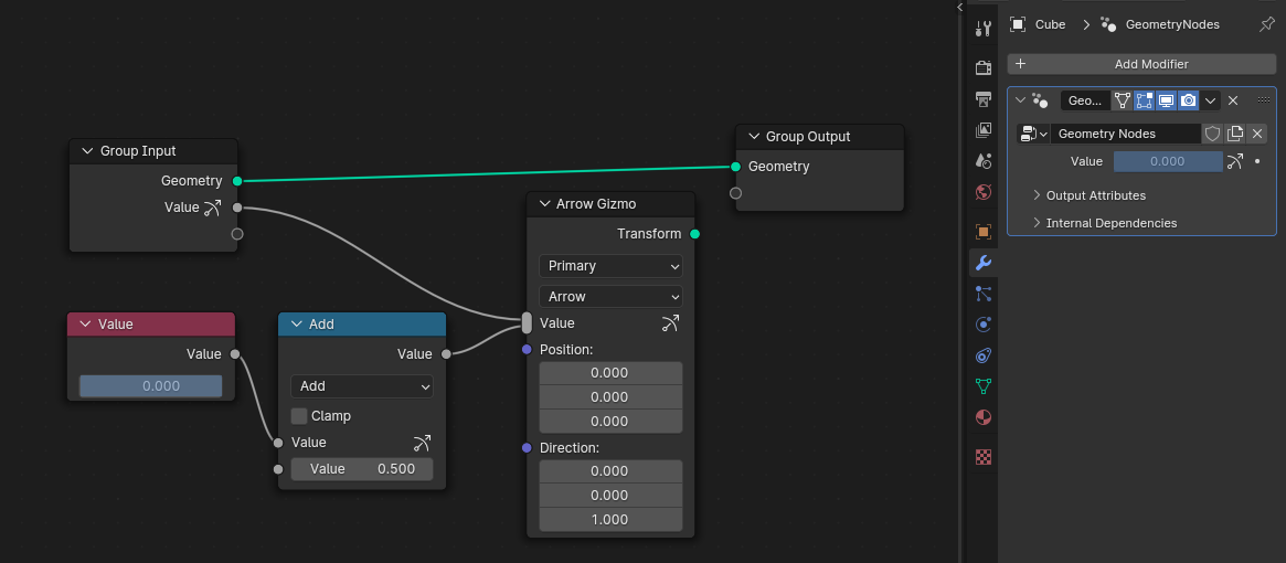
- Experimented with a new UI for showing which values have gizmos attached. Nothing is final here.
For example when rotating the geometry with a Set Position node with some custom math. The limitations are generally similar to curves sculpting on procedurally transformed curves.
That’s certainly an issue. Seems like something we won’t have initially but might add later when it becomes an actual problem.
Something that is driven procedurally can’t be modified by a gizmo. The gizmo essentially just disappears (unless it can automatically figure out how to attach itself to the value that is now driving the input, which is used quite a lot, e.g. when using a multiply node to change the gizmo-to-value mapping).
It only works for functions that have inverse (or a function that is almost an inverse). Blender doesn’t know about the inverse of many math functions currently that could have one in theory. I’m still working on the visualization. This update makes it a bit more obvious when a mode breaks the gizmo backpropagation because the gizmo icon on the input socket disappears.
It’s a fundamental requirement of the design. Rerouting nodes back in the opposite direction would not solve it.
Seems like something that might be added eventually, but probably not initially.
I think we can make auto keyframing work here, but I’m not entirely sure how that works yet. Haven’t looked into how that is implemented yet. Might not be part of the initial version.
That does not feel like a scalable solution when many nodes in a node group have gizmos, so probably won’t exist initially. Seems more likely that we’ll have some kind of pinning functionality eventually where a gizmo stays visible even if the corresponding node is deselected.
8 Likes
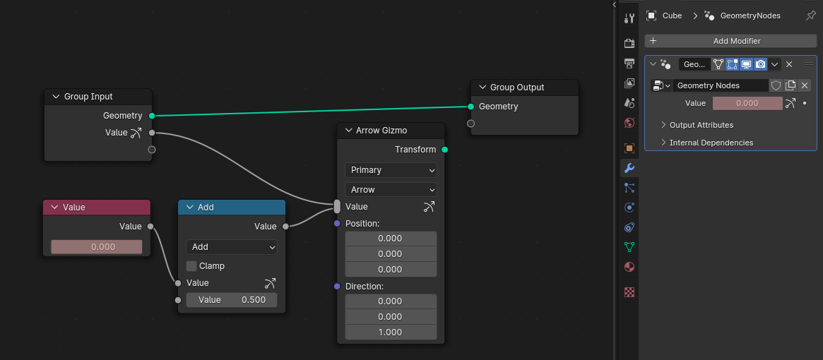
I like the icon, especially in modifiers tab, very clear, and I like the choice of icon very much too. But they don’t look good in node editor properties imo, and I still think coloring of the property is still needed. I think it will break consistency in Blender if its not colored, since every time that property is driven or used in some way now we have some color for it, and this will be an exception. And color will make it more visible too, at first glance you’ll know what you can change in 3D viewport. But something subtle and not as pronounced as driver & keyframe colors.
Colored properties in node editor instead of icons, and colored property alongside icon in modifier will work best I think
2 Likes
A potential problem with using colored properties is that the properties can have keyframes AND have a gizmo attached. Any idea for how could be represented?
Hmm good point. Any way to address that issue will overcomplicate things for sure. So either it can be without color, or it can have color until it’s keyframed or driven. I like second choice better, it still gives more information out of the two, and I think if somebody keyframed gizmo positions they already know which properties they’re working with and don’t need that identifier anymore anyway.
And that idea took me down another path and tried attaching driver to the value that is being controlled by gizmo. And as was probably expected gizmo doesn’t work anymore, it can’t change anything, but is still there and its position is updated.
I think there needs to be some UX there too, maybe make gizmo disappear, and turn gizmo icon in modifier into info/error icon that popup on the nodes when you plug in wrong type of geometry, so that it tells you gizmo is not functional anymore.
I am still trying to figure out the technical limitation that doesn’t allow value to be output, but has to be input instead. I mean gizmos are essentially just some objects in 3D space with location and direction.
Naively, the abstract way I would expect them to work is that their inputs would be initial position and initial direction vectors, and their outputs would be current position and current direction vectors. So user could then take these 4 values and use them to drive anything they want. For example use distance from initial location to current location to drive some value, or use dot product from initial direction to current direction to drive something.
All these examples show very simple scenario, but I am just worried about quite overcomplicated node networks if there are many more nodes between the gizmo value input and the value constant.
So basically the input values of the gizmo would be where it’s initially supposed to be positioned, and output values would be where the gizmo currently is (after user has transformed it in the viewport). That would feel more intuitive than the current bidirectional feedback loop setup user is required to make.
So that was the reason for my original question - if the reason of the gizmo output being on the input side was aesthetics/convenience or some technical roadblock that wasn’t solvable any other way.
That icon placement and appearance just looks… sort of hacky and arbitrary.
Perhaps something that looks more directional, and like everything else.
4 Likes
It is possible to have two gizmos on a single value.
Is there a use of multiple gizmos on one value?
They mentioned an example use case in the proposal
This approach allows the same input node to be used with multiple gizmo nodes. I could see this being useful in more complex setups like a castle generator where there are multiple gizmos in different places that control the same wall thickness.
Thank you.
I think I get the idea now. In a more complex modifier, being able to tweak the same value from different locations (instead of sniping for a gizmo somewhere).
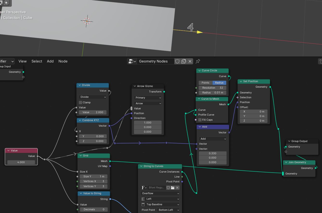
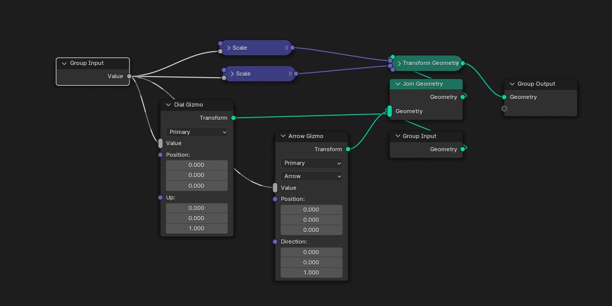
The problem with this node-tree is that the Gizmo value ignores the math node, and jumps directly to affect the output of the “Value” node instead, therefore connecting it this way makes little sense.
Maybe a good idea is to separate the Gizmo node into two: “Gizmo value” and “Gizmo Display/Shape”.
These two nodes would need either a name or an index number to be linked together.
Perhaps easier with indexes.
So… the “Gizmo value” node would have two inputs (“Index” (integer) and “Type” (Float, integer, etc) and one output: The “Value” output would simply be based on the “Type”.
The “Gizmo display” node would look exactly like the Gizmo node is now, except that it wouldn’t have the “Value” bidirectional input/output socket, and would need an index integer value input.
If “Gizmo value” and “Gizmo Display” have the same index nr, they are linked. Adjusting the displayed gizmo adjusts the value and visa versa.
The only problem that remains is that there is no way to connect a gizmo to the primary node-group input with a line.
That can be solved, if there is a new setting in the “N” panel, for node-group inputs, which is simply called “Gizmo index”. The user would just write in the gizmo index number, and the input would get linked to it.
If a node group input is linked to a Gizmo in this way, there is no need to use the “Gizmo value” node anymore.
NOTE: The Gizmo indexes would be Groupnode dependent. A Gizmo with an index of “1” is not the same Gizmo, with the same index, outside of that nodegroup.
This is quite more complicated than the current design, but this makes more sense to me.
Also, this design would allow two gizmos (or more) on the same value, as @LeonardSiebeneicher requested. To achieve that, the two “Gizmo Display” nodes would just need the same index number.
The best solution i could think for that is having a new button icon on the header of the modifier, along with these:
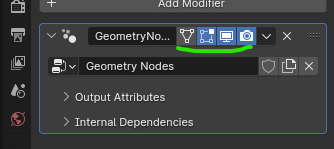
The new icon would have three stages: “Always display gizmos”, “Display only when modifier is active” and “Don’t display gizmos”.
Gizmos are a visual way of editing the parameters of geometry nodes and modifiers. Similar to how transform gizmos are a visual way of editing the location/rotation/scale of an object. Not like an additional object that is driving the object transform.
You want to be able to inspect, manually edit and keyframe the resulting parameters on the modifier.
1 Like