No, not independently. They’re snapped as a whole, unfortunately, even when using individual origins. However there might be a better way to do what you want to do ?
for this type of thing I just use a custom operator to quantize geometry on-demand. it doesn’t really make sense to snap individual elements en masse while doing a transformation, because if everything is already on the grid, everything will still be on the grid if you’re transforming while snapping. It’s far more frequent that you find an element that has been bumped slightly out of position and a quantization operator will move all verts to their nearest grid position.
4 Likes
That’s the problem exactly. Since snapping is currently averaged between the selection it makes it way to easy to bump individual vertices out of position. It’s one of those errors that occurs quietly and can drag through unnoticed way too easy.
2 Likes
When modeling architectural objects, you often have to tie railings to walls and columns. Snap in the closest mode is not always obvious (when pulling at the bottom of a wall or column). . Instead of the expected snapping on the outer side face, the snapping of the nearest elements occurs. This is very inconvenient - you have to switch to the active element mode and then back.
Is there anything you can do about it?
Maybe some kind of checkbox “closest to cursor” or “closest boundary” mode.
10 Likes
Indeed, when you work with flat architectural plans and 3d geometry (2D to 3D case) it is quite annoying - for example, legs of furniture is always in higher priority than actual boundary and so one.
In 3D to 3D case, snap result depends from geometry and cursor position simultaneously, so it is hard to get predictable boundary result when it is needed.
Both cases are useful, so I think it would be nice to have such an option
1 Like
I believe, if this topic
was solved its gonna help a lot in this discussion.
This was topic where users massively confused blender origin and maya/max pivot point - a systems that look the same (a point with arrows) but behave different - so they tried to bring to blender incompatible industry standard behavior that messes up with instances (linked data objects), bringing a chance to corrupt the entire scene.
no no no, that’s non sense. no one confused anything
you are just afraid of improvements, like many hardcore blender users around here
and because of the crying noise you guys make, many great features are not implemented
you guys really should think twice before jumping into a conversation about industry standard features
you’re just blocking blender’s evolution with this weird line of thinking
2 Likes
Systems are software independent.
In industry standards two ways to handle object centres are presented.
They are
- the Origin system (Blender origin, AutoCAD insertion point, etc) - object center represents a true mesh origin and affects instances.
- and the Pivot system (3dsmax pivot, Maya pivot, c4d pivot, etc) - object center represents a dummy that doesnot represent true mesh origin, so it does not affect instances.
They look the same (a point with axis) but behave differently, so systems are different and the applicable set of features is different as well.
The problem is that lots of users that learned a single software are confusing those systems, since they look similar.
7 Likes
so, making easy to edit pivot, in edit mode its a bad idea ?
just read the article to get my point.
just forget about maya max autocad etc…
its about making thing faster that I care.
snapping like I said its gonna solve a lot of problems if they add feature to affect pivot point in edit mode.
As far as I remember, modo is the only system where both pivot point and origin systems are presented explicitly.
To edit pivot point in edit mode you need to add pivot point paradigm to Blender first. As it was discussed, it will at least clone 3dcursor/active element functionality.
It will be something like a 3dcursor with arrows with the ability to move it with selection, which will be quite complex-to-handle system, especially if to take into account that the goal of such a system is basically to solve basepoint snapping.
2 Likes
ok so I guess its the core in blender and can’t change.
if they manage to let 3Dcursore act more like pivot actually its not gonna be bad. its still I need to figure out how to minimize the click.
1 Like
Well, there are several ways to handle transformation center.
- center is separate and geometry dependent (3dsmax pivot, Maya pivot, Blender Active element)
- center is separate and geometry independent (Blender 3d cursor, 3dsmax Working pivot)
- center is tool-centric and is set by tool each time it is invoked (CAD systems, for example CAD-like basepoint transforms)
All of them has they pros and cons taking into account conditions, realizations and so one.
Hey Paul!
Your last couple posts on this topic is very enlightening. I think I’m one of those people who came from a Maya, 3DS Max, C4D (Modo a long time ago but forgot that it has both) and confused the pivot point with the object origin. I was startled to find out that blender can transform objects around pivot points during object mode when I was fiddling with stuff earlier today…
You got me thinking more about it, and I’m curious:
- Could you further illustrate the difference between pivot points and origins?
- How adding the ability to adjust a pivot point would be complex to design? (Couldn’t it just follow wherever the transformation handle is move on initial selection, and then be moved from there in a separate mode? If not locked that is)
- How would adding a dynamic pivot point would be basically solving basepoint snapping?
Thanks a bunch!
Hi.
I made several preparation to the questions like that, but currently I am ready to answer just the first one due to high workload. So I will answer it first.
- How to illustrate the difference between pivot and origin systems?
The difference is in mesh influence, so we can spot the difference by creating instances (called linked data objects in Blender) and checking how origin/piviot grabbing influence them.
Here is an example from 3dsmax (I do not propose anything from this gif, so I guess I can use it here to depict how pivot systems naturally works)
I created several instances that share the same mesh, and tweaked their pivots. It is possible to put all the pivots to a single 3dspace point, but object Meshes will kept their positions since pivot doesn’t influence mesh.
Pivot system behaves like that (instances can have different pivot positions):
If you will try to recreate this case by making several instances in Blender (via alt+D) and will try to grab origin (via Ctrl+. shortcut), grabbing origin of a single element will change the position of its instances, since origin influence mesh.
Origin system behaves like that (instances can’t have different origin positions):
The trick is that 3dsmax has both pivot and origin systems that allow to create and keep instances the same way at the system level, but the origin system it is not originally exposed to the user there.
That means - you just disallowed to view true mesh origin properly in 3dsmax (and Maya), so most users don’t have a clue about origin system when learn this software.
However, if you will export those instances from 3dsmax to Blender via FBX (which is a 3d file format that keep instances), you will see true origins of meshes instead of pivot points, since origin positions will be different from pivot positions you originally set in 3dsmax.
The inability to detect true mesh origins in 3dsmax cause quite heavy problems there, for example your pivot can be close to mesh geometry position, so you are supposed to think that everything is ok, but true mesh origin can be kilometers away, in that case your mesh will be laggy with no visible reason.
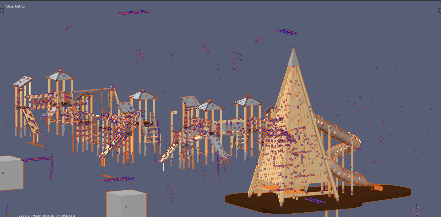
That is also the reason why all mesh origins are usually so randomly spread across 3dspace when you import 3dsmax models to Blender - the problem is the same - you don’t have direct access to the origin and object+mesh data systems in 3dsmax to control them properly, so even if your pivot points are accurately organized, imported origins almost always looks like that:
It is a complex and deep topic about software system design, I hope my explanations sounds clear.
9 Likes
Wow, Paul!
Thanks so much. That is such a clear explanation and really helps me understand the difference.
When you have time, I’d love your thoughts on what it would look like for us to implement a pivot system in blender, where objects, object / collection instances etc. have stored pivots (and could store multiple pivots that could be enabled and disabled). Would this be something you could see being developed and added into Blender as it currently stands? Or would it require a rework of the existing transform system?
Speaking of which I’ve also heard people reference that before (a transform rewrite) and I’m not sure why people think the existing system requires that. Do you know?
And if you really want to go wild, what would a new / rewritten transform system look like for you ideally? From what I’ve seen of your work it had a lot of precision and requires a number of CAD like functionality that doesn’t seem to exist in Blender currently. I wonder how that could inform that new / reworked system?
I am really loving Blender and while I have other projects currently that I’m working on for the core (the asset browser and grouping) I’d like to at least start getting together an ideal shot of what an ideal transform system looks like, so that I may help in that development when it comes time.
Thanks so much!!!
1 Like
As you can see, the key difference between those systems is very unobvious and is quite hard to discover, especially if to take into account that the essential part of an engine is just hidden from user in industry standard software - you have to be familiar at least with instancing and its exports issues. It is easily possible to use software for years and dont have a full picture in mind (it also took a lot of time to me before I decided to investigate how those systems actually works instead of just keeping using them)
Technically, lots of different software solutions are just full of that kind of “hidden mines”.
It is also quite a depictive case when you need to learn something like Blender or Modo in order to understand what is goin on under the hood in something like 3dsmax or Maya.
2 Likes
Having read the last ~100 posts, the conclusion that the design is stuck on keymaps is quite disappointing. My take on this is very simple (from a user’s perspective). Taking these three into account:
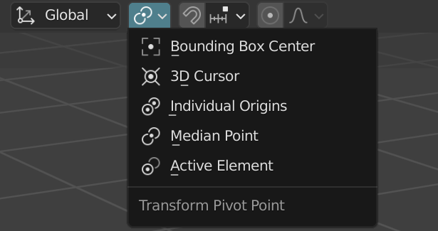
I think that Blender should build upon #3 tool centric origins, because it is the most flexible. I would propose a persistent mode for ‘Pick Transform Origin Point’ that should reside in this menu:
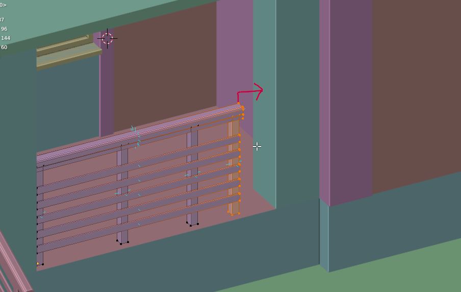
Each time a transform is invoked (i.e. scale, move, rotate) the first click is to set a temporary origin from which the transform executes. For instance with the fence example
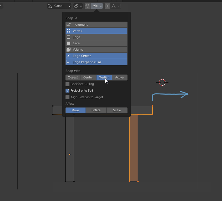
You would
- pick the point that should snap to the wall as origin, the top right vertex
- enable constraints on the X axis and
- snap to any point on the wall (right hand line).
The way I see it is that this option should be a checkbox to enable. The discussion should then be on which tool would benefit from this. Thanks to the checkbox, you could use “Median Point” as the default origin, but any tool that supports the ‘Pick Transform Origin Point’ would use this mode instead. Hotkey ‘Pick Transform Origin Point’ to F8 or so to enable/ disable the checkbox (if anything it could be left blank and let the user decide). So each subsequent transform would default to ‘Pick Transform Origin Point’ if enabled.
1 Like
The problem of such solution is that it is heavily CAD-related. It is ok to use such design in limited range (like drawing/drafting programs, suitable, for example, for architecture) , but it doesnot fit wide-range systems well.
In wide-range systems, which is supposed to be used for a wide range modeling - from organic characters to precise architecture, where action starts from freehand operation, and the amount of CADness of an operation is defined by the amount of restrictions per operation, quick behaviour alternating is important.
With proposed approach (we call it a CAD mode) to alternate different behaviours you will be forced to switch such checkbox on every single action.
None of what you said makes sense, there is no such thing as CAD only or CAD related, you are the one associating a sequence of commands with CAD. Alias is rather different from Autocad (single button shortcuts vs command line) both are CAD software.
This is about the best solution for a given problem. Not about blocking a proposal for a perceived problem that is non-existent (‘heavily CAD-related’…).
Both a two click move as modal, or a persistant mode require the user to toggle the key every once in a while. Depending on the workflow one is more laborious than the other. Additional pivots is just the same thing, but then they need to be moved in place and such. A working pivot for this workflow, as you seem to suggest, is not the best solution simply because a polymodeler (3ds Max) uses this.