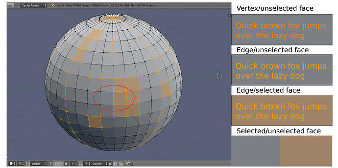
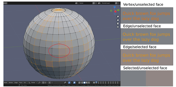
I think it very important after years of pushing such a design.
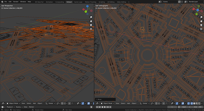
I totally agree, especially when sculpting this is a massive problem because of the very dense meshes.
In my opinion the 2 ways of fixing it which also can be combined are:
- Decreasing edge line width
- Decreasing edge line transparency
Next issue: flat surface coplanar faces topology display/detection.
Workflow: Any, for example concepting, working with imported geometry, etc
The task of making the third cylinder looking similar to the second is to visually determine its true shape.
Third one has triangulated mesh, second one is not triangulated.
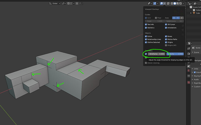
A triangulated cylinder in Blender 3.0 show triangulation of a flat surface, it is impossible to bring its appearance to a true shape, edges on a flat surface do not behave like they belong to a flat surface.
Even edge split modifier hint (which is not suitable for lots of imported geometry anyway) does not bring proper result.
Yep, I talked about this problem in blender chat and after some words developers saw that the problem was the fresnel and promise the patch for blender 3.0 to make optional. With that the 90% of wireframe problem must to be gone.
How long has it been?
Also, what do you think about such a suggestion?
https://developer.blender.org/T90641#1205974
Since january or february
Gorgeous. Thank you!
Yeap, I really miss a way to hide all coplanar edges in object mode. (it used to work in 2.79).
Now even with wireframe slider set to zero, not all coplanar wires get hidden. (yes, face normals are all outside)
Yes, we are using 2.79 because of wireframe issues like that, since it is essential to detect coplanar faces during CAD modeling (especially for manufacturing), and such an appearance makes reading geometry incredibly hard, triggering modeler to fix lots of displayed but unexisting model issues, since they are recognisable as a mesh tearings.
About model issues.
I like that you reported about face normals, because we can’t see them instantly on your screenshot.
Face normals detection was disabled by default in the most industry standard software, so every single time you have to check it manually, even if it is an important part of information about model structure.
Of course, if user have no ability to see a problem, he will never check for a problem, so nobody makes that untill some bad things happens.
As a result, flipped normals is an industry standard meme, which lasts for last 20 years - there is even a popular CG youtube channel called Flipped Normals, named after the most recognisable mesh modeling error.
When we was using 3dsmax and Maya we got flipped normals from every modeller and outsource freelancer we was working with, so companies like our have to punish them in order to make them a motivation to properly check normals.
When we switched to Blender the issue has gone - face normals was easily detectable by default, but it was brought into Blender during 2.8 redesign with explanation like “in some cases detecting normals is not needed”.
I don’t know how it was possible to not to know about such a widespread design mistake, which is a meme for all this time, but it seems that by design it is supposed that we should again massively punish every modeller we are working with, just like when we was using 3dsmax.
I never use this slider. And I can`t understand why it works as 0—1 dloat instead 0—180° despite it is actually use degrees?
Slider concept is actually helpful for proper model presentation for the cases when it is needed (for example, in architectural concepting - to present neat looking model to a client, or in landscape design - to detect cliffs, etc), even if it is not used most of time.
But yes, it is limited to 0-90 degrees and displayes 0-1 scale, which is a limitation in my opinion as well.
0-180 degrees scale (like Autosmooth has) seems to be a more pecise and profitable solution in a way:
0 - all edges are visible
1 - coplanar edges are invisible
180 - all edges are invisible
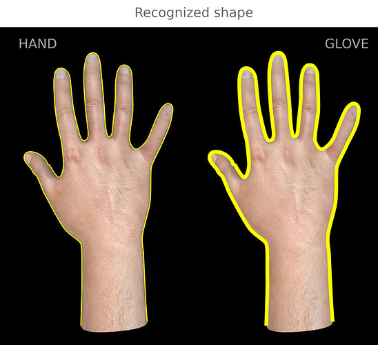
Outline is still unusable.
It is animator’s setup massively pushed to everyone, including modellers, so they can’t detect structural order properly.
For modeling:
- In shaded mode you detect object’s surrounding and its order.
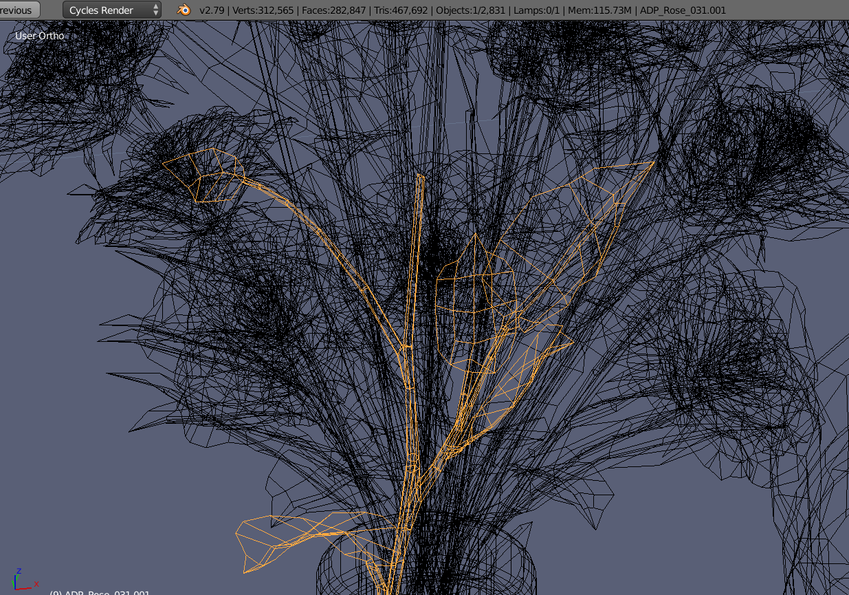
- In wireframe mode you can detect object’s structure and shape.
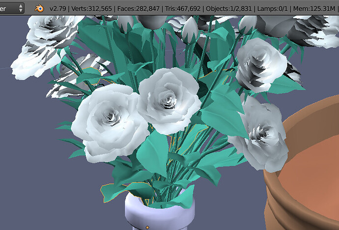
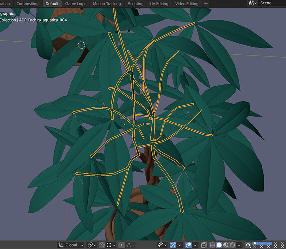
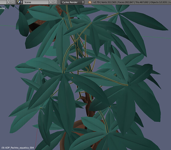
Here I can clearly see the order of the selected object:
Here I can clearly see its structure in 3d space if it is needed:
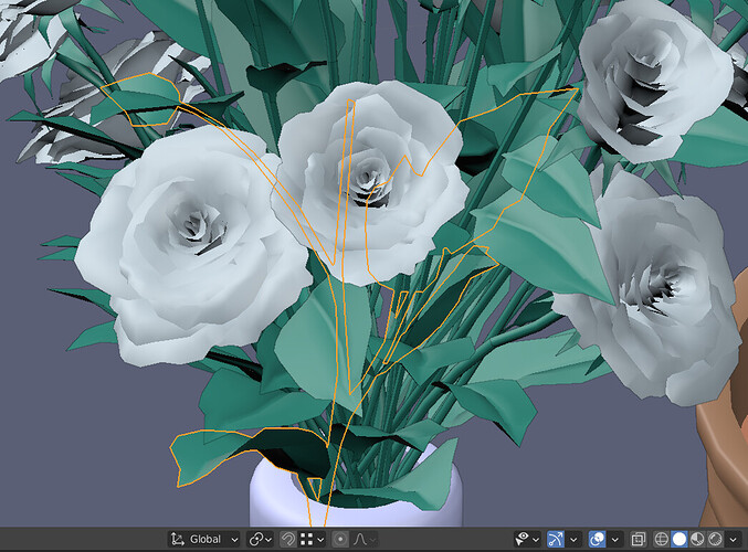
How we supposed to read a true order of this mess, it highlights through everything as a flat contour, like in Unreal, which is not supposed to be used as a modeling software, just for pasting ready-made assets:
Which leaves cover the selected twig?
The right answer - here they are:
As far as I understand, such a design was taken from 3dsmax, but in 3dsmax it is provided the ability to disable it for complex and precise modeling purposes, where the ability to confidently perceive the order of objects is essential - which was part of a balanced design that takes into account both modeling and animation workflows, which you can choose according to demands.
This is why it is not advisable to clone the features or visual appearance of other software without understanding the deep context behind it.
I think it’s because by clicking in same position in 3d view you can select object located inside other object (is it also presented in 2.79?). And only way to see it - make overlay globally.
But I agree the option for highlight only visible contour of an object - must have.
Yes, both representations have their own mutually exclusive but clearly defined workflow-dependent usecases.
That’s why in 3dsmax both options are presented.
Here we got a half of an original system presented in 3dsmax just because it was a half presented by default.
The same problem has Linux when tries to clone visual appearance of Windows UI ignoring the implied functionality, which leads to heavy UX problems.
It is impossible to make a nice and useful for a wide range software cloning only default appearance of a systems presented in other softwares - it leads to a workflow limitations which results as a scope limitations.
Next issue: Fresnel effect in wireframe shading mode makes mesh drawings hard to read.
Workflow: Architectural/multiref modeling.
Wireframe fresnel effect makes drawing references hard to read, since it make them look different and dims them at different view angles. Shimmering drawings are incredibly hard to percept.
Side-to-side brightness comparison
lots of good points here! I guess this also has to do with the fact that wireframes thickness remains the same no matter the zoom distance. When you zoom out the wires get clogged.
I has got an idea to depict lower selection readability by comparing to text readability.
Same matcap, same mesh selection, color samples are taken from zone marked as red:
2.7 - text colored in viewport selection colors is readable at least at the minimum comfort limit. It is still pretty quickly perceptible and recognisable.
2.8+: the readability of text colored in the viewport selection colors is straightly below the minimum comfort level due to color darkening by the Fresnel effect. Vertices, edges and faces selection is physically much harder to recognise, so you have to search your selection on your screen instead of immediate perception of it.
Since mesh selecting and selection control is the most relevant mesh modelling operation, such color scheme and mesh selection effects cause a heavy usability problem, especially during working with image refrences infront overlays which dims the selection even more.
