Post BCON22 Workshop
This workshop happened during October 31 to November 3, 2022 at the Blender head quarters in Amsterdam.
Attendants:
- Dalai Felinto
- Hans Goudey
- Jacques Lucke
- Simon Thommes
Agenda
- Spreadsheet Editing
- Import Nodes
- Procedural Hair Workflows
- Attribute Editing
- Dynamic Socket Type
- Dynamic Socket Count
- Simulation
- Automatic Caching
- Freeze Caching
- Geometry Object
- Usability
- Node UI
- Math Nodes
- Preview Node
- Menu Switch / Enum
- Comments
- Loops
Spreadsheet Editing
- Selection
- Only in modes that visualize the selection in the viewport (edit mode, weight paint, etc.)
- Sync selection with viewport
- Selection is displayed as a color
- Active
- Display the active element with the active color
- Data
- Editable in all modes
- Easy to tell what original means if you can always edit it
- Display
- In original mode, display derived data grayed out (normals, more in the future)
Import Nodes
- String socket file path subtype
- Alembic
- File string input
- (Optional) object path
- Frame input
- Geometry output
- New instance type (Alembic instance)
- Validate meshes
- OBJ
- Validate meshes input
- STL
- USD
- More options
- CSV
- Creates a point clouds
- Also creates an instance because…
Procedural Hair Workflows
- Two basic questions
- What new building blocks are needed to build the high level groups?
- What high level group do we use to replace the building block?
- Guide curve workflow
- Like children in the particle system
- Technically possible in the current system but very limited
- Interpolating positions is possible, but affecting all attributes is impossible currently.
- The density brush is similar to the children creation
- Sample curve node (already finished)
- “Ignore self” in proximity sampling
- Needed generally but also sounds useful here
- Something like “Use 2nd closest point”
- UVs and surface object should be more easily accessible
- High level groups
- Clump
- Scatter/Children
- Frizz
- Curl
- Group index idea is important for interpolation
- Parting and clumping should be index/id based
- Distribution on the undeformed source mesh
- Accessing the original geometry may be important
- The rest positition attribute gives more control
- Creation of curves inside a “tube” mesh
- The algorithm isn’t clear yet
- The topology would be a tube but the deformation could be arbitrary
- Maybe the ring index could be an attribute to make the topology clearer
Attribute Editing
- Mesh, curves, and point clouds
- Edit mode
- Use case is as an input for procedural generators
- Miscellaneous features like randomize attributes, etc.
- Operators act on the active attribute
- All attributes are displayed for the active element in the viewport sidebar “Attributes” panel
- For multiple selection
- The buttons/sliders “offset” the mean value
- Operator to set all selected elements to a value (prefilled with active value)
- Attribute overlay for active attribute
- Drawing edge attributes
- Thick wireframe drawing like seams, bevel weights, etc.
- Drawing edge attributes
- Gizmos to edit original data (for later)
- Checkboxes for booleans
- For vectors: directions, offsets, etc.
- Rotation gizmos
- Connects to the node tools project a bit
- Attribute paint modes
- Artistic paint mode
- Supports meshes
- Point and corner domain and color types and float attributes/textures
- Sculpt color implementation should apply to any attribute type (within reason)
- Technical paint mode
- Supports meshes, curves, points
- Supports any domain and any type with special tools for some types, also supports textures
- In between edit mode and the more artistic painting currently in sculpt mode
- Choose a value of any type and paint it directly
- More advanced painting
- Flow maps
- Face set interaction like sculpt mode
- An option on the attribute chooses whether it shows in the more artistic mode
- Paint canvas
- Texture canvas
- Choose between a list of all textures associated with an object
- The canvas can be sourced from (1) material + layer stacks; (2) modifiers; (3) attributes
- The source is used for filtering and visual clues
- Embrace syncing the active texture between the node editor and the paint modes
- Make setting the active texture canvas active an explicit action
- UV is set per layer stack, or sourced automatically from the node texture
- Multi-object texturing
- Painting on the same texture across multiple objects
- Bleeding should be smart about other users of the same texture
- Choose between a list of all textures associated with an object
- Artistic paint mode
Dynamic Socket Type
- Initial type is “Unassigned”, no values are shown for the dynamic sockets.
- Dynamic sockets can be chained, preserving its unassigned type.
- The first time a type is connected to a socket, the type is set for good
- To set it to a different type go to node options or context menu
- To reset to Unassigned, first disconnect the sockets then go to node options or context menu
- Don’t show the type option in the node by default
- Have it in the node options
- Optionally also in the context menu
- Dynamic sockets are ignored in the modifier UI
- It needs a design for how it looks when unassigned (e.g. rainbow)
- When assigned they look like regular sockets and maybe when assigned (so users know they are dynamic)
Dynamic Socket Count
- Designed to allow encapsulation of complex behavior in a flexible way
- Sockets are grouped together in clusters
- The last entry in the cluster is like the group input/output sockets and makes a new connection
- “Udon” noodles pass multiple sockets at the same time
- It’s basically a list of sockets of different types
- Udons can be exposed to the group output as one of the inputs to the cluster
- Corresponding inputs and outputs are aligned
- Builtin nodes like capture, sampling, raycast, etc.
- For group nodes, the alignment would happen whenever Blender can figure out that the mapping is clear
- Join node
- Joining attributes currently requires the hack of adding them later
- Option 1
- Cluster socket of multi-input sockets
- Requires ugliness for matching the order between multi-input sockets
- Option 2
- Cluster of clusters that each contain the same socket types
- Option 3
- Join in a separate node
- Currently unresolved
- Multi-input socket
- Technically redundant now, though more elegant on a UI level
- The join node might have to move away from multi-input sockets
Simulation
- Physics vs. simulation
- Simulation is mostly about retrieving data from the previous frame
- Physics is a subset of simulation, with specific solvers for physical phenonema
- Global vs. local
- Local is a single object
- If we start with a local case, it should extend to the global case without completely changing the design
- Local simulation design
- Simulation input and output nodes
- People do so much with the currently available tools that just giving access to the previous frame’s data would make so much possible
- The design could be similar to the repeat loop design, but we need nested loops, not necessarily nested simulations.
- Simulation input and output nodes control the simulation
- Restricting simulation input and outputs
- There is no reason to restrict inputs
- For inputs that are only evaluated on the first frame, the simulation input node is used.
- Outputs can only be connected through the simulation output, for improving the subframe workflow
- Time
- Simulation input node has an output for the time delta since the last evaluation
- Scene time
- Time of the animation system, tied to the scene
- Simulation time
- For the interactive mode, separate from the scene time
- Specific per object
- If you only need the delta, the absolute value isn’t necessary
- Simulation input node
- Inputs
- All inputs are evaluated only once at the start of the simulation
- “Run” (True by default)
- Outputs
- All inputs but “Run”
- Delta Simulation Time
- Elapsed Simulation Time
- Inputs
- Simulation output node
- Inputs
- All inputs but “Run”
- A “Stop” value that breaks the simulation until the simulation clock is restarted
- Output
- All inputs but “Run”
- “Simulation started”
- “Simulation ended”
- Elapsed Simulation time
- Inputs
- Run and stop
- The simulation still caches the final step on which the stop was set
- The simulation always pass the final cached step
* When the “Run” hasn’t been on yet, the simulation pass the input data through - When the “Stop” is on, the simulation pass the final cached step
- Cache
- We cache on modifier similar to existing physics systems
- We may version it to move the cache to a simulation datablock later
- The caching itself (its data format) will focus on performance
- It may even use .blend files for that
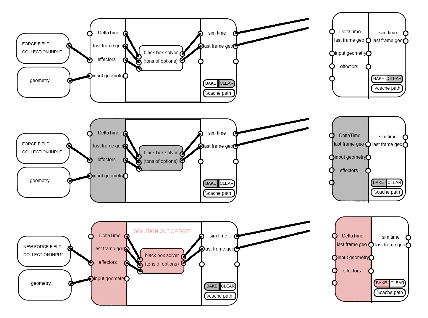
- Because subframe mixing requires mixing between cached frames, it is impossible to pass links directly out of the simulation without connecting to the simulation output node.
- Frame UI
- The goal is to make it clear that links cannot pass out of the simulation, but they can pass in.
- All simulation nodes go inside of a frame
- On each side of the frame there are sliding input/output nodes with the simulation state sockets

Automatic Caching
- Anonymous attributes
- Outputs can’t depend on whether other outputs are needed
- Higher level way of determining when anonymous attributes should be propagated
- Anonymous attribute names derived from the compute context
- Force the deletion of anonymous attributes when leaving geometry nodes
- Heuristic for what to cache
- One idea is that each thread would cache arbitrary data after a certain amount of time passed
- A simpler node-based idea is to cache a node’s output when it took a certain amount of time
- Finding a good heuristic will require more testing
- Detecting changed inputs
- Compute a “proxy value” for each input, which is like a hash. Generally they shouldn’t change when the data has changed, but it’s okay when they do.
- Propagate the proxy values through the node tree, mixing them together to determine when they changed from the cached value
- Next steps
- Anonymous attribute static analysis, making anonymous attribute handing more functional
Freeze Caching
- Also requires anonymous attribute static analysis for improved usability
- Without the “edit mode node” functionality, the feature is relatively simple
- When geometry is frozen, it is saved in the file by the modifier
- Requires saving and loading non-main meshes
- Anonymous attribute handling
- The node tree automatically freezes fields used with the frozen geometry as necessary
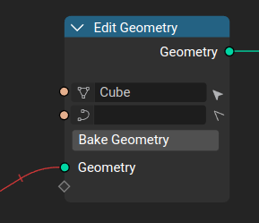
- Those fields are automatically populated in the checkpoint node and connected to their original nodes
- The node has datablock slots for the different domains
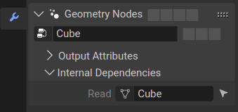
- The datablocks inside a nodetree are exposed in the modifier “Internal Depedencies” list
- This node is used for the primitive objects (e.g., Cube)
Geometry Object
- Related to Freeze Caching
- All the geometry-related types are unified as a " Geometry" type
- In the object panel there is a list of geometry slots
- The list is read-only, based on the node-trees
- Only one geometry can be active, and this is used to determine the available modes and panels (e.g., UV)

Usability
- Gesture operator to create capture attribute node like the mute or cut operators
- If a geometry link is included, it is used, otherwise there is no geometry connected
- In the toolbar and possibly as a shortcut
- Field connection visualization
- While dragging a field, differentiate sockets that lead to an evaluation in a non-compatible context (don’t contain all necessary attributes)
- Graying out sockets and links is preferrable over highlighting since many sockets would be highlighted
- Field evaluation context inspection/visualization
- In tooltips for field sockets, show information for evaluation contexts
- Domain and the kind of context
- Field input warnings
- Vizualizing the context
- Visualize the nodes that the field is evaluated in (and optionally the geometry socket)
- Visualize the path to those nodes and sockets
- Triggered explicitly by an operator or socket selection or delayed on a hover
- Possibly toggled as an overlay option
- Visualizing evaluation on sample nodes
- Node panels can give a visual suggestion for many nodes
- Organized in the node group sockets list as a tree
- No header or dropdown in many cases, just a common background color or separate to group related sockets
- Node panels can give a visual suggestion for many nodes
- In tooltips for field sockets, show information for evaluation contexts
- Interpolate domain naming
- It sounds like it’s interpolating to the domain that’s selected but that’s not what it’s doing
- It used to be called “Field on Domain” which was clearer. “Evaluate on Domain” is better.
- Add menu
- Just start typing to open the search
- Add multiple ways to access nodes with different properties in search
- The add menu should use submenus more
- Focus on searching
Node UI
- Subpanels
- Rational is keeping direct/immersive interaction but providing better grouping and hiding away unnecessary sockets
- The idea is to give users the framework Blender uses, with constraints if needed
- Subpanels can be used for outputs and inputs
- By default they can be expanded or collapsed
- Subpanels are organized by a tree view in the sidebar
- If a subpanel is closed but a socket is linked, it is still displayed but with no text
- We need to collect use cases to map out the final solution
- Hiding sockets
- Rational is clearing up the UI to the point where you have exactly the parameters exposed that you want to control
- When every socket in a panel is hidden, the panel is hidden as well
- Add a bar to the bottom of sockets to roll/unroll the node
Math Nodes
- Split up the math node a bit. The ideal segmentation is arbitrary.
- We don’t want to use a node per operation because that makes switching more complicated, but the current math node has too many responsibilities.
- Math node
- Does generic math operations
- Uses dynamic types
- Vector math
- Only does operations that make sense on vectors
- Compare node
- Dynamic type, generic or type-specific comparison operations
- Needs more discussion
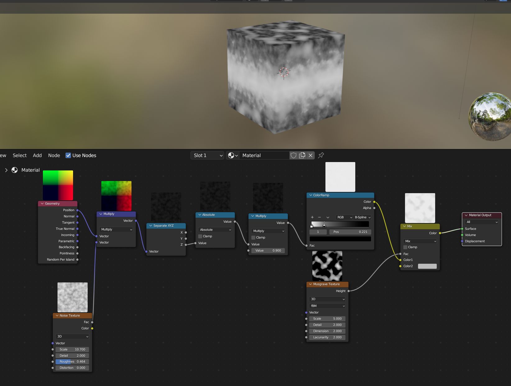
Preview Node
- Currently the evaluator always calculates the output even if it isn’t visible in the UI
- The depsgraph doesn’t know about the UI currently, but it should be able to skip evaluation when the result isn’t visible
- Take UI visibility into account for the depsgraph
- A more manual solution is “pausing” evaluation, which is related to cancelling
- A patch currently works on Linux, but the Blender needs to be okay when the evaluated state doesn’t match the expectation
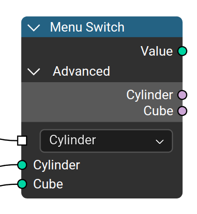
Menu Switch / Enum
- Requires dynamic socket type
- Design focuses on an “Menu Switch” node which is used to define the enum options in the sample place it switches
- Has an enum selector and inputs for each option where the names are defined
- Adding another enum is part of the node, it is not an udon
- Sockets are called “Menu sockets”
- To add and name the sockets users go to the node options
Comments
- Comment node
- Options for transparency
- Edit the text directly in the node editor
- It might be helpful to attach it to nodes
- Resizable in all directions
Loops
-
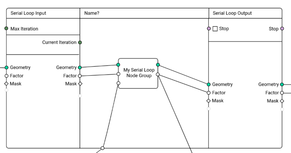
Serial Loops (Repeat Loops)
- Very similar to the simulation design
- Max iteration count input, current iteration is passed to the inside
- “Stop” output on the inside to allow stopping iteration early, also outputted to the outside.
- Debug iteration index in the UI for socket inspection and viewer nodes
- It may make sense to add a switch to disable logging completely
-
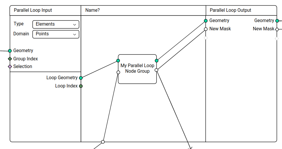
Parallel Loops
- Very similar to the serial loop
- Two modes: count; elements
- Count:
- Input Input: Count
- Input Output: Index
- Output Input/Output: Geometry
- Elements:
- The geometry is separated into groups
- Option: Domain
- Input Input:
- Geometry
- Geometry ID (fallback Index)
- Selection
- Input Output:
- Loop Index
- Loop Geometry
- Output Input/Output: Geometry