I cant find then a mistake,the nodes looking fine,but something is wrong.
(except the dot product has to come from the geometry node (normal,incoming)
check gold and copper
I cant find then a mistake,the nodes looking fine,but something is wrong.
(except the dot product has to come from the geometry node (normal,incoming)
check gold and copper
Iron:
Rs:
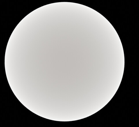
Rp:
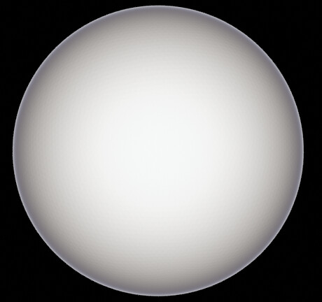
R:
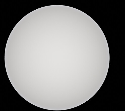
Gold:
Rs:
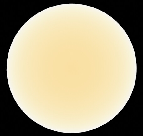
Rp:
R:
Copper:
Rs:
Rp:
R:
They all show vaguely the same thing.
The angle node looks like this (had a minor error in that but it wasn’t the thing that caused the problem - should be fixed now)
(I also tried bypassing that Mix/Normalize term that’s for roughness and at 0 Roughness it gives identical results as desired - at 1 Roughness it ought to uniformly give the F0 color which it currently doesn’t, as far as I can tell)
Copper and Gold are actually already on the test material, easy to switch in.
as sayed, iron is reflecting around 50% .The preview looks too bright.
It’s not just too bright. It also seems to work in an unexpected way, right? The center ought to be the darkest part. Which it currently clearly isn’t. I just don’t know where the error lies. Bit at a loss
Yes the Rp looks kind of inverted,the colors are better vs the old purple though.maybe a inverted incoming view vector could help?
For sure, yeah. I’ll try starting from scratch and see if that fixes it…
PFF problem found. I forgot to multiply the term that currently was called Rp with Rs. Silly mistake. Now I get something like this
Shader:
Blend file:
https://www.dropbox.com/s/hue7ozz0mz3783n/Complex%20IoR%202.blend?dl=0
Overexposed (to show off the deep reflections)
Not as bright
RS:
Another sign that this is correct now, besides these much better looking images:
It no longer takes forever to render at roughness 0. Previously it would take insane amounts without roughness. Presumably that’s because it didn’t conserve energy.
Also fixed the rusty Suzanne file (same file as before, just linking it again so you don’t have to dive for it):
Blend:
https://www.dropbox.com/s/h3tduu9wc3ao731/Suzanne%20Quick%20Spectral%20Test.blend?dl=0
shiny version:
rougher version:
(Note: these are denoised as there were quite a few fireflies especially in the siny version)
And finally, I did a torus shaped “furnace” of gold:
I build a new equation,Rp and Rs looks correct too (non inverse)
(a * b) / c = a * (b / c)
If both of those were divisions, this would be something to be careful about.
For symmetry reasons I prefer to first consider the fraction, then Rs as a factor on top. But doing that you showed there will work just as well.
I added a silver sphere and now I got a lovely Wada Basin
(POV: camera in the exact center between the spheres, looking down at the plane below. 360° camera so the “outer ring” is actually the silver sphere on top. Top left is copper, bottom left is gold, right is iron)
If you get the scene above it should now include that silver sphere
Trying to kinda fake glass in a weird hybrid method that’s totally not accurate but it’s something.
My question, though, is whether my logic at least checks out.
I’m doing this right now:
So in words, I take the reflection spectrum, use that as color for my reflections,
then I take 1 - reflections as my transmission spectrum. The light that ends up going through the material.
I think I can essentially add them together as, together, they account for all light.
I then split the transmission spectrum into red, green, and blue components as I would do if I wanted to fake dispersion in regular Cycles. This is, of course, extremely silly if I already have spectral capabilities, and also because these colors are now represented by multiple wavelengths each, but as far as I can tell that’s the closest I can get to “proper” dispersion right now.
The whole add and divide of pure primary colors is just to make sure these spectra are actually summing to 1. I’m pretty sure that’s the case anyways so I probably could skip this, but since there’s some weirdness with the upsampling, I thought I’d make extra sure.
Slap different IORs at specific representative wavelengths (450 550 650 nm) on the three refractive shaders accordingly, add it all together. Done.
I think this isn’t messing with energy conservation at least. (Beyond that it’s clearly bogus, but I hope to at least accomplish that) - do you think that’s (in that sense) correct?
I probably could actually refine this by splitting the spectral wavelengths up into finer pieces, come to think of it. Anyway, the outcome for this looks something like this:
Not super exciting for this particular material / shape but there you have it haha
You could simply input the same IOR nk values into a glassshader.the advantage is that the glasshader does the lightrefraction (lens bend effect).
I guess the nk spectrum output take just the summerized value of one weighted n and one k value?
if yes,then you got no chromatic abberation,because its like every normal shader with one IOR value then.
It needs to be driven over the whole spectrum inside the shader.Important is for the refraction effect, that it occurs with different IOR (similar like the reflection but now for the refracting transsmission part) and wavelegth.
You can split it to trichromatic like in many online tuts.Better would be if we could make use of the nk spectrum,but dont think due the closure of the shader we can not make use of it?!
you can find many glass values of IOR at refractive index site too.
https://refractiveindex.info/?shelf=glass&book=soda-lime&page=Rubin-green
Nope. The glass shader only uses a single IOR value. It’s currently impossible to plug in complex IOR values to get this right. I’d have to use multiple glass shaders.
But the reflection I can already get down “perfectly” using the complex IOR shader I already built.
So instead, I can separate the reflective and refractive part, getting the exact right reflections, and approximate multi-pass refractions.
This is precisely what I’m doing in that screenshot right now.
Already using that. That’s how I got my reflectance-, and derived transmittance spectra.
yes should be working.
ofc,i meaning the (n) spectrum node we have used for the conductor shader.
I’m already using that
Yes, this should be optimized,to make use of the whole spectrum,and without splitting every build into trichromatics.
maybe a spectral input for the mixshader would be a good start.And a fac input for the spectrum node it can be driven somehow,like a colorramp can.
I know what needs to be done on a features side. Right now I’m concerned with making it work with our current limited features haha
Shouldn’t iron oxide be rust? Which is what I already used in that file? haha
looks neat tho