Finally, a new build is available on GraphicAll. This one took a bit longer than I expected. Changes:
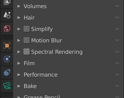
Added an ability to switch between RGB and spectral rendering modes. This is done by compiling RGB and spectral rendering kernels separately, meaning there should be no overhead when using RGB mode. As for now, CUDA supports only spectral mode. You can switch between using a checkbox (which is off by default, I haven’t figure out how to make it checked).
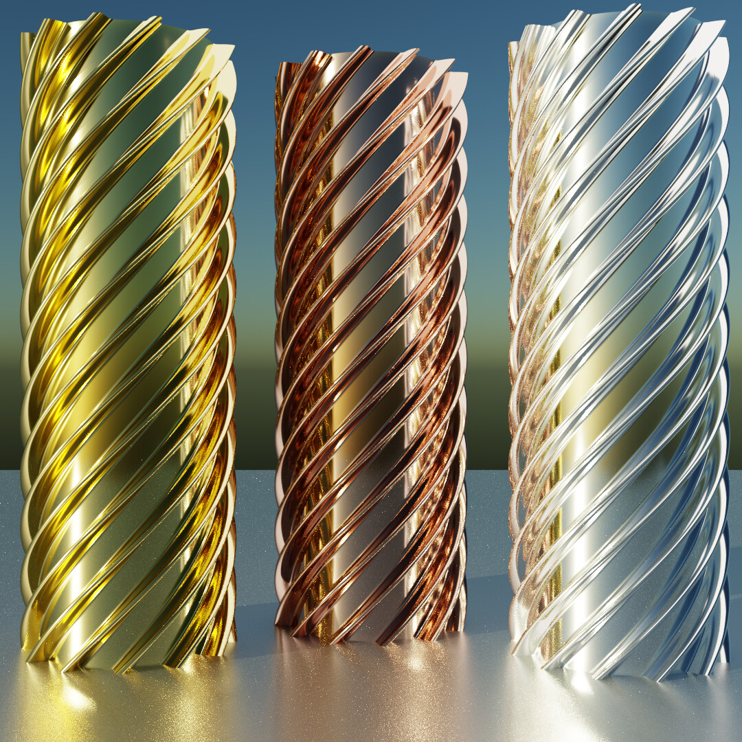
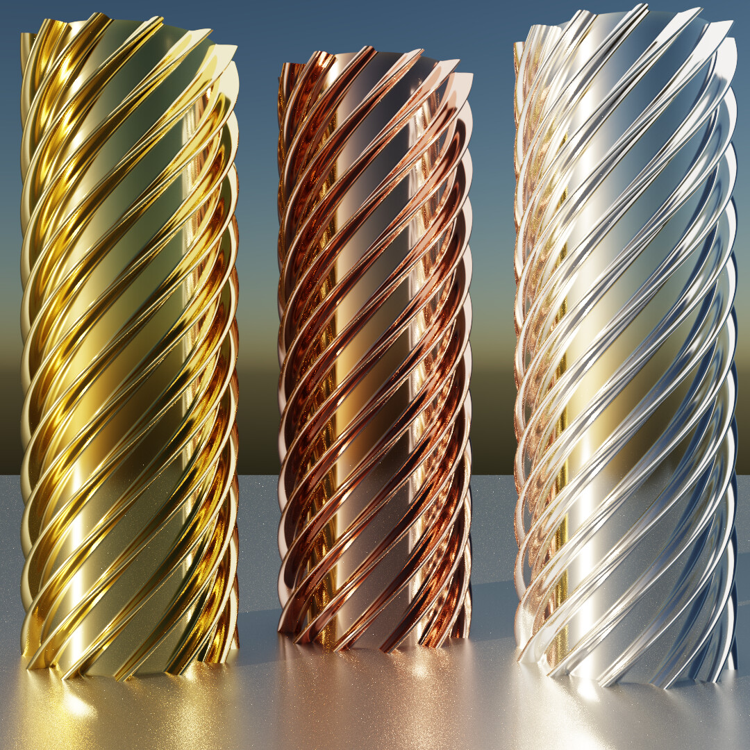
Updated RGB upsampling LUT to reduce color differences between RGB and spectral renders. It’ll be replaced with a better upsampling technique in the future. Comparison (thanks to @kram1032 for the test scene):
Fixed render passes bug that made them colorless, though there’s now much more color than should be . I suspect the reason is the incorrect RGB upsampling, which will be replaced anyway.
Fixed “Import spectrum from CSV” plugin incorrectly importing values outside of the default spectrum range.
Removed the usage of Intel’s SVML library. If you had any compiler errors due to some _mm256_* functions, they should be gone now.
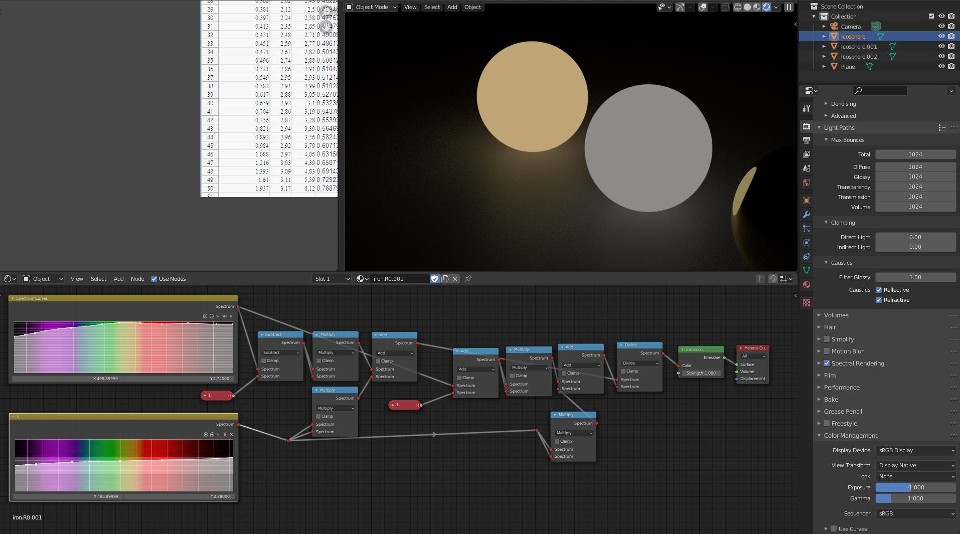
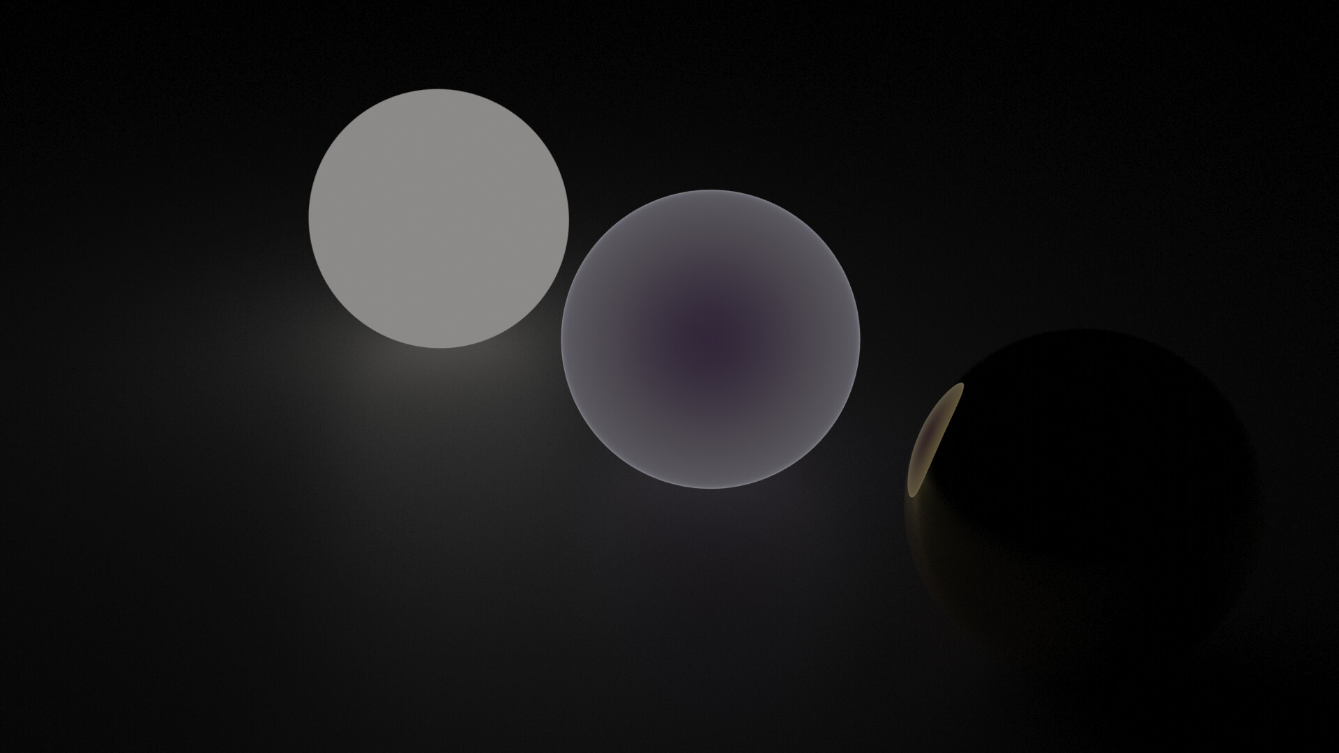
Don’t have much time right now but I tried an Iron Complex IOR and it’s weirdly purple?
Like, I like it, but that’s not what iron ought to look like I’m pretty sure. I wonder where the problem lies.
Also I’m not sure the fixed render passes were entirely an improvement: I now get Dif/Glossy Direct and Indirect to look roughly right. But both Glossy and Diffuse Col just render black for spectrally defined materials (i.e. those that use spectral curves rather than spectrally upsampled RGB - previously they gave some reasonable output)
the best would be to “plot” out the reflection result to a emission shader,on a plane or some measurement model, that displays the wavelength range you can read/compare.
IE,if the plot is the same as the calculated reflection,from the refractive index site.
I mean it’s clear at a glance that it isn’t because iron isn’t this purple
I might have made a mistake in the n k values though. I’ll have to double check
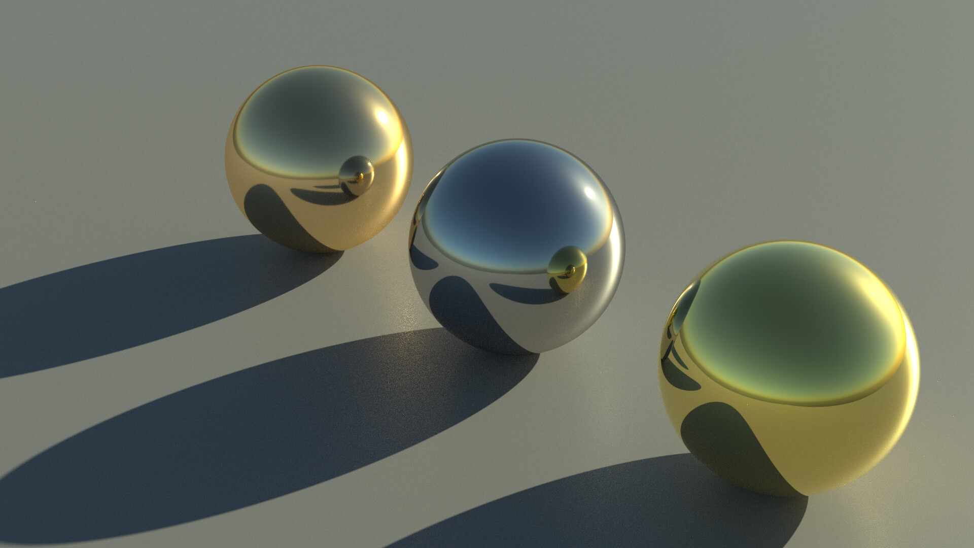
I have downloaded your testfile and added the math for R0 calculation,to compare the results from the refractive list values.
Left is gold with nk from your preset,the right is Iron from the list.Backround light is 0,emission at 1.the emission output is around 50% higher as expected.(around .5 for Iron is renderpreview around .75).with exposure at -1 its closer (.55).Not sure if its gamma correction(is no option to deactivate the display gamma),or the math nodes(the math is correct,could be internal wrong),or something else.The color appearence seems right though.
Yeah I hope @pembem22 will add the missing options back in. They were removed because they were deemed “wrong” but I think that was without considering just how long it’d take to get a fully satisfactory version of spectral filmic.
For now what you gotta do is to render stuff out as multilayer exr and then import it into regular blender where you use the compositor to get whichever scene transform you want.
The colors in that exr will be the ones before color management. If you check values in blender’s render output viewer, the left-most values are linear and they tend to be much darker than the labelled CM (Color Management) to the right
Anyway as far as I can tell you did the exact same inputs as me, just with slightly less precision (shouldn’t really matter)
I get a very clear purple tinge. So right now I’m not sure where the mistake lies. Since you get a perfectly plausible grey value, perhaps something still is wrong with my Complex IOR math here
EDIT: Ok I had some things wrong there still (totally forgot to plug in the normal)
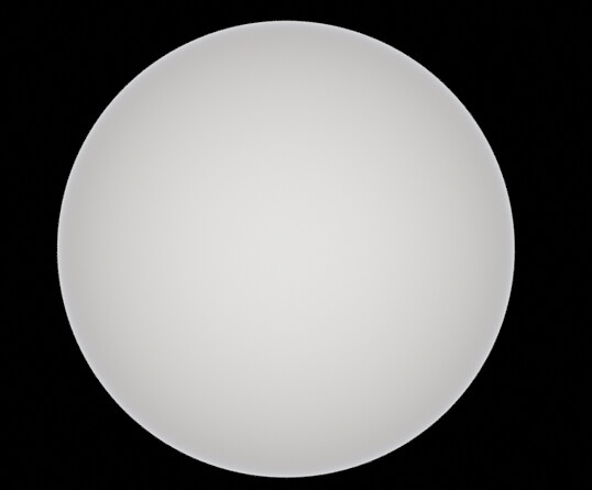
And then I accidentally had some nodes exactly covering each other (seems like the only way to spot this is to wiggle around each and every node and find that, oops, there’s something below) and now I get this for R:
I think something still is wrong though. It looks like it goes white in the center and dark at the fringes, as if the cos and sin inputs were inverted perhaps… But as far as I can tell, they aren’t.
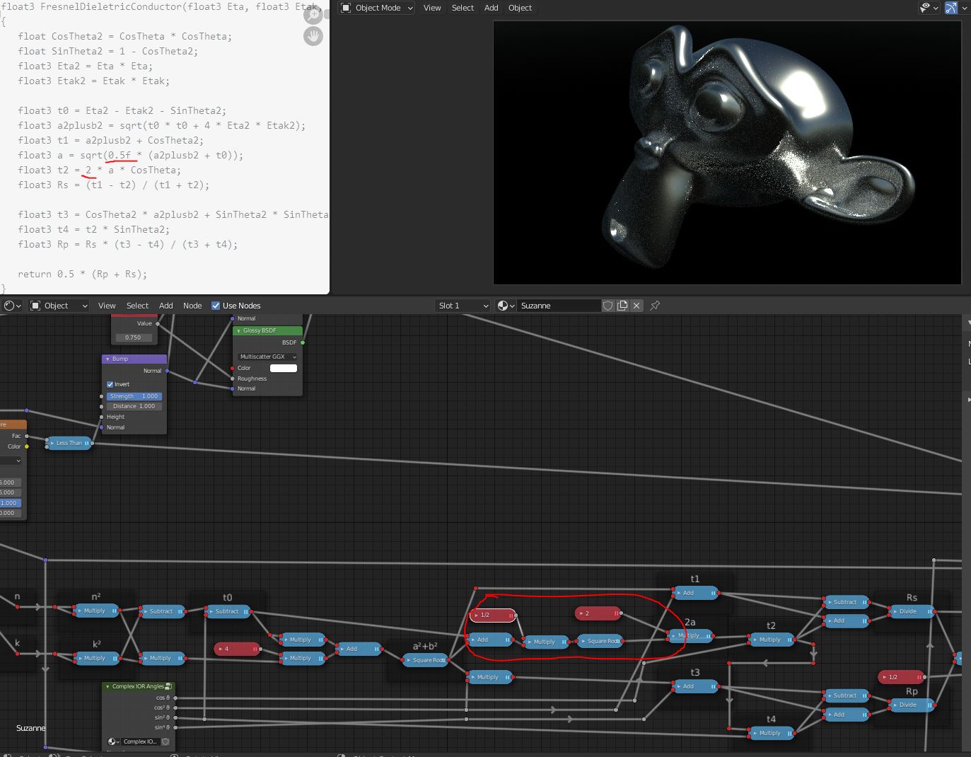
EDIT: Ok at this point I don’t see what, if anything, would be wrong. What I got is this:
As far as I can tell the result that looks like what I’d expect is stored in Rs. Rp makes the center much brighter, leading to R being quite bright in the center.


 . I suspect the reason is the incorrect RGB upsampling, which will be replaced anyway.