I do believe I recall the Fresnel induced rim reflection being more pronounced on dielectrics than on conductors though. Might have more to do with it being less saturated on dielectrics tho.
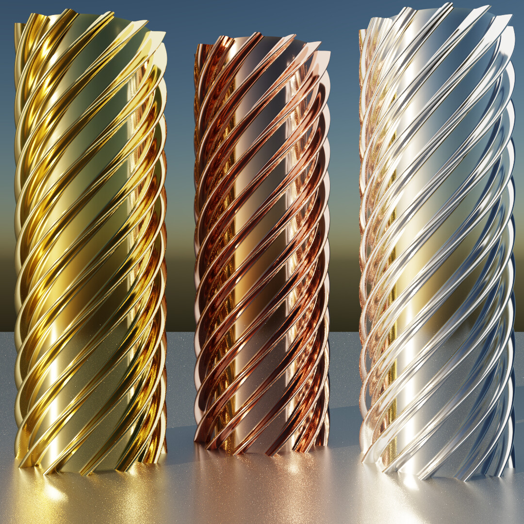
Perhaps, but I visualized it:
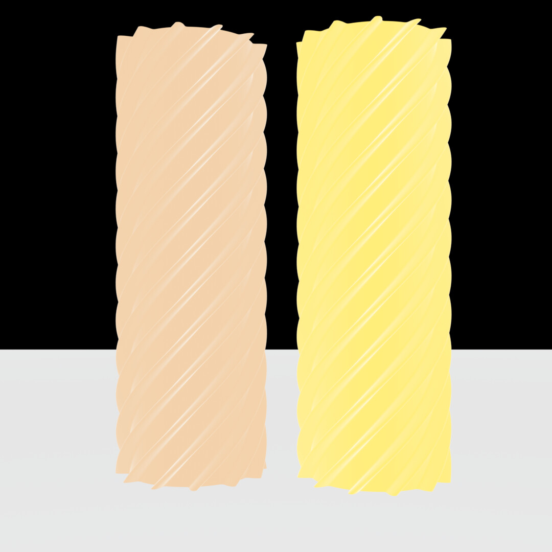
it’s quite clear that all three of those materials go to basically white at the rim. It looks like pixelgrip’s gold material, before clear coat, is kinda doing the opposite?
Yes, at the very edge it should go white no matter what, since virtually none of that light/energy is lost to the material surface. edit: unless diffraction occurs I guess…
(still working on the rigorous test scene - no worries - but I’m a bit overloaded with computerwork these days) But an update nonetheless.
I was inspired by the nice Fresnel related renderings and wanted to combine that with ‘multiple’ refractions in an easy-to-understand rigorous test scene. This blend (Unique Download Link | WeTransfer) has a camera looking down in orthogonal view at five 45° slanted dielectric planes of 1 cm thickness and a sun-light from the far left. Many more planes can be added if needed.
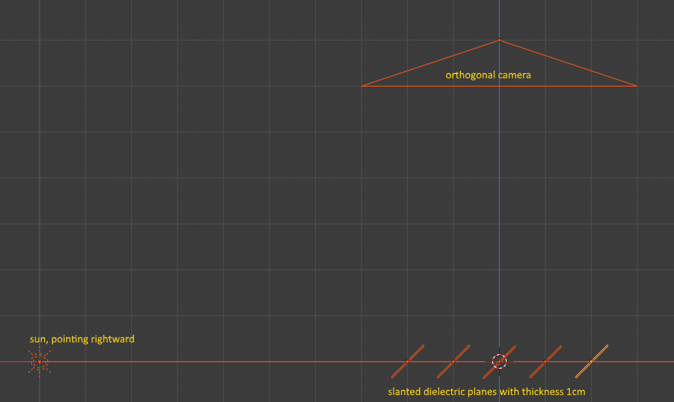
Each dielectric object has a very specific IOR which causes 10% reflection of the initial sunlight towards the camera and 90% transmission towards the next object. That means that the right-most object needs to have the highest IOR in order to achieve the same reflected amount. Note that multiple reflections are at play within each dielectric object, which is accounted for in the pre-calculated IOR values. Basically, this blend allows for testing the Fresnel equations within Cycles in the context of infinite(?) reflections and refractions. In the end, after doing a full render (should be fairly quick), all objects should be rendered with the same gray value. RGB-Cycles passes this test:
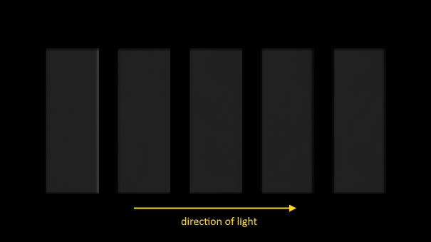
I hope this is helpful.
4 Likes
I love how hyper-engineered your tests are
1 Like
My carpaint shader is a multilayer shader.The paint layer ,next layer the effect and flakes,and on top the clear coat.
I have added a optional weight to some layer,like the clear coat,so i can render preview the layer underneath the clear coat without clear coat.
However,the layer system is based on the IOR.The clear coat has a IOR of maybe 1.5,now the light is reflecting some part of the light due the IOR,the refractive transmissive part is the ratio what was not reflected,this is what you can see at the gold render without the clear coat(the amout of transmissive light due IOR on the goldlayer underneath).This is energy conserving.Not like the Principled clear coat what its added on top of the shader.
To simulate direct light to the goldlayer i have to set the clear IOR to 1 like air.
hm i think i found a error (0 division) if i set the clear to 1.because (n-n)²/(n+n)² is (1-1)² =0 /(n+n)² =0
This is how my Multilayer works.
I’m not sure how complicated your setup is but wouldn’t it be easier to just simply remove that one layer for now? Like, drop the mix shader for it?
Handling IOR between various interfaces correctly would be really nice to see in Cycles. I modelled a glass of water once, where I made the inside have “lower” IOR because it’s actually going into water, not air, and it made quite a difference to the look. Fiddling with that manually is rather annoying though. I wish we could just have intersecting geometry and tell Cycles “oh but actually this one’s “the real geometry” and the other actually stops where it stops” and it’d automatically do the correct calculations.
And this careful account of the correct IOR values across multiple layers would be great too.
Does your multilayer shader also account for layer thickness? (Is that even possible, currently?)
1 Like
Yes and No.Yes,you can calculate the behavior the material has,like the IOR,this way you can calc the ratio amount of reflection and transmission.Like the test from Ivo.
But since the light transport itself is a closure thing,we have no direct access to the light vector or its half vector for diffraction calc ect.we can not calc internal reflections ect.
You can as sayed calc how much light goes through the layer,and how much gets absorped.
I have implemented additional the possibility for absorption with thickness in my clear coat layer,and the layer underneath are affected by it too.
At blenderartist someone made a thinfilmshader based on multilayer matrix iirc.
I have rebuild a thinfilmshader from a c++ code to cycles too.Its calculate the wavelength shift inside a material based on its IOR and thickness.Its based on three RGB lambdas.IE like 450,550,650 nm.
Not sure, how this could be usefull changed for spectral,since these would need a row of data like the refractive index samples list i have posted before.And for display we would need the RGB result too.
Here you can download a conductor shader,i have builded.
btw a better way to setup the material.someone notice the need of a trichromatic/spectral input for the mixshader? wink
1 Like
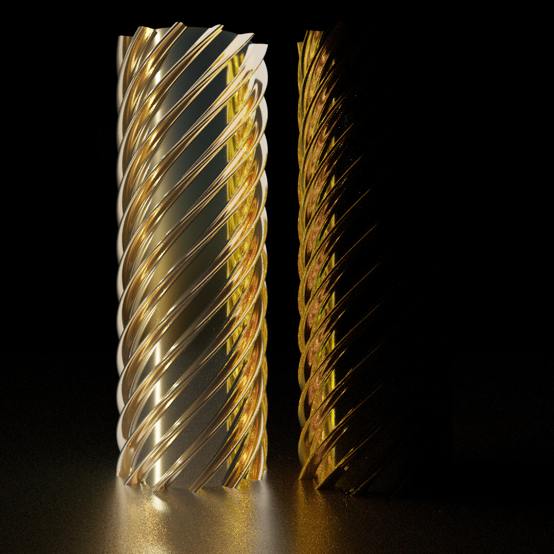
I slightly changed the lighting, relied on Multiscatter GGX, and gave these materials a bit more roughness. The aluminium screw I replaced with a spectral fresnel golden one (as I put above) to directly compare it with your version of gold here. Looks like your gold is far too reddish. Almost a bit copper-y.

In this version, I used that approximation to a color weighted mix shader
And the diff for good measure:
(Note, however, that this relies on the R G B colors that you get from spectral upsampling which isn’t quite equivalent to how it would be in regular Cycles, and also, as we established, the red and green channels are slightly wrong right now)
EDIT: Also, the Col-only versions (emitters instead of glossy materials), showing off clearly, that these accomplish roughly the same thing, just with different actual colors:
2 Likes
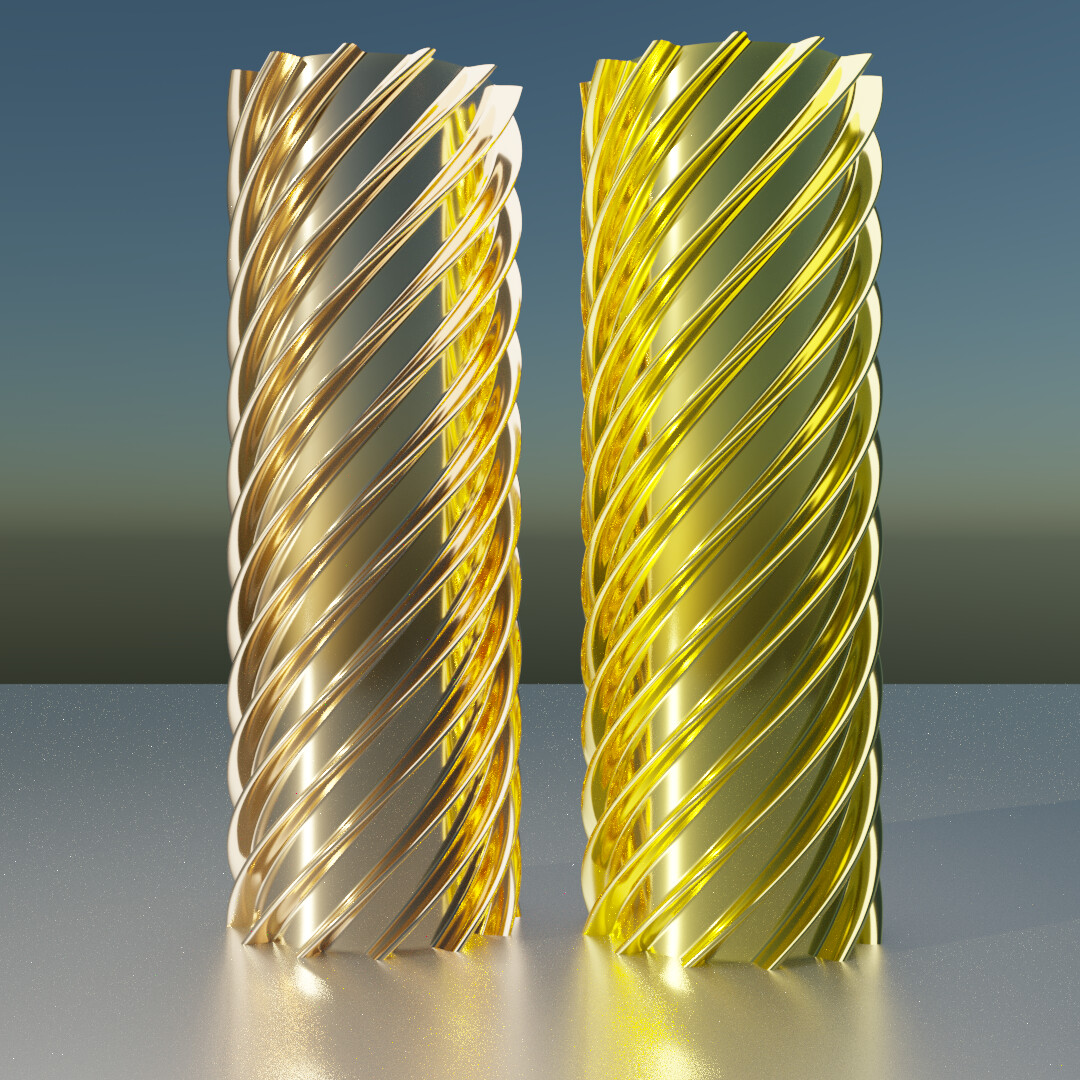
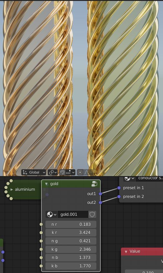
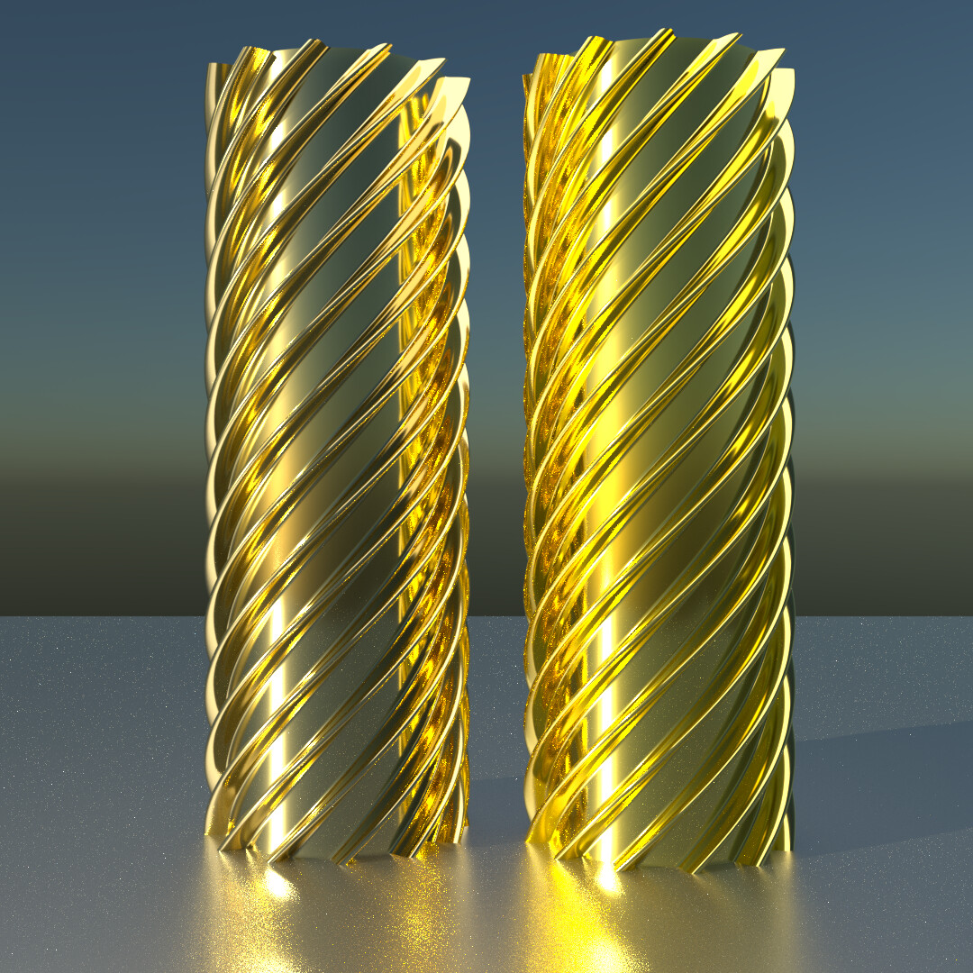
Ahh,i forget to say that the preset is slightly different.Just put the same values from my first gold post in(carpaintgold1).These are rgb nk values from the refractive list (0.45,0.55,0.65 micrometer).
Left the redish preset,on the right the refractive values
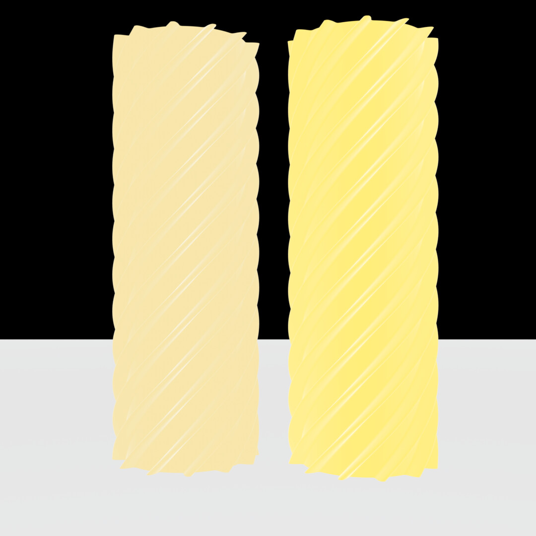
Ok I corrected this now. The results are still too reddish and also too pale, but far more plausible:
Col:
single weight shader:
RGB weight shader:
Diff:
Interestingly for these values there is a much greater difference in the green values between the two differently weighted versions. The bottom left of the diff has a pretty significant green cast
1 Like
Loving seeing these experiments. Investigating whether a spectral mix BSDF could be implemented is added to the list of things to do. I can see some really interesting applications of this.
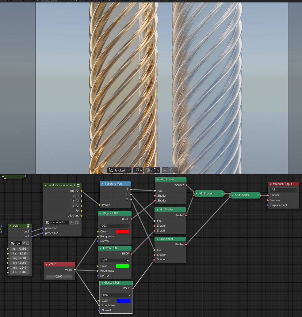
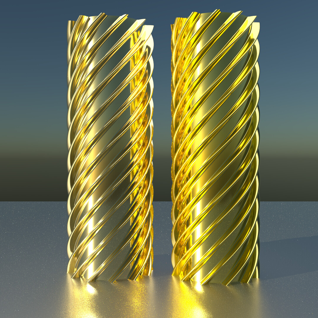
I have re checked the color output from the conductor shader vs the rgb split mix and add method.There is no color difference.These method however is usefull if you want to mix different shader.
The color output (split rgb mix add primarys) and direct color output into a color rgb comparsion,is no difference as result.
Here on the left the split rgb mix version,on the right the direct glossy color.

Oh I see. I did it a little differently and I think that means the single color version I used there is actually wrong. Either way though, both versions are still slightly more reddish and slightly paler than what the full spectral values give me
Do you use your own conductor shader for the spectral,you have posted before?that could make a difference maybe.
For comparison the best would be to use the same shader.
Left is each time yours, right is each time mine. The point was to compare your RGB-based shader to my Spectral based one.
I’d caution against making any pixel-by-pixel comparisons between RGB and spectral cycles right now, until the colour is verified to be correct again, the results may be meaningless. Behaviour of self-reflections/energy-retention might still be comparable but you would have to keep in mind the differences in colour which aren’t pinned down yet.
2 Likes
Certainly. I’ll for sure redo this test when you got that fixed
Sure,i think rendering my gold shader in RGB and then in the spectral build(same preset),could give maybe the answer for the biggest color difference with the same shader.
I mean sure. Thing is, the colors are not gonna be comparable between versions no matter what until the redness issue is resolved.
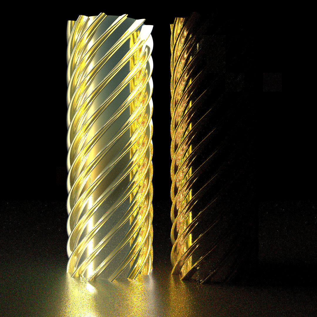
I did it anyway and they look nearly identical save for two things:
- obviously the RGB version looks much more red
- interestingly it looks like the spectral version has slightly lower noise (specifically, fewer fireflies, especially on the region where the gold and copper screws reflect the aluminum plane below.)
I have noticed that trend before already. It’s quite subtle though. This is probably the clearest example I’ve seen so far.
The third screw is silver and I made sure to copy the values over accordingly rather than relying on the preset ones.
RGB:
Spectral:

4 Likes