Hmm I don’t have the openimageio folder in the tortoise SVN install folder in program files, is that where it’s meant to be?
I should have said “our” rather than “the” svn libs.
1 Like
I’m not sure if this now focuses too much on scattering but how is that?
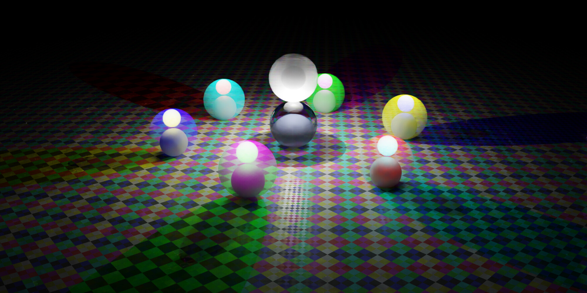
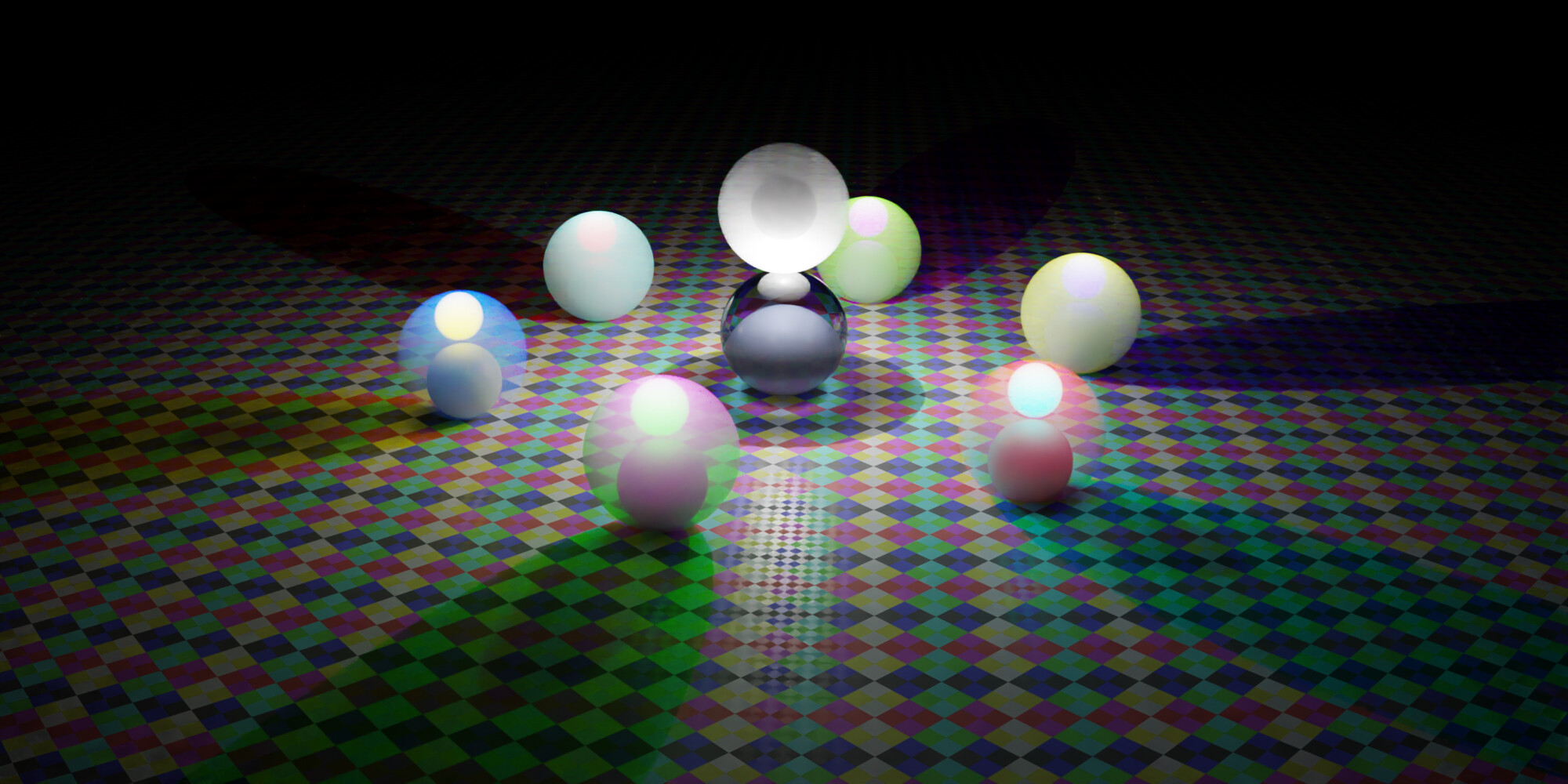
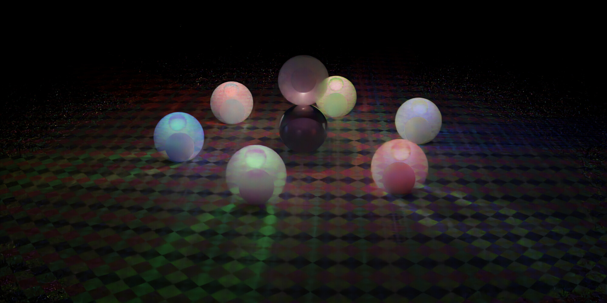
RGB:
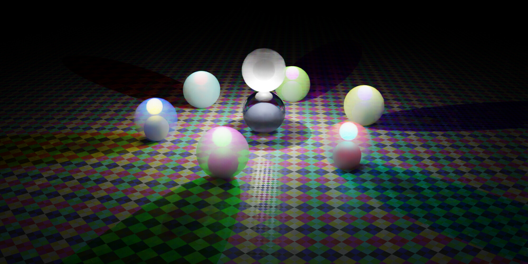
Spectral:
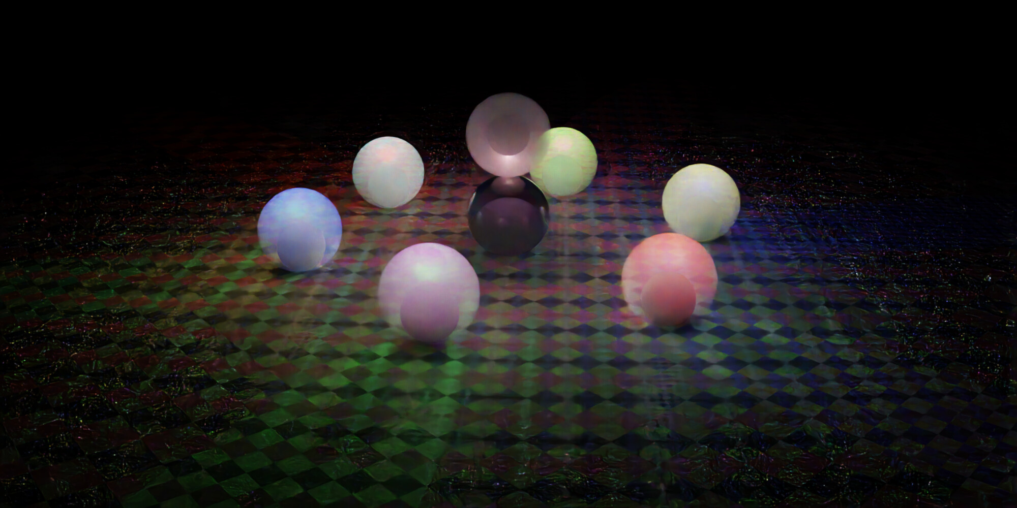
Diff:
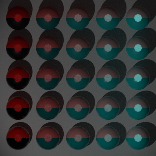
The six balls on the ground scatter (very nearly) pure RYGCBM colors (density 20). They each also have a grey (0.5) ball and a white emissive (strength 10) ball inside them.
Additionally, in the center, there is one ball that features an absorptive glass ball with a grey (0.5) ball inside, and, right on top of that, another scattering ball, this time in pure white (density 1.5), with another grey (0.5) ball and a white point light inside. In at the very last that case, you can also clearly see some volume shadows now.
It’s very obvious, that the spectral version of scattering ends up being far more milky. As far as I can tell, this seems “more correct” though.
This also shows off why the colored chess board might be very good: You can really tell which colors are or aren’t being filtered out by any given scattering medium!
Why are the colors only “very nearly” pure?
Because, if you set any channel’s scattering strength to 0, Cycles behaves rather oddly already in the RGB version. There is a huge jump in behavior from, say, RGB (1,0,0) to RGB (0.999,0.001,0.001). Something clearly goes wrong at scattering 0.
So instead I used those very mildly desaturated colors.
Also note that the pure white scattering ball and the blue glass ball below each have a red tint in the diff. I’m not sure if this somehow depends on the view angle but that seems odd to me.
3 Likes
Is this patch gonna affect spectral rendering somehow? https://developer.blender.org/D9932
I’m a bit confused by the mention of six-way MIS due to three separate channels sampled two different ways.
It is difficult to read, but I guess it doesn’t matter much as you’d choose one of either R, G, or B in RGB-Cycles or one of the 4 wavelengths in Spectral-Cycles, oh and do that 3 or 4 times respectively. So Spectral-cycles would do 4 times 2 methods for 8 MIS samples? Or choose 3 out of 4 to arrive at 6 after all?
What’s the point of these?
Spectral rendering on its own isn’t enough to give us that kind of detailed caustics. Dispersion, if BSDFs are going to be extended with that in mind, will surely benefit from this, but non-trivial caustics will remain elusive until Cycles gets a new sampling strategy aimed specifically at finding such light paths. Which this project doesn’t do.
1 Like
Could you pls stop with these ? 
We know what caustics are. If we wish to see caustics we’d google them.
If you want better caustics in your render use luxcore.
Your thread is enough.
1 Like
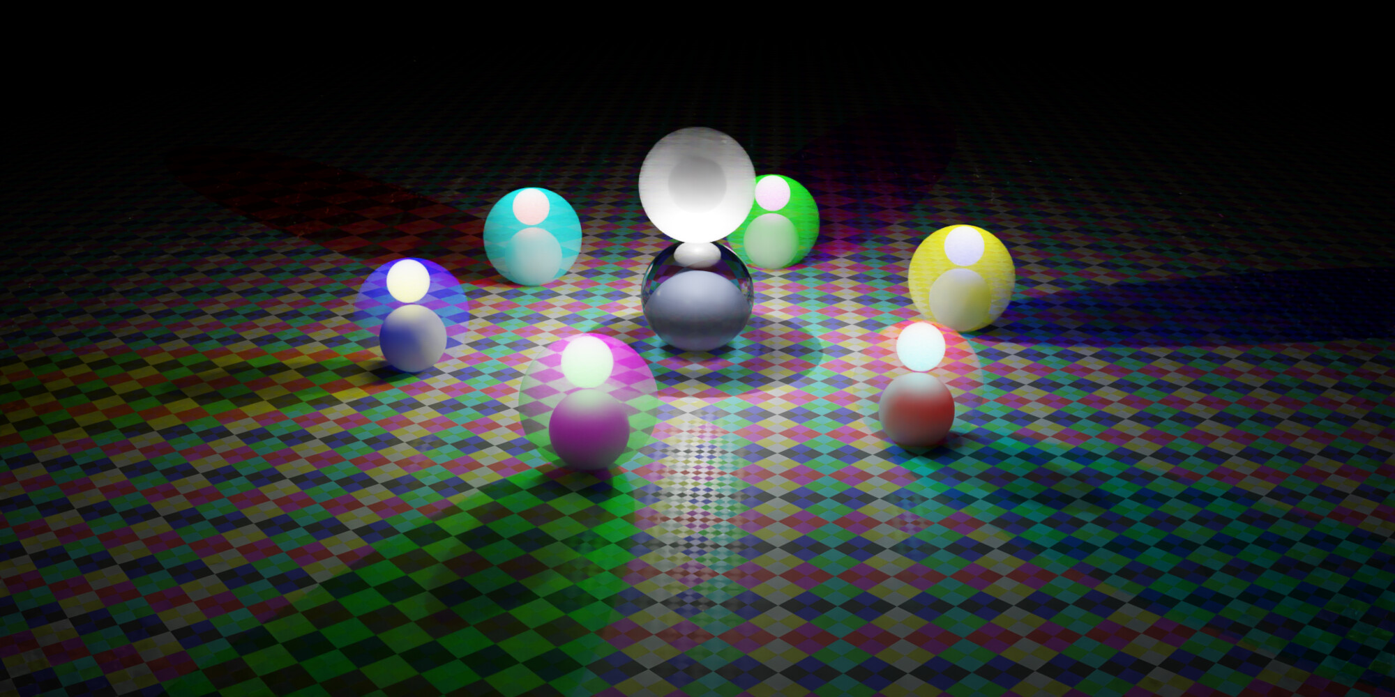
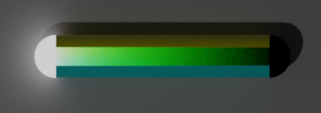
OK this might be close to final. I designed this to be backwards compatible so no spectral-exclusive features are being used. I’m also not testing Volume Emission in color here. It’s all white.
But Volume Scatter and Volume Absorption are tested in all the extreme cases of RGB, as well as white/grey.
RGB:
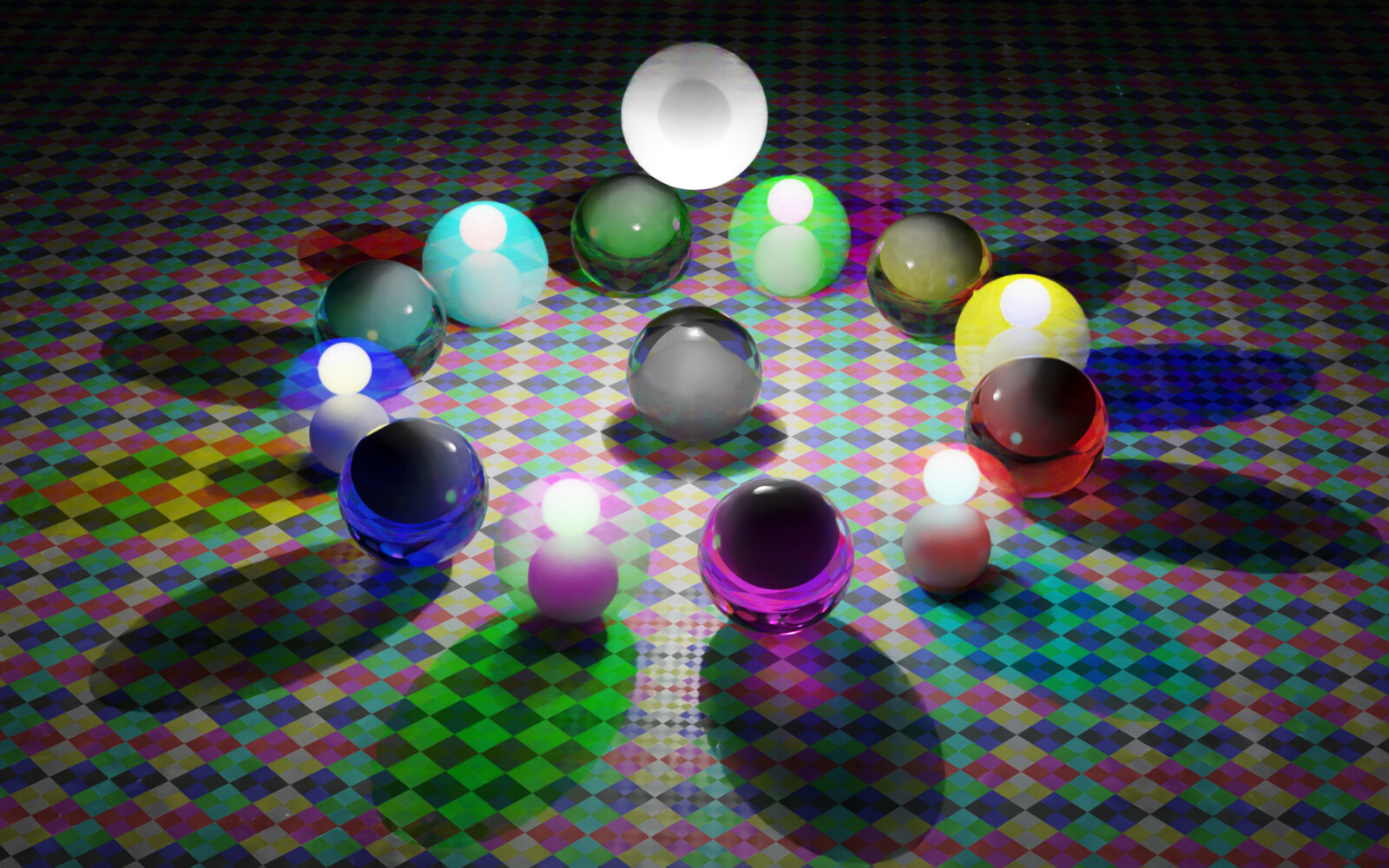
Spectral:
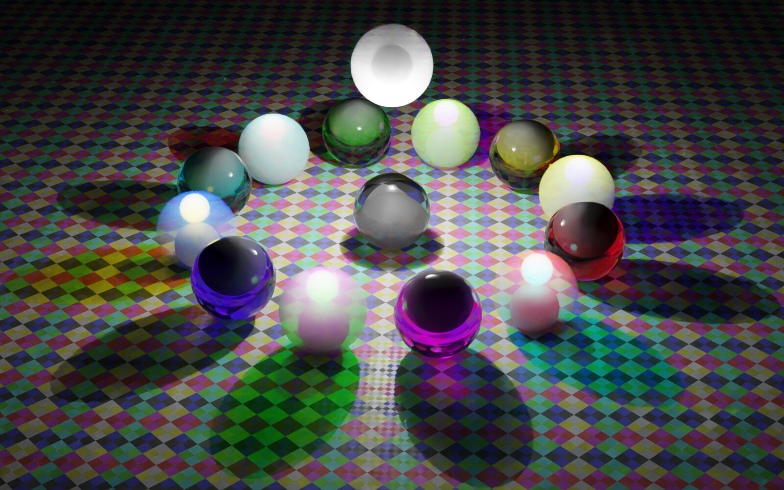
What do you think? Will this work? Any requests for tweaks?
It renders relatively slowly (I only rendered to 128 spp with denoise - without it takes a LOT more than that) but that’s sorta expected seeing as how it features scattering media.
One thing I find quite interesting:
Compare the yellow and blue scattering spheres as well as the blue absorption sphere.
The yellow scattering sphere casts a blue shadow which appears purple in the spectral renderer.
The blue absorption sphere appears purple in spectral rendering.
But the blue scattering sphere (with yellow shadow) spectrally actually tends towards cyan!
General color trends seem to be:
- red is slightly darker, spectrally
- green tends to be slightly more yellowish (compare the title colors wherever the tiles are green but not in shadow)
- blue tends to be purplish
4 Likes
Ok, this has become a little experiment really.
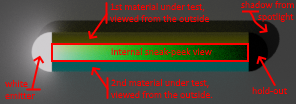
I figured that I could make little ‘furnaces’ to test BSDFs while also showing the normal appearance. What you see here is a grid of spheres where material colors change from West to East and roughness changes from North to South. Inside each sphere, there is a little point light source behind a baffle and there is a little white floor that you can see through a little opening (the orthographic camera looks top-down). I tricked Cycles to have camera rays enter the spheres through the opening at the top, but never exit anymore. Hence, any color you see through the openings is purely due to the response of the assigned BSDF(s) against the point light source, homogenized by the internal white floor that is lit indirectly only. As per the theory of energy-conservation, the light we see through the little openings should be identical from North to South and its intensity can in fact be calculated analytically. Finally, I added a global floor and some spotlight to light the sphere outsides too. Using RGB-Cycles on CPU without denoising, this rendered in under 10 minutes on my laptop:
So RGB-Cycles passes for this test . Now, this experiment is for testing surface BSDFs like I did with the conduits in my scene from yesterday, yet more rigorous. I plan to make something similar for volumetric BSDFs tomorrow. Thereafter, I want to combine my three efforts into an ‘overview’ test.
@smilebags and @kram1032: Please let me know if a more rigorous setup like this is useful for you.
3 Likes
Oh I suspect this is excellent! I’m not in the business of actually measuring so probably @smilebags and @troy_s are gonna have to check that out carefully, but it’s an excellent idea! Well done!
I don’t believe it will be too hard to patch it for Spectral, but we will need to properly understand what it is trying to achieve with the channel selection. I believe this is a case where the spectral solution will actually be more straightforward than the RGB one, we can probably just use the hero wavelength (the first of the 8) every time since it’ll be evenly distributed across the spectrum.
I think this is perfect, thanks a tonne. It seems easy to spot the differences and it tests a lot of different light paths.
I’m not sure I fully understand how to ‘read’ this image but I like the idea of the testing of indirect light. Are the dots in the middle of each sphere showing an internal scattering volume or diffuse colour? Or something different entirely? Maybe seeing the scene from a different angle would help me understand it more.
If I understand right, the circle in the middle of each sphere is a white (1 1 1) plane that, via lightpath trickery, is made to be visible to the camera but to anything else is completely shielded from the outside.
In sphere is also a point light which provides its illumination to the inside of the sphere (that little circular window is thus entirely independent of the lighting you see on the outside of each sphere)
So the color of that window depends on only the walls of the spheres and, apparently, the roughness of those walls.
It’s kinda like how blackbody colors are technically only exactly correct for inside a cavity of a specific temperature. There is no way to actually exactly produce it. You can, however, get rather close by basically heating a sphere with a tiny hole and measuring the light that escapes at that hole. The smaller the hole, the more accurate your measurements are gonna be.
Effectively, Ivo did something like that (though not with heat), and managed to reduce the hole-size to 0, getting the exactly correct result which can be predicted by some theory. Therefore you could measure the exact energy there and see if the result is what you physically expect it to be.
@Ivo do you have resources you could share where this is described in more detail?
IMO it’s definitely very obvious that volumes get lit more naturally in spectral. Which is very nice to see.
Yeah, agreed!
I somehow missed this message. As said, this renders relatively slowly but here you go:
Note: I may have gone a bit too wild with the ray bounce depth. You probably can reduce that a bunch without seriously impacting the results to speed things up at least a bit.
1 Like
@kram1032: you are spot-on with your description/interpretation of my rigorous scene. I should share (a minified version of) the scene to clarify, right?
Here it is: https://we.tl/t-j32cIbSebA
Some theory can be found in this chapter 6 “Theory and applications of integrating sphere” from Gigahertz-Optik:
https://www.gigahertz-optik.de/en-us/basics-light-measurement/integrating-spheres-theory-and-applications
1 Like
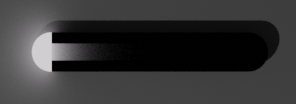
An attempt on volumetrics. Not as spectacular as @kram1032’s, but more like the laboratory test-tube version. This image shows the basic setup:
On the western side a half-dome white surface-emitter, on the eastern side a half-dome surface-holdout, in between that on the northern side a 1st surface-material under test (yellow here) and on the southern side a 2nd surface-material under test (cyan here), both 1st and 2nd material having the same volumetric BSDF under test (white volume scatter BSDF here). Again, the camera looks from the top and sneak-peeks inside the tube showing the white-green-black gradient (no light escapes the tube, so all is absorbed by either the materials under test or the hold-out. The internal light field is mostly green because the light is also reflected off the tube’s inner surfaces. The outside of the test-tube remains naturally visible and is mostly lit by a spotlight.
I don’t know the mathematics on this setup, but it should highlight any render-issues quite clearly. The ergonomics are also quite good: you can easily assign materials without breaking the precision of the spatial configuration, and a grid of test-tubes can be collated into a single view since they do not interfere with each other. Still, you can test any combination of two surface BSDFs and one volumetric BSDF.
Note that you may also choose one instead of two surface BSDFs and/or no volumetric BSDF at all. You may change the emitter spectrum. You may replace the surface BSDFs by hold-outs as well, showing the volumetric BSDF in isolation like shown here:
Finally, the blend for easier understanding: https://we.tl/t-Fhz7wlEEWk
Please let me know what you think of it.
2 Likes