Rigging orientation mismatch between Blender and other DCCs

Introduction

During GDC 2025 I was inquirying around about the struggle some studios may have with Blender. I was chasing a burning question I had from previous years: Why do some studios model all the assets with Blender, but when it comes to animation they switch to a different software?

At this year’s Blender Meetup I repeated that question and got some clues from blender user Corey Kinard. At his studio they have no problems creating and animating characters from within Blender (and using them in Unreal). However when using assets created from different DCCs (assets bought from FAB for instance), the way the bones are drawn was a real problem. So much so, that they created an add-on to mitigate this.

I got his authorization to share here the add-on and sample file, as well as the anaylisis and considerations from his team.

Links

Sample File: Unreal Mannequin (3.1 MB) (from Control Rig Samples, under a free generic license).
Fake-Bones add-on: Fake_Bones_V1.0.3_4.3.zip.
Complete Add-on Presentation.

Blender FakeBones

by: Corey Kinard

Concept

Blenders Armatures have many limitations in their design compared to industry tools such as
Maya and 3D Studio Max. While they work perfectly well for developing new rigs inside of
Blender, they aren’t as flexible and tend to have visual issues when editing or animating on a rig
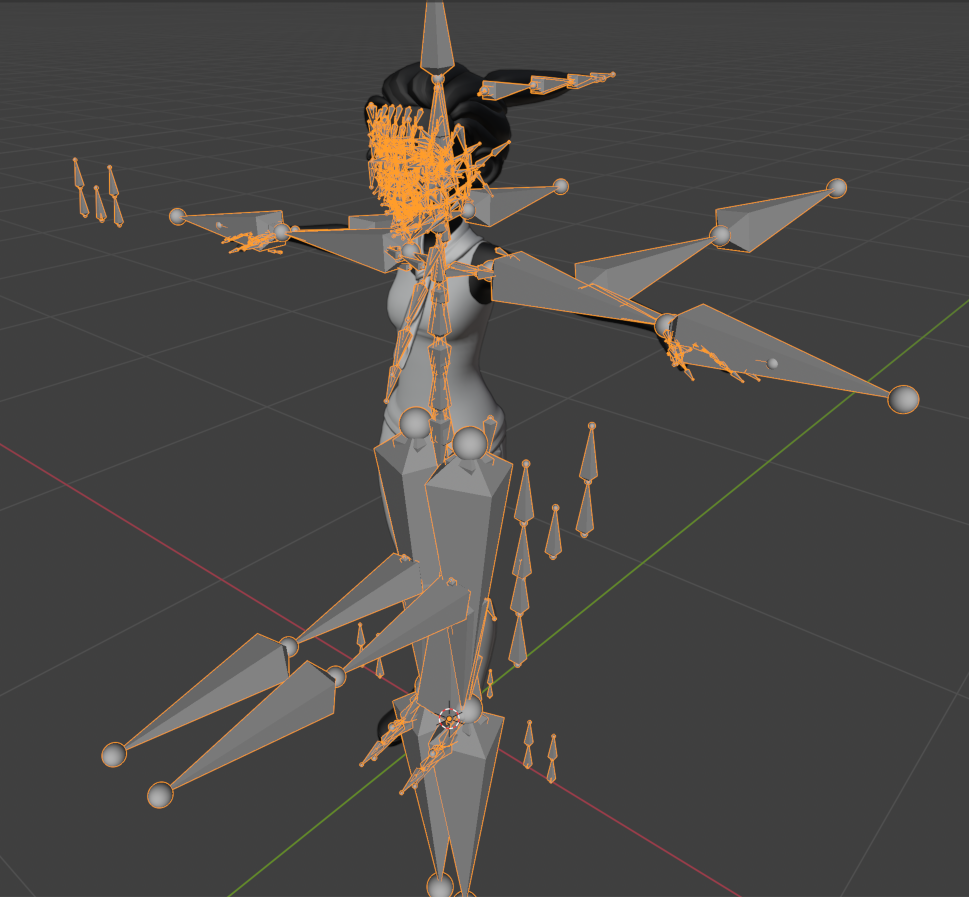
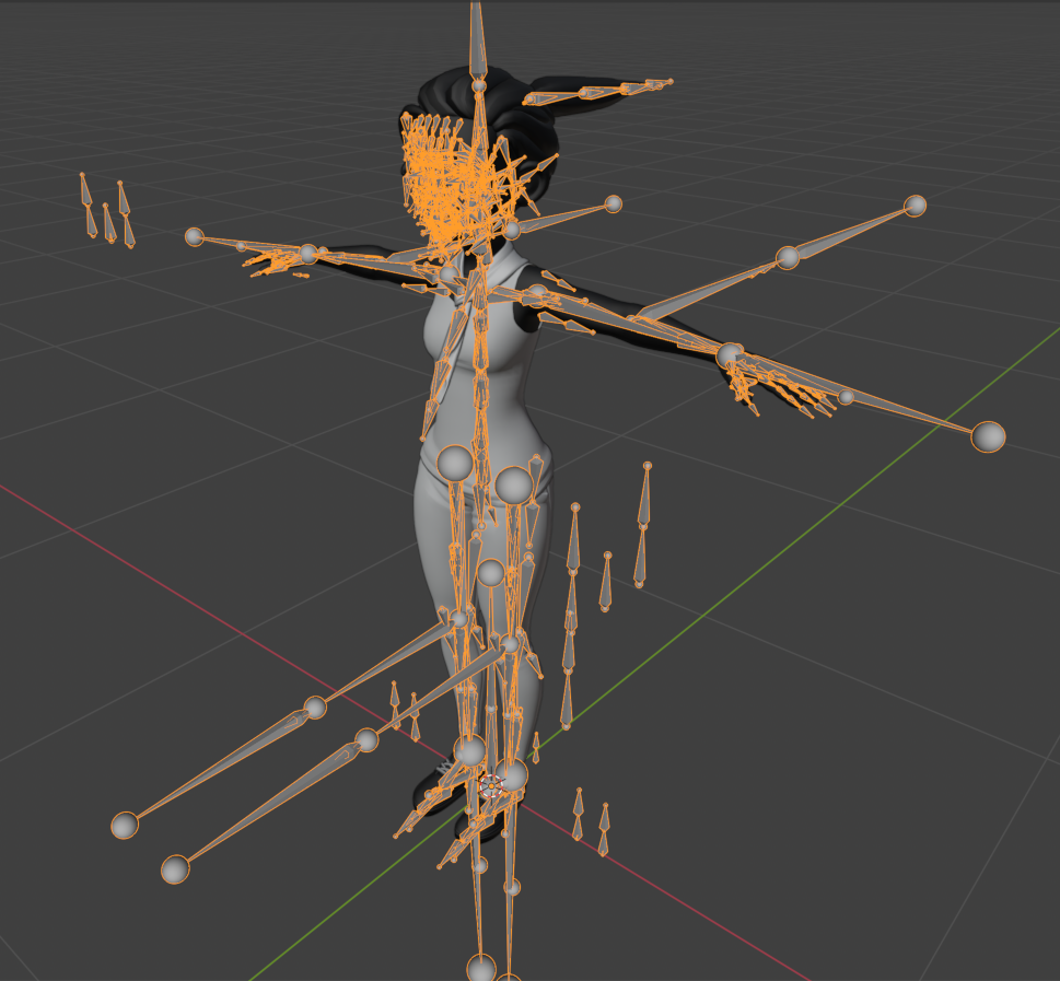
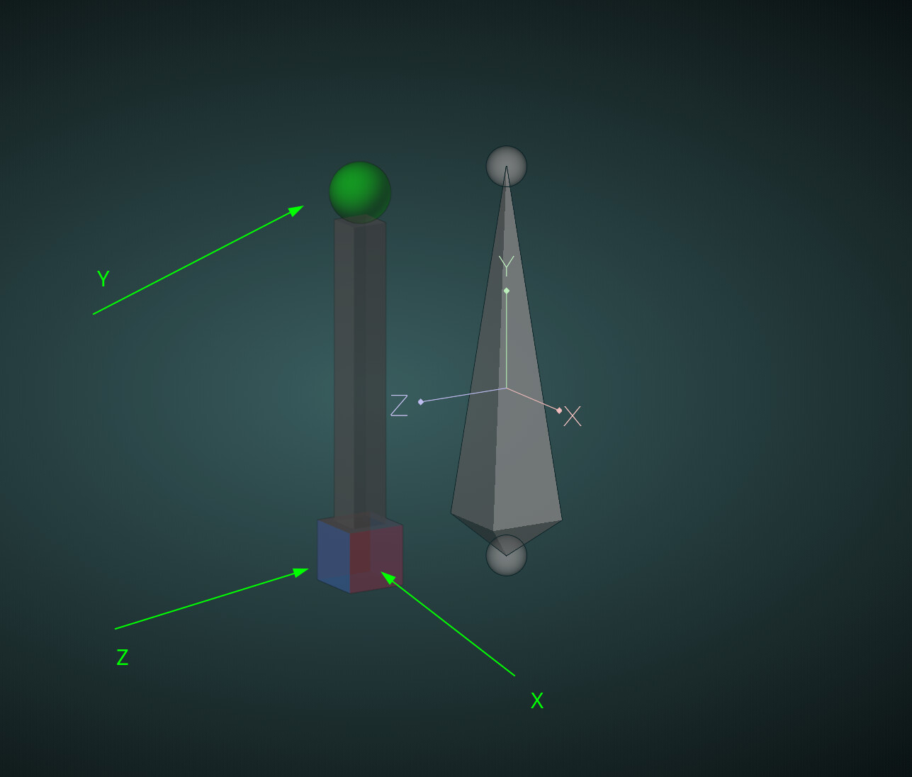
from another package (Maya/Max/Unreal). The main issue is that Blender Armatures only allow
bones to face down a specific axis, whereas in other packages you can specify any axis of
aim/orientation. The result is when an asset is imported from a content creation package other
than Blender, you get a very confusing and oftentimes mangled looking Armature that doesn’t
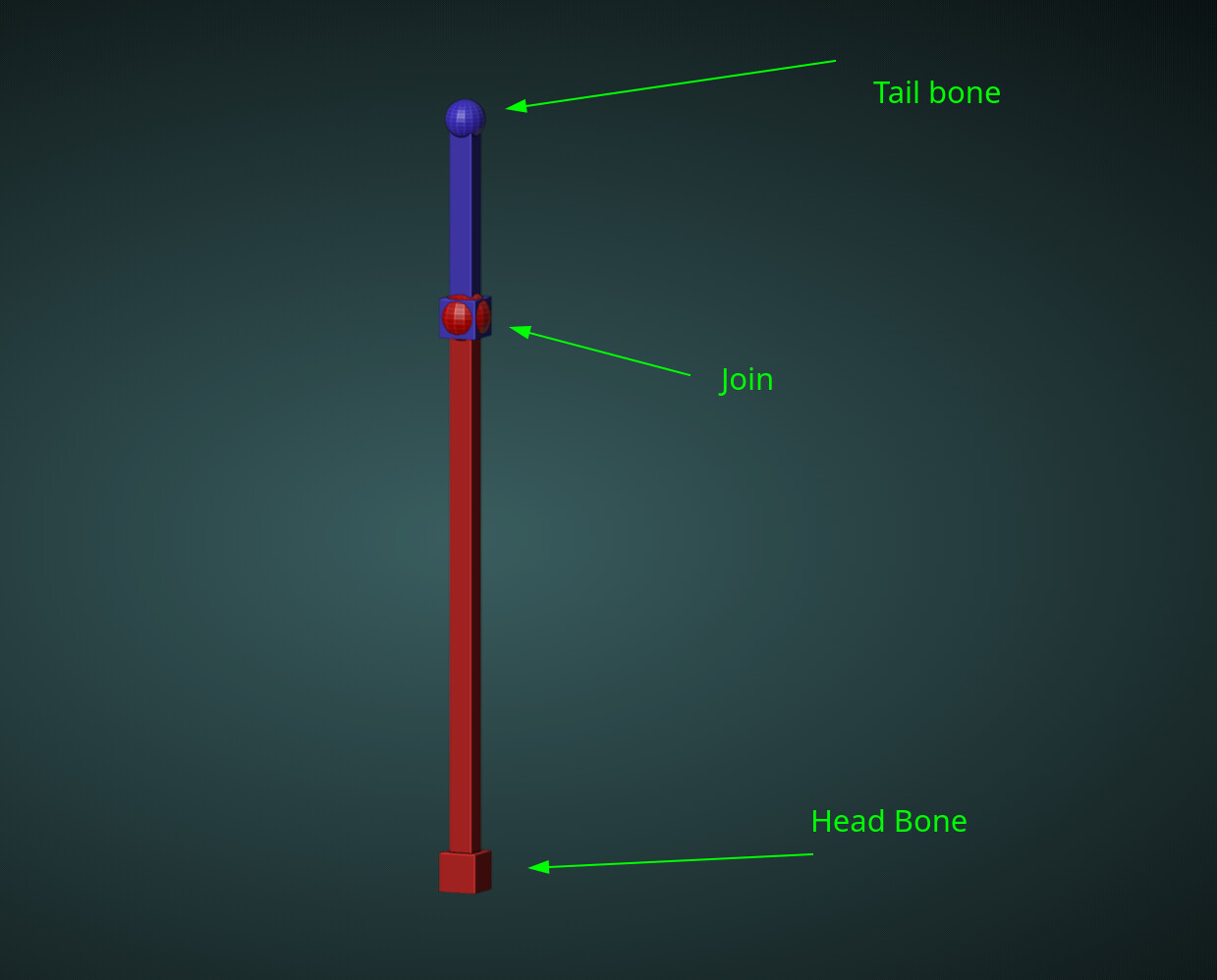
resemble the original source. The bones are in their correct location and with the proper bone
orientations, it’s just Blender has no way of displaying them like a traditional joint based system.

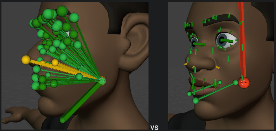
The solution is to create an addon that will create the proper visual representation of a
traditional joint based system. Here are two examples of the issue as well as the solution

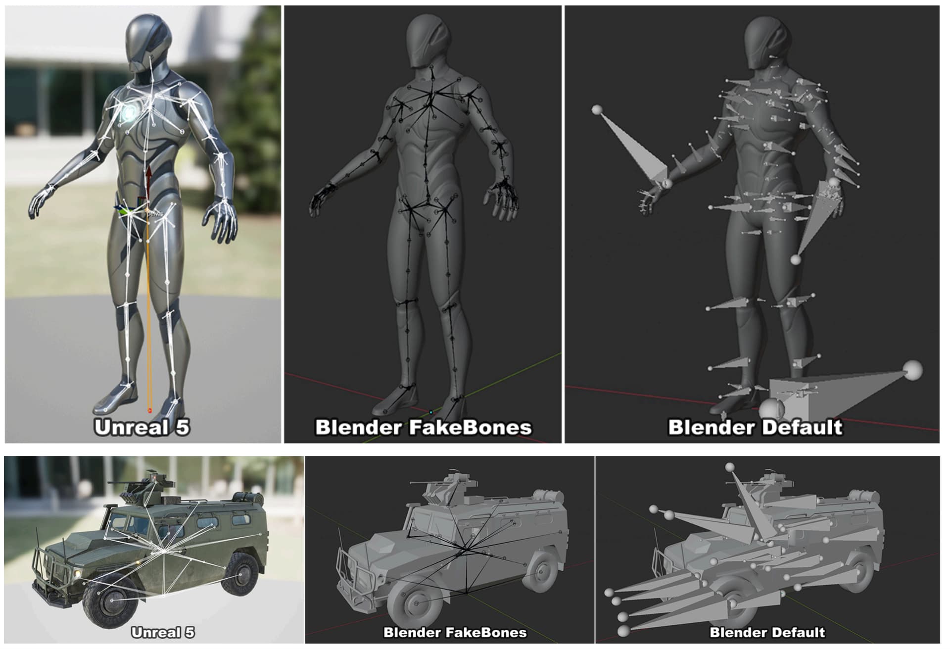
The process to create this visual representation is quite simple, but unfortunately very time
consuming and needs automating. The main benefit of this approach is that the original skeleton
isn’t altered in any way (less import/export issues), the generated empties won’t export, and
Blender Armatures IK/FK/Constraints/etc. will work.

(…)

[ the document then goes into the add-on specifics ]


Conclusion

The reason I wanted to share all this, is to make both the I/O and the Animation & Rigging modules aware of this scenario.

If we were to tackle this upon importing (i.e., with the new FBX importer) the animation data would need to be (optionally) revertable upon exporting as well. So the animations made in Blender are fully compatible in other packages and won’t require any retargeting.

Alternatively (or additionally) this could be tackled as a core animation functionality (per-bone orientation? different drawing options, …).

32 Likes

As someone in the “design your DCC like an IDE” camp, I’d vote for tackling it as core animation functionality; joint-based rigs are common enough that it makes sense to support them directly, rather than handle them purely at the I/O boundary. Especially for game development, where we re-use rigs as much as possible.

13 Likes

Another issue is that while “everything else” seems to support bone bind matrices that are per-skinned mesh, Blender does not. In Blender, the “bone-to-skin binding information” simply does not exist, which means that all the meshes that use the same armature need to be skinned at the same time and same transform.

Since most (all?) other software packages do not have this limitation, you can end up e.g. with FBX files produced by other applications, where, for example, you get a character model with several meshes (body, coat, gloves, boots etc.) and it is all garbled up since the meshes use different scale or somesuch.

There are ways around this issue (e.g. glTF importer effectively “bakes” skinned meshes at import time), but this is another one of “blender is different compared to other applications”. Logically, the missing piece is that the Armature modifier should contain the “bone bind matrices”.

16 Likes

Another issue very visible in this Mannequin file: that all the bones are displayed the same. While bone orientation arguably could be worked around and/or improved at import level, the “visibly largest” bones are all “IK” bones that span half of the body, and this makes their octahedral shapes look massive.

A part of that could also be worked around at import level, by changing the armature bone visual display to e.g. “wire”, but really if people normally expect “octahedral” bone shapes, do they really want octahedral shapes for IK bones? Wouldn’t they want to be able to change visualization option per bone, instead of all of the bones of the armature?

5 Likes

Isn’t it simpler to make octahedral not scale with length ?

5 Likes

Possibly. Someone with design opinions and animation knowledge should chip in :slight_smile:

2 Likes

Yes please! Please, please, please, please, please give us this. I use complex Blender rigs every day at work, and trying to select in edit mode obscured by a giant octahedral is an awful experience

5 Likes

I don’t speak for every rigger/animator but I don’t use octahedral specifically because it doesn’t allow me to distinguish between several of them when they’re the same size. Here is how it could look :

On second thought maybe the endpoints should scale along, too.

5 Likes

Absolutely. IMO this is a no-brainer, and something we should definitely do at some point.

11 Likes

In other software I’ve used, bone head/tails - and the bone width itself - didn’t scale up, just because bone length changed. (Who needs a massive Octobone covering everything up…?)

I much preferred that. Size X for “everything visual scale” of bone, length not influencing X at all.

1 Like

Indeed, in reading documentation of some other software (Maya, 3dsmax, Unreal skeleton editor), looks like the joints/bones display width is mostly fixed at like 2cm-5cm usually, with global option for the width somewhere. Some software also provides a per-bone width scaling factor setting too.

Update: a quick local change that keeps drawing octahedral shapes as they are, but clamps their width to maximum of 10cm (so tiny bones still use narrow octahedrons, just large bones never get very wide). WIP PR

Current behavior:


With octahedron width clamp:

25 Likes

Looks amazingly beautiful and satisfying to see this behavior in Blender, just WOW

2 Likes

I like that quite a bit, yes!

Do think the head/tail bubbles could shrink a bit as well, maybe 30-50%? But even as is, so much better.

(Minor visual thing i just noticed: does it look… scaled on the Z axis, or just a trick of the view angle?)

2 Likes

I like the bone width stuff but it doesn’t answer the core question of how to represent position+orientation in our head+tail+roll system.

Blenders Armatures have many limitations in their design compared to industry tools.

I hate Blender’s rigging more than anybody here, but I think we need to establish that head+tail+roll is not an inferior representation. If anything, the opposite! Bones in my body have a beginning and an end, so to me, head+tail+roll always felt more intuitive than position+orientation. How do IK constraints get set up in that system? And Stretch constraints? Idk tbh, but I feel that setting them up has got to be a lot less intuitive than in Blender. I may be proven wrong.

Also my understanding is that the “relationship lines” drawn between the joints are not only ten-fold as ugly and annoying in these other DCCs, but I’m not even sure if they can be turned off.

Just wanted to clear that up.


As for an actual suggestion, I would simply propose a new armature viewport display type that draws bones without any children as a ball with a pointy bit on it:


It can even represent roll, and someone can probably do a better job designing the shape.

It’s obviously pointing towards its tail, but the length of the bone is not represented.
And then if it has children, it would of course have an explosion of ugly lines coming out of it, connecting the HEAD of the parent to the HEAD of the children, which would be the most unique thing about this display type.

To make it even better, some per-bone customization can be added for this display mode only:

  • Scale
  • Display relationship line (on/off)
  • Rotation offset (X/Y/Z, with +Y forward as the default which will always need to be changed for imported skeletons)
11 Likes

@DemeterDzadik your suggestion here feels somewhat similar to this WIP bone display mode that Sybren worked on a while ago: #106230 - WIP: anim/armature-mode-spheres - blender - Blender Projects

2 Likes

For my part I’ve always found bone based visualisation to be more intuitive than joint based.
My brain has a hard time parsing the structure of a rig as soon as joints start having more than a single child. Having multiple of those Relationship Lines per joint it makes for messy looking face rigs.

Octahedral shape is my preferred way to display bones due to how they convey a bone’s axis orientation at a glance. But I do end up switching to Stick display in cases where the octahedral shapes are too wide and overlapping with close by bones.

Having the option to adjust the displayed width of the octahedral shape would definitely make for a better experience.

@aras_p I very much like your proposal and similar to what @thorn-neverwake replied, I think the size of the head and tail bubbles should be in relation to the width of the bone not it’s length. At least by default.

7 Likes

A native way to represent this in Blender would be great, but an addon is also very fine.
Will this addon added to the extensions platform?

thanks!

I don’t think there’s a plan for an addon anywhere in this thread (there is a link to already existing addon - FakeBones). But the whole discussion is about having a built-in way of addressing this problem.

5 Likes


I just need a way to use stick mode or Bbone mode, I just use Octahedral to see how the bones are oriented. this is my proposal

1 Like

I don’t think it is a good proposal for 2 reasons:
1- if the bone is very long and it isn’t possible to see the tip or the root, it is impossible to have a glimpse about the direction of the bone.
2- having a cube intersecting with a sphere is not a very polished solution.

Let’s stick with octahedral, let’s just add the option to scale them evenly as it already possible to do with Bbones.

If I understood correctly, this topic is about allowing Blender to display the bones direction as other softwares do in order to resolve some compatibility/visual issue, more than change the actual -inside blender- representation. But I might be wrong.

3 Likes