a fresh update:
4 Likes
All these demos look really cool ! Something I didn’t pick up on before : just realized some of the nodes flow from right to left and some others from left to right. It’s weird, maybe I’m not understanding it right. Is that picture outdated ? → https://devtalk.blender.org/uploads/default/original/2X/4/4013cd2da23ad55c375ad48689a591a42d41bfe5.png
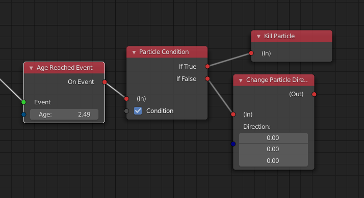
From the video it seems like “kill particle” and “mesh collision event” are to be read in reverse, right-to-left ? (I mean in reverse compared to what I know of node systems so far, not the least of which being Cycles) And then “mesh collision event” pipes into a “particle system” node which I assume is the correct way to read it ? (so left to right ?) All this is a bit confusing…
I kind of agree with @LudvikKoutny here in that it doesn’t seem to leverage all the power of visual programming, ie all this could be done with a fixed interface like the one we’ve had so far with Blender particles (albeit not as elegantly), and most importantly I can’t see clearly the flow of information… (that may be an acquired taste ?)
Right, this picture is outdated. There were problems with this is approach, which is why I changed the design. Also see this.
3 Likes
I have the same mixed feelings as @Hadriscus
I can’t see a clear flow of execution, I see a lot of parallel nodes and it’s not easy to understand what is happening and when is it happening, also the reading direction that it seems to have from right to left is kind if weird.
As @Hadriscus said, it could be something that should be learned, but so far I find it kind of confusing, I may be wrong, but that’s what came to my mind after watching the video.
@jacqueslucke maybe some actual video explaining what has been done up until now, not a short one, but like the session you gave to the people in the studio, could be great to help understand the direction, right now is as confusing as it was some months ago, at least for me.
EDIT: Regarding the right to left… it’s true that it is the same solution as in ICE, but in ICE the final node was some kind of processor with more options, and inside that node you had the full logic of that solver, and that logic was left to right if I recall correctly, the right part being the final result, it could be the same here, and Ic ould be not understanding it, so maybe it just needs an explanation make it work in our heads 
EDIT 2 : Anyways, it’s good to see this progress… I alwasy put the things that seems a bit weird to me and such things, but you are doing a magnificient job @jacqueslucke
@JuanGea I don’t know what you mean exactly with right to left.
In my mortar example above it feels more like left to right. That’s a build from monday.
You set rules (Kill particle for example)-> that goes into and event (Age reached)-> and the result goes into the particle system. Or do I misunderstand you?
2020 will be mindblown, I am sure of it. 
When I say right to left is becasue in a Left to Right system you create the particles and then you start managin it’s behaviour, so the particle system is the first thing created, just like in compositing the first thing you load are the rendered frames and then you start working with them from left to right.
In the current system I see a lot of “loose” node trees that are mixed towards the right, and the particles are in the right part, and you connect some behaviours to it, so you cannot clearly read the flow, there is no flow there, I see a bunch of nodes that are all connected to a single input socket, it’s not possible to read or to understand the flow, when you connect so many nodes to the Influences socket, which influence is executed first? which is the latest one? how do they affect to each particle?
In the case of ICE the solution it had for those situation was an execution order node, it could be the latest node or a middle node, but you had several inputs, and you were able to define the execution order of each one.
That does not mean that I think this is wrong, but I cannot see the flow in the particle behaviour, that’s why a more indeep explanation could be welcome, because this may be a very good way of handling particles, but so far I’ve never saw a system that works like this with particles, not even ICE as I recall it.
I still don’t know how this can handle for example a mutable particle system that starts behaving like a fluid then goes to behave like a rigid body system and then mutates to behave like a granular system, so far the demos I saw are “spawn” demos, but spawning different particles systems are not complex simulations, it’s creating a birth event when some other event happens, the real difficulty with particles is to drive their movement with precission (up to a single particle level if needed, using ID’s or other effectors or groups dynamically created) and to make those particles behaviour mutate in an eased form, so you can actually manipulate particles without having to give birth to new ones, maintaining it’s properties as they are, just making them shift to a different behaviour, and having a secondary particle system that is “pasted” over the original particle systems is not a good solution since it will effectively double your amount of needed particles, if you want to do a granular simulation with let’s say 100 million particles you don’t want to be forced to deal with 200 millions, even if 100 million of those particles are dumb particles.
Thing is that I just don’t understand this way of dealing with particles, again, not saying is wrong, just that a bit more visual clarification to understand this could be welcome, not an indeep tutorial, just an explanation in video of how this systems works, and what’s the idea behind it.
5 Likes
Oooooohhhhhhh I understand. There seems to be a fundamental difference in the way nodes are thought of : it’s not that “kill particle node” is a node taking particles as input and killing them; it’s the “kill particles output” is a variable piping into some particles and setting their state as dead. If I understand correctly ? Is actually still flows from left to right… my brain hurts a bit but I think it makes sense now.
Shouldn’t we work on compiling actual use cases for particles ? I mean typical particle simulations that TDs would have to come up with for a show, or a film ? Shouldn’t we start from there and ensure the functionalities allow these “example” simulations ?
Yes, that could be great, but current functionality is still a bit limited, anyways I think @jacqueslucke has done that and he is working on top of a basis of reference and ideas that came from many places.
In any case, I think a video explaining this a bit mor in detail, and why is it designed that way could be very welcome, because I’m not sure how things are thought, how things should work, how systems should be read, but this is also that has been taken into account, hence the change from left to right to right to left.
Taking ideas form ICE is also great, VERY GREAT, and ICE was super powerful, but when you were learning it it was a bit “quirky” at the beginning until you understood how it actually worked, I suspect this is the same situation, but we need more info to understand the idea below all this
1 Like
Ahh ok, now i got you.
Maybe it is a good idea to make something like a Mindmap or schematic nodetrees/examples in advance, to see if complex situations are possible and still readable. Especially when there are multiple nodetrees combined (hair, particle, modifier, textures, shaders…)
I know this is future stuff, but this could prevent obstacles in the future. I’m pretty sure Jacques already did something like this…
I will get my Houdini files I collected over the years and study the relations between nodetrees and try to bring it down to an easy to read diagramm. When I find the time…
I think because houdini can do almost everything, it’s good to take it as a paragon, BUT make it much more easy in almost every aspect. Same goes for xsi I think, but i never worked with it.
A mini-map in the corner of node editors would be useful no matter what. +1 from me, not that it means much.
2 Likes
For the particle type node (that I would call Particle System), why is there only one input type ? Why not split the only input into different input types (emitters, forces, events…)
1 Like
I agree with Hector, the word “Type” is very ambiguous. Currently, when we want more than one stream of particles from a single emitter you create a new “System”. I know particle nodes is a new thing but it seems more intuitive to me to just stick with the already defined standard language. Also, I’m a native English speaker and System just makes more sense. You can have systems within systems and reference them from other events and so on. In my mind, systems could be a node that encapsulates more complexity.
It’s funny because I can actually read this perfectly. It’s very much like a shader graph. I really like it. I know you have your own ideas about how things should be laid out but I think this graph is much easier to read coming from other graphs in Blender and even in other programs.
1 Like
It took me some time but I got my head around it. It’s declarative in the sense where ‘kill particle’ is an order given to the simulation, just as ‘emit particle’ is also an order. It’s not a data flow graph, it’s an event graph - and suddenly all seems clearer. :o
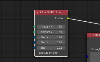
New particle system is very flexible (and huge thanks to author(s) for this), but what is reason for limiting “Initial Grid Emmitter” only X and Y axes? Why it not use axe Z? How i can make 3D grid?
2 Likes
Uff … I just found this thread … I will be posting a new color scheme for the new particles system UI … since there are certain things that don’t seem right … in natural sense of colors.
Red for example is usually used for error/caution/warning type of messages. My whole point is that colors should signify purpose of ‘node categories’.
4 Likes
@jacqueslucke I was thinking, I’ve heard that in the future we may have a workflow where we can create a texture in the shader editor, or maybe a new workspace with the same nodes, then the output of that would be usable for different things within blender. Essentially you could use a homemade texture for brushes, displacement modifier height maps etc, and you could make changes on the fly to the texture and it would update.
This is just conjecture, but if we did get that kind of workflow, I was thinking, wouldn’t it be great if we could attach a texture output from the shader graph into particle nodes as it’s own node. We could use it for vertex groups possibly. How cool would it be to have a 4D noise as, say, a density factor!
I wrote yet another document explaining the core concepts I have in mind. I hope that helps to clear up some confusion.
I know that it can be difficult sometimes to understand how to do the simulation you have in mind, based on these abstract concepts. I recommend that you let it sink in a bit more, and if it is still unclear afterwards, you can ask me again.
If you have questions regarding the concepts in general, please ask.
I’ll not create a video tutorial in which I explain how to use the system anytime soon. That would be out of date rather quickly anyway. If you want to learn it, I recommend you just give it a try or ask other users who successfully created simulations with it already.
17 Likes
@jacqueslucke Read through your high-level overview, it looks great! I am curious though how Influences are going to work and combine together. In a scenario where you have two sets of influences (Influence Tree A and B) influencing (connected to) a particle system node, how do you plan to resolve them in a deterministic way? While the individual influence trees themselves would be deterministic, it wasn’t entirely clear how a solver for those combined influence trees would work. Would Influence Tree A always evaluate before Influence Tree B? How would the end-user know?
From a design standpoint, I think it would make sense if there were individual socket inputs per Influence, or even an expandable/collapsible Influences to truncate the extra sockets.
I think this still fits with your Uber Solver idea. To be clear, the user needs to have control over how Emitters, Events, and Forces are resolved. The end result would be similar to the Modifier system, where we’ll have Interfaces that could be stacked in an ordered/ordinal manner.
1 Like