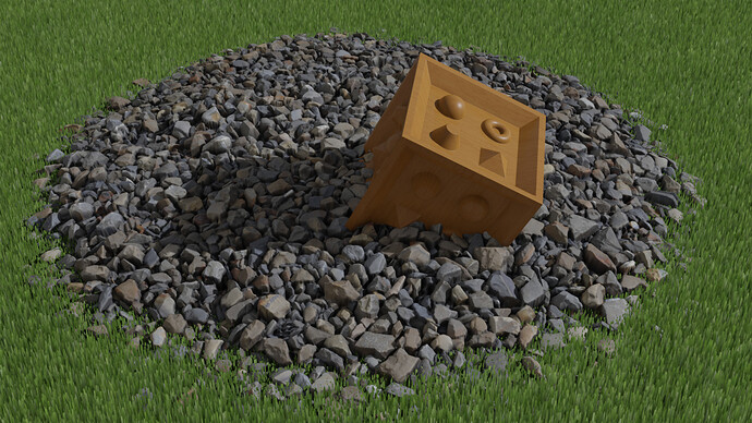
I have completed a first version of an alternative Eevee only implementation that uses the displacement output of the material node tree for parallax occlusion mapping. The code diff and a sample blend file can be found here: https://developer.blender.org/D9792. An experimental build can be found here: GraphicAll — Blender Community
User Interface Integration
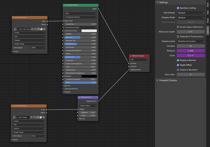
The user interface gets a new combo box in the Eevee material settings that lets the user select either “Bump” (default) or “Parallax Occlusion” as displacement rendering technique. A simple material node tree with displacement output looks like this:
For parallax occlusion mapping only the displacement in the direction of the local normal vector is considered. The “Displacement” node does exactly this, so it is recommended to use this as last node connected the displacement material output.
If “Parallax Occlusion” is selected as Displacement method, additional options and parameters are shown:
-
Samples: Defines the number of linear search steps used for ray marching in the parallax occlusion mapping shader. Higher values give better results, but take longer to complete. The linear search for the height map intersection point uses a randomization to achieve a dithered blend for parts of the geometry that can’t be reliably resolved with the given number of samples
-
Midlevel / Scale: These parameters are basically the same as on the Displacement node and define the displacement search space for the parallax occlusion mapping. If the Height input on the Displacement node is in the [0, 1] range then the exact same values can be used (or copied with a driver as in the sample file). For other ranges the values have to be chosen such that the complete displacement (min/max) is contained within the space described with Midlevel and Scale.
-
Displace Normal: If checked then the normal vector is displaced for the shading operation based on the provided displacement function. Otherwise the original normal vector (for the geometry without displacement) is used for shading.
-
Depth Offset: If checked then depth value of each fragment is offset for shading and shadow mapping operations based on the provided displacement function.
-
Displace Backface: If checked then the parallax occlusion mapping is applied to backfacing parts of the geometry as well. Otherwise backfaces remain flat (no displacement). This option can be useful in preventing rendering artifacts from (wrongly) displaced backfaces.
The displacement node tree can make use of (any combination of) the following inputs for parallax occlusion mapping:
- UV texture coordinate (only the default map is supported)
- Texture Coordinate: Generated
- Texture Coordinate: Object (arbitrary objects as source supported)
- Geometry: Position
- Geometry: Normal
This approach supports both image texture based and procedural displacement functions.
Known Issues and Limitations
-
The known limitations of parallax occlusion mapping still apply. The curvature of the geometry is not correctly represented. The ray-marched volume attached to each triangle is flat and unlimited (beyond the boundaries of each triangle) but only visible “through” each triangle.
-
The displacement node tree is complied into a GLSL function and then evaluated iteratively in the parallax occlusion algorithm. Any overhead or inefficiency in the displacement node tree gets multiplied by the number of iterations.
-
Currently the code always requests (and interpolates) orco coordinates (for supporting “Texture Coordinate: Generated” as input) even when the displacement node tree does not make use of them. This could be optimized by analyzing the displacement node tree first and requesting it only when required.
-
Images Textures used in the displacement node tree are always sampled at the default LOD. For linear interpolation this is a dFdx/dFdy based automatic LOD which can lead to 2x2 pixel blockiness near the visibility contours of displaced geometry. Because of the iterative nature (with divergence) of the texture evaluation in parallax occlusion mapping, this automatic LOD can be wrong or undefined. For cubic interpolation, always texture LOD 0 is used (full resolution). This produces good results, but can impact performance (memory bandwith / cache). This issue is difficult to fix in a general setting. For a displacement node tree ending with an image texture and a displacement node (with constant parameters) one could code an optimized alternative implementation that directly integrates the texture lookup (and LOD selection) into the parallax occlusion iteration code.
-
The internally generated tangents for the “Texture Coordinate: Generated” input are not compensated for the smooth normal vector, which can lead to flat shading like artifacts. This issue is present in the current bump mapping implementation as well. See https://developer.blender.org/T74367 for details. Similar artifacts present with bump mapping when using “Geometry: Position” or “Texture Coordinate: Object” as input are prevented when using the parallax occlusion mapping option. Potentially this partial fix could be “backported” to bump mapping as well.
-
The shading node tree part is evaluated with “Geometry: Position” and “Texture Coordinate: Object” without the displacement in normal direction (the parallax occlusion based offset is still applied). In contrast Cycles evaluates the shading part using a position with the displacement in normal direction applied. The underlying problem is illustrated (using the normal vector as input) in this post: Parallax Occlusion Mapping - #18 by mmoeller. It would be quite easy to make the current implementation produce the same results as Cycles. But in my opinion either the behavior in Cycles should be changed or both values (displaced and undisplaced) should be exposed to the user as input to the shader node tree.
-
The approximation of the displaced normal can no longer (in a general node tree setting) exploit directly the knowledge of the resolution of the heightmap as in the first implementation (see above). This prevents “intelligent” smoothing of texture based displacement functions and forces the use of cubic texture interpolation (everywhere) to get smooth results. This also has some impact on performance.
Again, it would be great if something like this could be integrated into the official release of Blender. Regarding that objective, I’m open for any change requests.

