Parallax Occlusion Mapping

Generated UV coordinates should work with the current implementation as tangents are generated by differentiation. The sand material in the sample blend file uses (simple) generated UVs:

Multiple UVs are difficult, because you need to have height maps for all UVs that produce the same displacement for a given location.

Using a procedural texture (like noise) for POM is also in theory possible with the current algorithm. It does not work with the current implementation, because there is currently no way to provide a function as input/parameter to a node (except by providing it as texture image obviously).

I think the Depth Offset code could also be be hidden from the user and be replaced by a system that only internally creates the depth offset connections to a hidden socket on the BSDF nodes.

For an automatic displacement based system things are more complicated. The only way that I see it could be realized is by compiling the node tree (UV -> Displacement output) into a function that then can be sampled by a (hidden from the user) inserted POM node that connects to all open UV and Normal sockets. This solution would prevent the use of generated UVs. And it would be a lot simpler to realize if there is already support for mapping a (part of a) node tree into a function that then can be used as input to a node.

I have implemented the POM node for Cycles not because I think it is really useful in Cycles, but for completeness. If the node is exposed to the user, it might be useful if it does the same thing on all render systems (at least as far as reasonably possible, that means without depth offset in Cycles).

4 Likes

Had a closer look, i had the kernels in multiple locations due to another diff i was testing earlier yesterday and blender was picking up the stock ones rather than the POM ones, after resetting the configuration all is good!

6 Likes

Right, but I was referring to 3D texture coordinates for noises, not 2D.

Bump mappping through the displacement socket works like this, it automatically replaces the normal, this would automatically replace UV coordinates also.

It would be great if this could replace the barycentric coordinates and have that work for multiple UVs, but I don’t think it will actually work since POM can go beyond the bounds of the triangle and into another one.

Not being able to use generated UV coordinates would indeed be a limitation, that’s a trade-off. It would be good to hear Clément’s opinion on this.

Also not mentioned, but it only works with image textures, not procedural textures. I’m not really sure how procedural textures plugged into the displacement socket would work. So maybe POM as a technique is just not general enough to be exposed as a general displacement method.

It may be useful in some cases, but I want the renderer to be a bit more lean and opinionated about these kinds of things.

There might be a way to support POM from displacement with generated UV (3D texture coordinates). Instead of only (linearly) extrapolating UV in the search direction one could as well extrapolate the position (and normal etc) linearly.

The current code uses something like uv + dFdx(uv) * s.x + dFdy(uv) * s.y as UV coordinate to sample the height map. One could add pos + dFdx(pos) * s.x + dFdy(pos) * s.y as position argument to the height map sampling function. Similar for the normal vector and potentially other arguments.

The displacement function would have to be compiled to a function (uv, position, normal, …) -> displacement. In every step of the POM iteration one would (linearly) reconstruct uv, position, normal (as described above) and feed it to the displacement function. The z-component of the result could be used as height value. Once the height map intersection is found, the resulting (shifted) uv, position and normal (corrected to be normal to the height map) are then connected into the surface node tree as inputs (or even better replace the builtins for the surface shader tree).

In terms of efficiency it depends how good the GLSL to machine code compiler is at removing unused code. For example code that calculates the incremented position in the POM loop while the displacement function really only uses UVs for example.

A solution like this would also enable the use of procedural textures for the height map / displacement function.

Things that would not be supported in this approach:

  • Displacement / height map that is scaled relative to the local UV scaling. For this another Displacement node would have to be created (or the current one modified) to support this “Relative” to UV scaling mode. The current Displacement node only support an “Absolute” mode (either in object or world space scale). But I think this is an independent problem that could be solved if there is enough interest for a “Relative” scaling mode. This could also be interesting to have for situations without POM. The POM node in my current implementation supports this.

  • It might be difficult to distinguish to which part of the surface shader node tree the POM corrections (new UV, new position, new normal, depth offset …) are applied. For example for some parts of the shader it might be interesting to keep the original normal while for other parts the corrected one might be used. Similar for the position / depth offset. For example for a grass POM material you might want to avoid applying the corrected (wrt the height map) normals to each grass strand and use the normal of the original surface instead. With an automated/forced feeding of the POM corrections into everything of the surface shader node tree there might not be enough flexibility. And duplicating the outputs of the Geometry node to have original values and Displacement corrected values for everything might also be confusing for the user. With a manually placed POM node the user can choose where to use the corrected results and where to use the original ones.

I have looked at the Eevee code and the main difficulty (at least for me) seems to be the compilation of the Displacement node tree into a separate GLSL function that could be called in a POM code. The whole GLSL gpu codegen implementation seems to be based on the concept of having one single node tree and compiling this into GLSL. Without changing this concept, the POM iteration would have to be completely unrolled (with a copy of the Displacement node tree for every iteration), which of course is not a good idea for higher iteration counts. In my current implementation I have avoided this problem by basically assuming that the Displacement node tree is just one single Image texture node, configured directly on the POM node.

I fear that changing the gpu codegen implementation to support the compilation of several node trees into several GLSL functions, which then can call each other is beyond the scope of what I could realize myself. And I’m not sure if it is really a good idea to implement this (as POM specific code) into the GLSL code generator.

Related to this is the question if such a functionality should not be exposed to the users as well. That means supporting functions (with arbitrary signature or at least float->float, float->float3, float3->float, float3->float3) as socket type in the node tree. A texture map could then be a node with just one output socket of type function(float3->float3). This could for example be connected to a blur node with an input and output of function(float3->float3) and some parameters.With a way to let users define such functions (with something similar to current node groups) as node tree, the POM implementation would then become quite simple: Similar to the current bump implementation, the Displacement node tree would have to get transformed and inserted as copy into the Surface node tree. The resulting tree could then be consumed again by the GLSL code generator without having any POM specific code in the code generator.

5 Likes

Using displacement output has serious side effects, doesn’t it? It means that parallax mapping would happen at a particular time in the node tree evaluation, which would limit what users could do with inputs into it. Which is both unnecessary and very far from immediately obvious.

Default UV values, like default normals from bump mapped displacement output, are nice, but there are much cleaner, more intuitive, and more general interfaces imaginable than trying to stick things that create defaults into material output. Default normals being specified on material output is kind of backwards, and it’d be the same for trying to specify default UV via material output.

Unrelatedly, it seems to me that the main reason that POM is something that would have to built into Blender is because there’s no ddx/ddy node. (At least, with regards to Eevee.) If there was a ddx/ddy, POM would be a file on Blendswap or a tutorial on Youtube, right? Albeit, with some fixed number of iterations, or as a scipt that generated a fixed iteration node group. And ddx/ddy is useful for more than just POM. Is there some reason that it would be impossible to expose ddx/ddy to nodes? If not, that would be the more powerful, more elegant thing to do.

1 Like

I think ideally the node tree creating the displacement output should be completely separated from the node tree creating the surface shading output. For several reasons:

  • The input nodes for the displacement node tree should be limited to types that make sense in that setting. That is things like position, normal, uv, true normal. Other inputs like light path or ambient occlusion inputs don’t make much sense for a displacement node tree setup.

  • It would allow for a separation of what for example the “position” input is: For the displacement node it is the original not displaced position, while for the shading node tree it would be the actual (displaced) position. For the shading node tree one could also (for example for the normal) expose both, original and displaced variants as input. But the default would be the displaced ones.

  • It would simplify understanding the user interface by making it clear that the displacement tree is applied (separately) first and then the shading tree is executed on the displaced geometry.

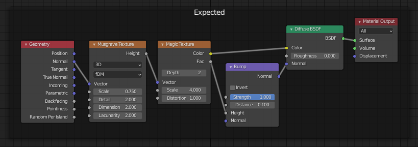
An example where the current mixture of both node trees (shading and displacement) gets really confusing:


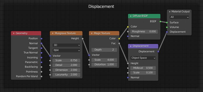
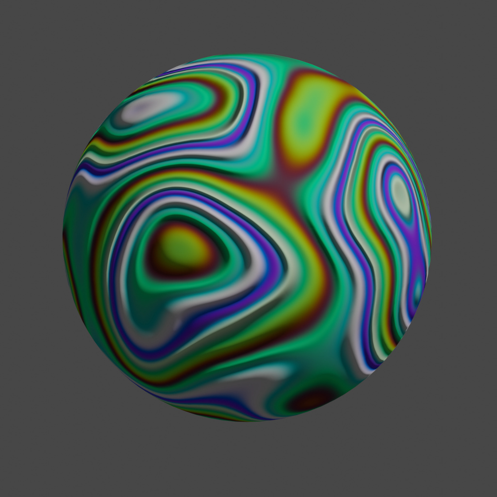
This is a simple setup that creates color and displacement waves based on the current normal of the geometry. Because the Color and Height come out of the same Magic Texture instance, one would intuitively expect the bumps and the color bands to be aligned. Intuitively I would have expected something like this as result:


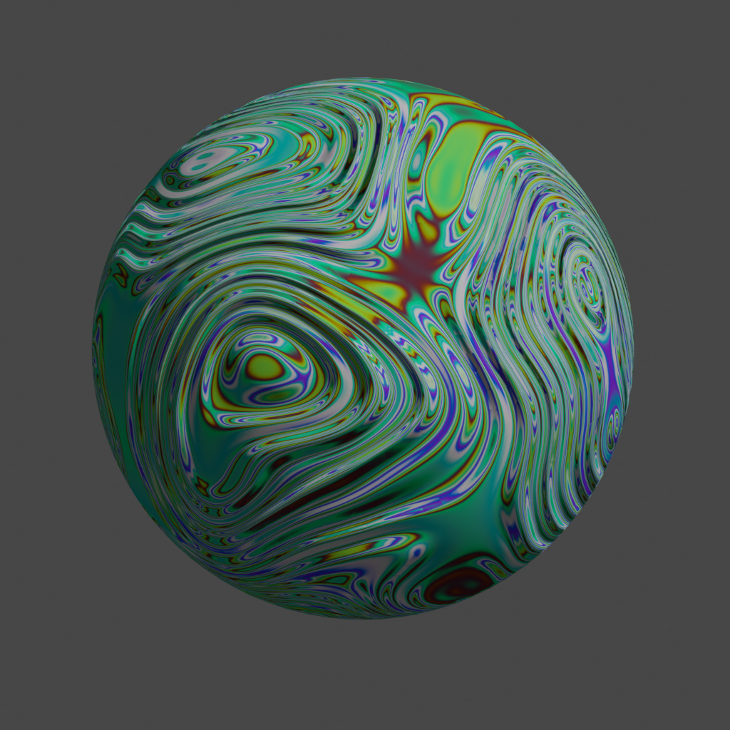
But what you actually get from the above node tree is the following:


Internally the above node tree gets converted to something like


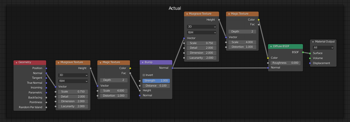
which produces the same rendered image as the displacement node setup (in Eevee). Note that now there are suddenly two instances of the Magic Texture block with different inputs and one creates the Color and the other the Height for the bump mapping. This also explains why we get color bands with a different frequency compared to the bump bands.

The first rendered image above (what I would have expected as output) has been generated with the following (manually created) node tree:


Here the bumps and color bands are generated from one single instance of the Magic Texture node and the color and bump bands are aligned.

With the automatic bump mapping this problem occurs when the (default) normal input is used in the displacement node tree. By adding an automatic parallax occlusion mapping generated from the displacement node tree, I would expect that things can get even more confusing for example when the position input gets used in the displacement node tree and the shading node tree, which is not so uncommon for procedural materials. For the shading node tree one might want to use the displaced position (for example when checking for light visibility and similar things), but for other operations (procedural coloring) one might want to use the shifted original (POM shifted but not displaced) position as input to get colors that are aligned with the procedurally (from original position) generated displacements.

Maybe there is some good reason for having both node trees (displacement and shading) combined into one that I’m missing?

Still I think that an implementation of parallax occlusion mapping based on a displacement node tree has some advantages. It would allow to specify the height map with a (more complex) node tree instead of a single texture. This could also be achieved with a user exposed POM node type and a (still missing) system of node sockets/connections of type function and a way to define them with a node tree. Beside this, a displacement node tree based solution (which limits POM effects to one single instance) might also help when trying to add support for shell mapping Interactive Smooth and Curved Shell Mapping. Shell mapping would require the generation of shell geometry, which might be simpler to integrate in the user interface if it is a per material setup instead of a per node. Obviously you can’t generate shell geometry for every POM node used in a material.

I have looked into compiling the displacement node tree into a separate GLSL function inside the Eevee codegen (this would be required by the “auto-magical” solution), but without much success so far. Obviously there are solutions, but I would prefer a solution that does not require a rewrite of large parts of the existing GLSL code generator.

Regarding missing parts for a soft implementation of POM as node tree: It would require the following:

  • Some new ddx/ddy node or alternatively some kind of on-the-fly tangent base generating node (that basically outputs the relevant parts generated in the POM code using ddx/ddy). Issues with a ddx/ddy node are the limitations associated with how these values are calculated (2x2 pixel block, derivative approximation is non-symmetric and alternating). Supporting it in Cycles (on arbitrary input) requires node tree duplication, which can be expensive (but it is the same problem for the current Cycles POM code). Exposing (and supporting long term) such low level operations might be against Blender node tree design principles. Chained use of ddx/ddy (for higher derivative) might not work (in GLSL) or at least produce unexpected results.

  • Some pixel depth offset support for actually modifying the depth result of the fragment that gets written/compared to the depth buffer. As outlined in the first post, this might also have other applications (blending), but can’t really be supported in Cycles. It would also need some integration into the BSDF nodes in order to affect lighting.

  • Some kind of iterations support in the node tree. Currently implementing POM in the node tree basically requires completely unrolling the iteration loop. For higher iteration counts this can produce long shader codes (takes long to compile and might not be ideal for execution). Ideally the iteration support also allows for conditionally aborting the iteration (for performance reasons).

  • Some way of control for selecting the mipmap level when sampling the height map texture. The automatic ddx/ddy based mipmap selection does not work very well when iterating the UV in POM. The result is that a too high resolution mipmap level gets sampled during iteration and performance becomes really bad (for higher resolution height maps).

  • Ideally some way to change the height map in a POM node setup (provide it as parameter) without the need to manually open the node group and replace the right part inside it.

If you only use (scaled) world coordinates as UV, you can get away without ddx/ddy parts. If a uv map is used where U and V are (mostly) orthogonal, you can get good enough tangent vectors from the Normal Map node (with constant colors as input), so also in this case you can get away without ddx/ddy. At least in Eevee. In Cycles, the Normal Map node produces “corrected” normals, which are basically just wrong, so not suitable for generating tangents. I started with creating a node tree setup for POM, but the limitations are annoying. That’s why I have written the code to try an implement it directly into Blender.

5 Likes

Thanks for the extra info on it. Checking out papers on POM atm, something to learn :slight_smile: Didn’t realize they needed to write to Z buffer.

Sure, but those exist in any implementation of POM, right?

If there is some kind of principle like that, I’d wonder why we have parametric coordinates, which are far less useful than screen space derivatives would be, and just as low level…

Would be another thing that would be nice for Blender to support, although a scripted solution can handle it by miximg between script-generated manual mipmaps. Well, for linear filtering at least. Yes, it does impact performance.

Again, something it’d be nice for Blender to support in a more intuitive fashion, but the way I’ve worked around this in the past is via linked node groups containing only an image texture node. Edit the image texture node in one group, edit in all of them.

edit: After checking out A Closer Look At Parallax Occlusion Mapping - Graphics and GPU Programming - Tutorials - GameDev.net , I see-- you don’t literally need to write to the Z-buffer, but you need your shadow buffers and comparisons to be aware of the POM (eevee), and there isn’t really any kind of interface for interacting with those at this time.

1 Like

The ddx/ddy functions are not strictly required for POM. If you have some other methods for obtaining suitable tangents (constant vectors for wolds space projected UV, interpolated from tangents included in the vertex data, …) then you can use those. The ddx/ddy approach is just a nice way of generating correct tangents directly in the fragment shader for arbitrary UV parameterizations and without any preprocessing.

If ddx/ddy is used only internally (as in the current Bump node of Eevee or perhaps in a future POM node) you might be able to handle/hide the limitations of these functions for this specific application. If you expose them for arbitrary use as a new node, you would have make the user aware of its limitations (some of which might even be hardware dependent).

I think it would be very easy to write a patch for adding a ddx/ddy node (at least for Eevee, but it might be possible as well for Cycles) if this is something the Blender developers would like to include.

Of course one can implement POM without PDO support. But the resulting effect is even more difficult to use, because it gets very difficult to hide the boundaries of the POM effect. With standard POM you can see into the displacement layer far beyond the limits of the original base geometry (grazing angles).

And example render from the provided POM sample file when using the sand and rock material: For POM without PDO you get:


The same geometry with POM and Pixel Depth Offset:

29 Likes

What a BIG difference, I hope PDO can be implemented in Cycles too :slight_smile:

3 Likes

This feature would be a godsend for me. It would make so many scenes infinitely easier to create and render. In both Eevee and Cycles!

I know we can achieve this result more or less using micro displacement but the sheer amount of geometry that generates is insane, often resulting in tens of millions of polygons (depending on image resolution) consumes a lot of memory on the GPU, and it brings with it very long generation processing times that need to be computed every frame. It’s really not ideal for something like sand on a beach.

This in comparison could generate the exact same effect in many situations with nothing more than a low poly shape and with no time spent generating geometry, consuming much less memory in the process. From an artistry point of view it would also be significantly easier to work with since it would be material based and you wouldn’t need to add modifiers and whatnot to achieve the desired outcome.

I really hope this makes it into Blender for both Eevee and Cycles. It would be much easier to work with than microdisplacement.

12 Likes

This is amazing and the development team should implement it in blender right away.
Here’s a little experiment I did with POM

without POM

with POM

11 Likes

I agree, but we need it also for cycles, it would relieve a LOT of the displacement limitations :slight_smile:

12 Likes

I think I found a (simple enough) way to compile the displacement node tree into a GLSL function for Eeevee that can be sampled iteratively for POM. I’m now trying to complete this into an implementation without user exposed POM or Depth Offset nodes.

From what I see so far, I will have to add the following settings to the material (Eevee only):

  • Displacement Type: {Bump, POM}

For POM:

  • Samples: integer: Number of POM linear search steps
  • Min Displacement: float
  • Max Displacement: float
  • Depth Offset: bool: To enable (or disable) depth offset effects
  • Modify Normal: bool: To enable (or disable) replacing the default normals in the shader node tree.

The user provided min/max displacement parameter is required to define the space in which the search for the displaced surface is done. It is difficult to determine the possible min/max displacement by static analysis of the user provided displacement node tree. If this space is chosen too large (by the user) some of the Samples steps are wasted, if it is too small, the displacement will be “clamped”. An alternative could be to specify Midlevel/Scale instead of Min/Max (Min = -Midlevel * Scale, Max = Scale - Midlevel * Scale), but this might be not very intuitive when the displacement node tree does not use a (height input clamped) Displacement node as output.

Other potential problems of a purely displacement based implementation:

  • The displacement node tree can become quickly “expensive” to evaluate (iteratively). For two reasons: Because the user adds too many operations or because the code generation in GLSL does not manage to completely eliminate “unused” optional operations (like perhaps per node texture mappings or similar).

  • In the basic implementation there will be no way for the code to specify mipmap levels for the image textures used in the displacement node tree. This results generally in things like a heightmap texture getting sampled at too high resolution (because ddx/ddy fails on iterated uv), which degrades cache/memory performance on the GPU.
    It might be possible to detect the case where the user adds only an image texture node followed by a displacement node for the displacement node tree. In this case instead of adding (internally) a POM node based on sampling a generic compiled displacement GLSL function, a POM node with a texture parameter could be added (basically like the implementation in the first post, but automatically generated). Like this at least for the functionality provided by the original implementation, the same performance could be maintained.

  • The “Relative” displacement scale mode will be removed from the implementation. In any case, it does not really work well with POM in generic cases. It works well only if there is no strong gradient in the texture scaling along the geometry surface. That means you need to have constant texture scaling on each individual part of your geometry. There are use cases where the relative mode could be useful. But this would have to be added to the Displacement node anyway, so I will currently remove it as objective.

In this new implementation (without new user exposed node types) I will completely drop the support for Cycles as there will be no need to support it “just for completeness”. Also the Depth Offset based material blending will be dropped (this could be added separately if there is any interest).

The main advantages of this implementation will be (hopefully) support for (some) proceduraly generated height maps. No new node types are introduced, so this will just be an (optional) setting for how to make use of a user provided displacement function during rendering (in Eevee), like the current Bump effect.

Regarding the discussion of whether or not node types for ddx/ddy, depth offset or POM should be exposed to the user: I think it depends on the long term objective/design of the shader node tree. Should it be a renderer independent description/model of the shading and displacement properties of a surface (which then is rendered as good as possible on any given platform)? Or should it be a way to expose all techniques/features of every renderer platforms in a user friendly (non programmer) way. The first approach (if followed strictly) will mostly limit support to techniques for which there is a good way to implement them on all rendering platforms, while keeping the node tree relative well separated from the implementation. The second approach will tightly couple the shader node tree design to the supported rendering platforms, but at the same time provide support for more techniques.

11 Likes

Hello, first time in this channel.

I understand that the POM is something tricky to integrate with the existing tools. Also, I do not understand why not considering Cycles ( I do not want to ask again for Cycles support ). This is a feature coming from the gaming industry and it is a regular progression for eevee to have it. But why not Cycles ? IMHO, the cycles engine is made to be the realistic render engine, and can also include a such functionality. I saw on forums (blenderartist_POM_old_discuss) that it is hard to make with GPU. But, it is the unique limitation ?

Anyway, thanks to work on it, I’m waiting this feature for long time now.

1 Like

Hi Kdaf,

Brecht had answer this on 14 october… If you had miss it :slight_smile:

Mmmh I’ll just say that unless there is a better alternative, other engines like FStorm or Corona AFAIK are using this, the Corona 2.5D is based on this I suspect, and the same for the FStorm feature (that I don’t remember the name).

BTW I’m not saying adaptive subdivision and displacement don’t need improvement, because they need it, a lot, we cannot use it in practically any scene, since it does not work for instanced geometry for example, and it’s not adaptive inside the same mesh, just at object level, so for example a wall of stone is not truly adaptive, only if it’s separated in several segments and those segments will be adaptively subdivided, and apart from that, it loads the ram so much that in the end we cannot use it because in a medium scene it will max out the gpu memory.

So far I don’t think all that is going to be improved in at least 3 or 4 years, because there is a super big list of things to improve with cycles, and it’s being filled step by step but having a developer that actually wants to make an improvement like this one, may need some guidance, and even could be good to “isolate” the improvement to make it more manageable and look for something more in the middle ground, but it’s a very welcome improvement from a user perspective, and we users need improvements :wink:

6 Likes

I’m totally with you, I think that the POM is important. Even if someone improve the Adaptive Subd, I don’t think it can be better than the POM ( in terms of performance ). But, I think Bretch have others reason to say that; and I really would like to understand.

3 Likes

There is a difference between POM and a POM-like algorithm adapted to ray tracing. What I don’t think is suitable for Cycles is standard POM as used in game engines.

9 Likes

Ah! Totally agree with that, that’s why I mentioned a middle ground solution :slight_smile:

2 Likes

A POM-like algorithm?

You have my attention sir! Do you have something in mind?

1 Like