Parallax Occlusion Mapping

There has been interest in supporting parallax occlusion mapping (POM) in Blender for some time. See for example https://developer.blender.org/T68477, https://blender.community/c/rightclickselect/t9bbbc/ and Parralax occlusion Mapping in development?.


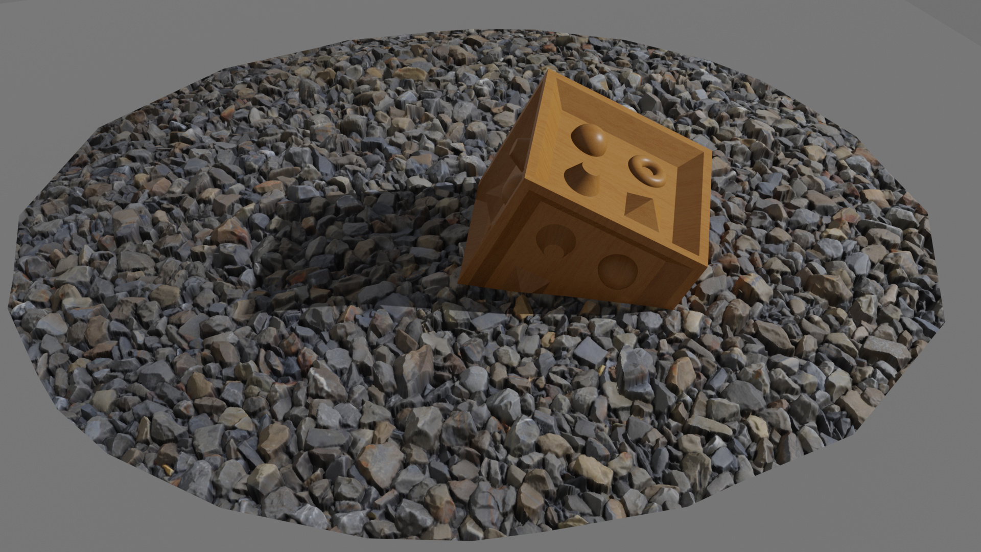
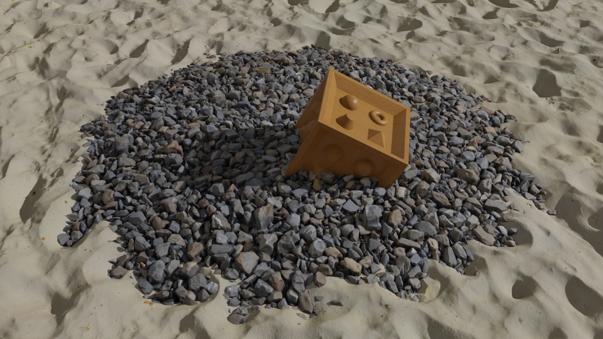
I have developed code that adds a new shader node type “Parallax Occlusion Map”, a new input socket “Depth Offset” to the Principled BSDF shader node and a new shader node type “Depth Offset”. The Depth Offset shader node and input socket are used to implement Pixel Depth Offset (PDO) support in Eevee. The above image shows an example rendered with this implementation.

Parallax Occlusion Map shader node

The Parallax Occlusion Map shader node maps UV texture coordinates from input values to values corrected by the parallax occlusion map. The node is implemented for Eevee and Cycles (SVM and OSL).

The node links an image that is used as height map. For the height map, some of the common properties like the extension mode and color space are exposed. For 16-bit height maps, also the option to disable the half float precision (effectively limiting to 10-bit) optimization is exposed.

The “Samples” property defines the number of linear search samples that are used along the view ray from the top of the height map to the bottom. Internally it uses an additional (fixed) 8 samples of binary search to find the intersection with the height map.

There is a property to configure the “Scale” of the height map to be either in absolute world units (“Absolute” option) or relative (“Relative” option) to the dimensions of the texture.

The “Vector” input socket defines UV coordinates that are used to map the height map onto the actual geometry. If the socket is left open it will automatically pick up the default UV coordinates (like the Images Texture shader node).

The “Midlevel” and “Scale” input socket behave the same way as for the “Displacement” shader node in the case of an “Absolute” scale mode. The “Midlevel” is the height (as value between 0 and 1) that will be placed at the location of the original surface.

The “Vector” output socket provides the UV coordinates where the view ray intersects the height map (the first two components) and the height (as value between 0 and 1) at which it is intersected (third component).

The “Depth Offset” output socket provides the distance from the surface of the original geometry to the point where the height map is intersected, projected onto the view direction vector.

The “Normal” output socket provides a new (world space) normal, that is normal to the height map at the intersection point.

The POM node accepts an arbitrary UV parameterization of the surface as input, the required tangent vectors are generated “on the fly” internally using derivatives (dFdx/dFdy in Eevee and nodetree duplication in Cycles). The implementation is based on Surface Gradient Based Bump Mapping Framework.

The linear search for the height map intersection point uses a randomization to achieve a dithered blend for parts of the geometry that can’t be reliably resolved with the given number of samples (Samples property). The number of samples is not adapted based on view direction (as in some implementations of POM) in order to avoid a strong view dependency of search/sampling artifacts (moving layers).

The height map image is linked in the node itself, because Blender does not support the concept of sockets/links of type texture or function (mapping a vector to a vector for example). The POM algorithm needs to sample the height map (function) many times, so it seems not practicable to duplicate an input node tree many times like in the approach used for the bump map node (only two additional input node tree clones are required). Unfortunately, the internally linked image for the height map prevents the use of procedural approaches for generating the height map.

The usual limitations of parallax occlusion mapping are present here as well. The mapping is correct only for flat geometry. For curved geometry, it still “attaches” a flat volume with the height map at each point and the visible intersection point is traced through this non-curved volume.
The code does currently not implement other algorithms like Prism Parallax Occlusion Mapping or Interactive Smooth and Curved Shell Mapping that require the generation of shell geometry.

Depth Offset input socket to the Principled BSDF node

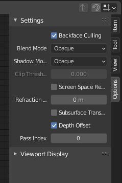
The value provided to this input is used to offset the position of the shaded point along the view ray before evaluating light visibility. It is also used to offset the final depth buffer value (geometry visibility). The actual value provided to this input is the offset vector projected onto the view direction. It can be directly connected to the output of the POM node. This input has an effect only in Eevee, and only when the “Depth Offset” material option is enabled.

depth-offset-option

Depth Offset shader node

The Depth Offset shader node can be used to apply only a pixel depth offset (PDO), but without affecting the shading of a fragment. The Depth Offset shader node is implemented in Eevee only, in Cycles it is a simple feed-through for the BSDF signal.

The value for the “Offset” input socket is the same as for the POM node Depth Offset output socket and the Principled BSDF node Depth Offset input socket.

depth-offset
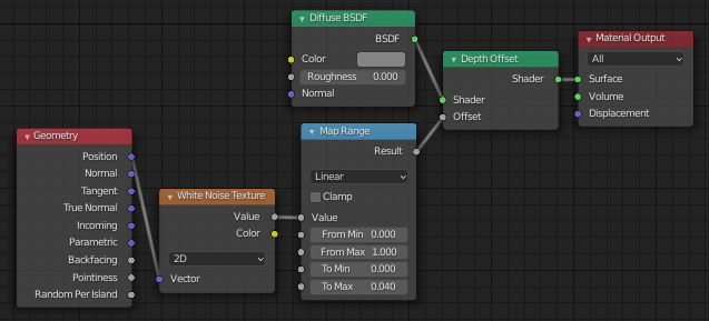
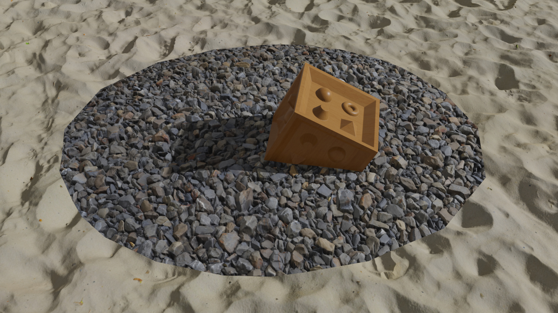
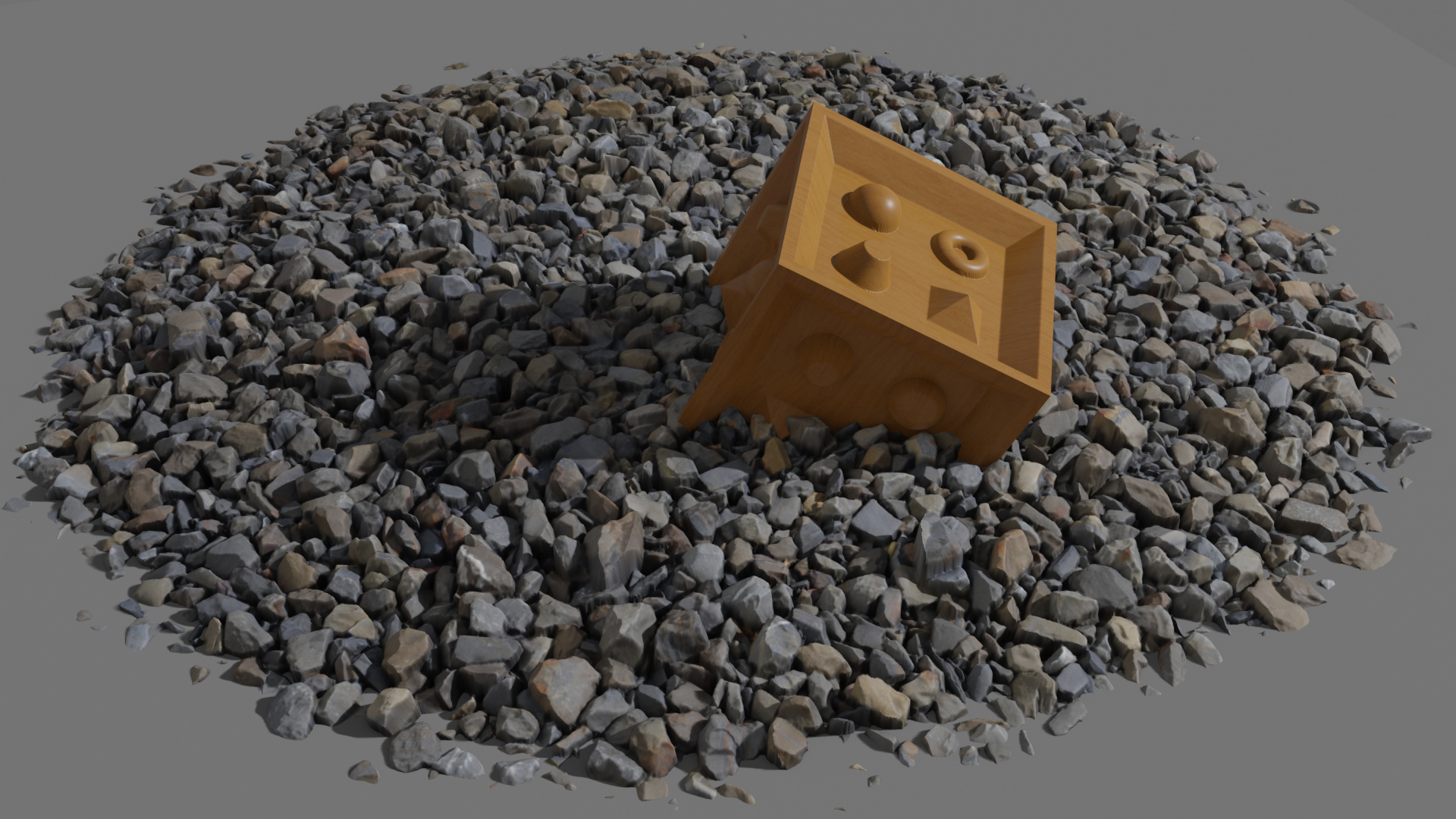
Beside the use of the Depth Offset node in combination with POM, it can also be used for some simple depth buffer based geometry blending (using dithering). A sample setup using a white noise texture is shown in the above image. The following image uses POM with Depth Offset on the sand geometry (flat quad as geometry) and a randomized Depth Offset node on the rock to blend between the sand and the rock geometry.

I have uploaded the diff file of the code based on Blender master commit e5a572157d8cd5947a0b4b7420e728d57d6965ff here: https://developer.blender.org/D9198
On the above page there is as well an example .blend file that shows how the new nodes can be used.

A build for windows can be found here: https://blender.community/c/graphicall/sqbbbc/

It would be great if something like this could be integrated into the official release of Blender. Regarding that objective, I’m open for any change requests.

97 Likes

I’m pretty sure it’d be best to keep the consistency in the UI.
I’m talking about bringing the POM as a displacement type instead of the separate node, and bring the parallax settings under the displacement type.
So that when microdisplacement will become supported in Eevee, there will be 4 choises to displace the mesh, and one of them is POM, and Eevee and Cycles will be interchangeable in terms of displacement.

6 Likes

In cycles I read that this is implemented in SVM and OSL, does it correctly works with both CPU and GPU?

1 Like

As far as this looks promising I have to agree that for consistency I wouldn’t use a separate node just for displacement in Eevee.
Is there a better more consistent way of doing the displacement in Eevee without introducing new nodes/sockets ? Or is it just that because of how the system works?
Great work by the way.

4 Likes

Gave it a quick whirl, OpenCL/Cuda/Optix all render black so it seems to need a little work in that department.

1 Like

I’m going to test it right away, but it’s a good start :slight_smile:

EDIT: Too bad… I cannot test it against today’s master XP
I’ll wait a bit until it’s updated to master, I can’t update it now :slight_smile:

2 Likes

From a user perspective I have to agree that there is some interest in implementing things “auto-magically” from the displacement socket. But the result is not for all cases what the user expects, because some guesswork has to be done for transforming the shader tree in order to add the displacement effect. And the guesswork is not guaranteed to be what a user expects.

For bump mapping things are a bit simpler for two reasons:

(1) The height map has to be evaluated only at 3 points (two derivatives are required), which is realized by duplicating and modifying the given displacement node tree. So the displacement (and it’s derivatives) has to be known only at the current location. For parallax occlusion mapping the height map has to be evaluated at many points, also at points further away. This could get complicated because of the “many points” (static tree duplication seems not feasible) and because of the “further away” (derivative tricks do not work for this).

(2) And the second issue is the feedback of the effect information into the existing node tree. For bump mapping the value has to be fed to unconnected normal input sockets. This is possible most of the time because pure procedural normal generation is rare (except for texture normal maps). So most normal input sockets are either unconnected or go back to the normal output socket of the Geometry node (because they just modify the existing normal). For parallax occlusion mapping, the right UV input socket would have to be found to insert the modified UV there. This is quite difficult if there are multiple UV sets or proceduraly generated UVs.

So if we can find a solution that is always producing what the user expects and covers most use cases, then an “auto-magical” only solution would be ok. If the “auto-magical” system fails for some situations or use cases, then an option to define explicitly what you want with user placed/connected nodes is a must have in my opinion.

Also in the current Blender code the Bump and Normal Map node are exposed to the user for direct use and not hidden for internal use only in transformed displacement node trees. I think we should do the same with the Parallax Occlusion Map.

All the effects that require Depth Offset work only in Eevee. In Cycles the effect of Depth Offset is just hidden. The Parallax Occlusion Map Node itself should work in Eevee and in Cycles (CPU, GPU Cuda, GPU Optix). This is what I get with GPU Optix (on Windows 10 and GeForce RTX 2070 Super):


Obviously the Depth Offset based intersection of the stones with the plane is missing. And also the shadow of the cube gets projected onto the “undisplaced” surface of the stones. The cube is missing selfshadowing (and other effects) on the displaced features (again because there is no Depth Offset).

3 Likes

It’s given me identical results on all gpu backends on my gtx1660

I’m not sure if line 129/130 in svm_pom.h does what it should on all systems:

const TextureInfo &info = kernel_tex_fetch(__texture_info, id);
float radius = 1.0f / fmaxf(info.width, info.height);

It should get the size (in texture coordinates) of one pixel on the height map for sampling the derivatives. The equivalent code worked in OSL until I packed the textures into the .blend file. After that the gettextureinfo function refused to return anything. For OSL I changed the code to pass the radius as parameter instead of trying to get it in the shader code. I think I could do the same for SVM.

It would be helpful if someone with a better understanding of the SVM system could comment on this.

Of course the problem could also be something completely different.

Super interesting.

A way to “avoid” the lack of Depth Offset could be to be able to mix both, displacement and parallax in a way that displacement is only applied in the “edges” of the geometry, with that I mean in the edges from the camera, it could be possible using adaptive displacement, it would be not as light weight as just the parallax effect, but can save a lot of memory for displacement.

Also, do you think the shadow over original geometry only can be solved somehow?

Amazing job :slight_smile:

Have not taken a closer look, but debug build renders black, release works with at least cuda (did not test the others) so if i had to guess it’s probably an uninitialized variable somewhere.

I think it would be best if this could be integrated with the existing displacement system somehow. A design principle in the shading nodes we try to follow is to keep the specific render algorithm separate from the description of the surface shading as much as possible, and we only make exceptions when there is no way around it. It also makes material interchange easier if things are decoupled, both between Cycles and Eevee and other applications.

The problem is indeed that with standard POM you can really only use a single UV map as a texture coordinate, anything else like multiple UV maps or generated coordinates do not work. If they could be made to work that would be ideal, but I’m not sure how it would be done exactly.

If that limitation remains, it becomes a matter of UI/UX design. Both with and without a POM node the fact that e.g. a Noise Texture node will not work correctly by default will not be obvious to users, and you have to read the docs to understand it. Having to wire the UV output of the POM node to texture nodes makes it a bit more explicit, but is also inconvenient. I don’t know immediately how we could communicate this well in the shader node interface directly with or without a POM node.

I don’t think this should be implemented in Cycles. It’s not a technique that’s great for path tracing, and it complicates the Cycles kernel. Especially when it comes to further improvements like better shadows or shell geometry, it’s not a direction I want to go in, but rather focus on improving the adaptive subdivision and displacement system rather than adopting game engine techniques.

12 Likes

Generated UV coordinates should work with the current implementation as tangents are generated by differentiation. The sand material in the sample blend file uses (simple) generated UVs:

Multiple UVs are difficult, because you need to have height maps for all UVs that produce the same displacement for a given location.

Using a procedural texture (like noise) for POM is also in theory possible with the current algorithm. It does not work with the current implementation, because there is currently no way to provide a function as input/parameter to a node (except by providing it as texture image obviously).

I think the Depth Offset code could also be be hidden from the user and be replaced by a system that only internally creates the depth offset connections to a hidden socket on the BSDF nodes.

For an automatic displacement based system things are more complicated. The only way that I see it could be realized is by compiling the node tree (UV -> Displacement output) into a function that then can be sampled by a (hidden from the user) inserted POM node that connects to all open UV and Normal sockets. This solution would prevent the use of generated UVs. And it would be a lot simpler to realize if there is already support for mapping a (part of a) node tree into a function that then can be used as input to a node.

I have implemented the POM node for Cycles not because I think it is really useful in Cycles, but for completeness. If the node is exposed to the user, it might be useful if it does the same thing on all render systems (at least as far as reasonably possible, that means without depth offset in Cycles).

4 Likes

Had a closer look, i had the kernels in multiple locations due to another diff i was testing earlier yesterday and blender was picking up the stock ones rather than the POM ones, after resetting the configuration all is good!

6 Likes

Right, but I was referring to 3D texture coordinates for noises, not 2D.

Bump mappping through the displacement socket works like this, it automatically replaces the normal, this would automatically replace UV coordinates also.

It would be great if this could replace the barycentric coordinates and have that work for multiple UVs, but I don’t think it will actually work since POM can go beyond the bounds of the triangle and into another one.

Not being able to use generated UV coordinates would indeed be a limitation, that’s a trade-off. It would be good to hear Clément’s opinion on this.

Also not mentioned, but it only works with image textures, not procedural textures. I’m not really sure how procedural textures plugged into the displacement socket would work. So maybe POM as a technique is just not general enough to be exposed as a general displacement method.

It may be useful in some cases, but I want the renderer to be a bit more lean and opinionated about these kinds of things.

There might be a way to support POM from displacement with generated UV (3D texture coordinates). Instead of only (linearly) extrapolating UV in the search direction one could as well extrapolate the position (and normal etc) linearly.

The current code uses something like uv + dFdx(uv) * s.x + dFdy(uv) * s.y as UV coordinate to sample the height map. One could add pos + dFdx(pos) * s.x + dFdy(pos) * s.y as position argument to the height map sampling function. Similar for the normal vector and potentially other arguments.

The displacement function would have to be compiled to a function (uv, position, normal, …) -> displacement. In every step of the POM iteration one would (linearly) reconstruct uv, position, normal (as described above) and feed it to the displacement function. The z-component of the result could be used as height value. Once the height map intersection is found, the resulting (shifted) uv, position and normal (corrected to be normal to the height map) are then connected into the surface node tree as inputs (or even better replace the builtins for the surface shader tree).

In terms of efficiency it depends how good the GLSL to machine code compiler is at removing unused code. For example code that calculates the incremented position in the POM loop while the displacement function really only uses UVs for example.

A solution like this would also enable the use of procedural textures for the height map / displacement function.

Things that would not be supported in this approach:

  • Displacement / height map that is scaled relative to the local UV scaling. For this another Displacement node would have to be created (or the current one modified) to support this “Relative” to UV scaling mode. The current Displacement node only support an “Absolute” mode (either in object or world space scale). But I think this is an independent problem that could be solved if there is enough interest for a “Relative” scaling mode. This could also be interesting to have for situations without POM. The POM node in my current implementation supports this.

  • It might be difficult to distinguish to which part of the surface shader node tree the POM corrections (new UV, new position, new normal, depth offset …) are applied. For example for some parts of the shader it might be interesting to keep the original normal while for other parts the corrected one might be used. Similar for the position / depth offset. For example for a grass POM material you might want to avoid applying the corrected (wrt the height map) normals to each grass strand and use the normal of the original surface instead. With an automated/forced feeding of the POM corrections into everything of the surface shader node tree there might not be enough flexibility. And duplicating the outputs of the Geometry node to have original values and Displacement corrected values for everything might also be confusing for the user. With a manually placed POM node the user can choose where to use the corrected results and where to use the original ones.

I have looked at the Eevee code and the main difficulty (at least for me) seems to be the compilation of the Displacement node tree into a separate GLSL function that could be called in a POM code. The whole GLSL gpu codegen implementation seems to be based on the concept of having one single node tree and compiling this into GLSL. Without changing this concept, the POM iteration would have to be completely unrolled (with a copy of the Displacement node tree for every iteration), which of course is not a good idea for higher iteration counts. In my current implementation I have avoided this problem by basically assuming that the Displacement node tree is just one single Image texture node, configured directly on the POM node.

I fear that changing the gpu codegen implementation to support the compilation of several node trees into several GLSL functions, which then can call each other is beyond the scope of what I could realize myself. And I’m not sure if it is really a good idea to implement this (as POM specific code) into the GLSL code generator.

Related to this is the question if such a functionality should not be exposed to the users as well. That means supporting functions (with arbitrary signature or at least float->float, float->float3, float3->float, float3->float3) as socket type in the node tree. A texture map could then be a node with just one output socket of type function(float3->float3). This could for example be connected to a blur node with an input and output of function(float3->float3) and some parameters.With a way to let users define such functions (with something similar to current node groups) as node tree, the POM implementation would then become quite simple: Similar to the current bump implementation, the Displacement node tree would have to get transformed and inserted as copy into the Surface node tree. The resulting tree could then be consumed again by the GLSL code generator without having any POM specific code in the code generator.

5 Likes

Using displacement output has serious side effects, doesn’t it? It means that parallax mapping would happen at a particular time in the node tree evaluation, which would limit what users could do with inputs into it. Which is both unnecessary and very far from immediately obvious.

Default UV values, like default normals from bump mapped displacement output, are nice, but there are much cleaner, more intuitive, and more general interfaces imaginable than trying to stick things that create defaults into material output. Default normals being specified on material output is kind of backwards, and it’d be the same for trying to specify default UV via material output.

Unrelatedly, it seems to me that the main reason that POM is something that would have to built into Blender is because there’s no ddx/ddy node. (At least, with regards to Eevee.) If there was a ddx/ddy, POM would be a file on Blendswap or a tutorial on Youtube, right? Albeit, with some fixed number of iterations, or as a scipt that generated a fixed iteration node group. And ddx/ddy is useful for more than just POM. Is there some reason that it would be impossible to expose ddx/ddy to nodes? If not, that would be the more powerful, more elegant thing to do.

1 Like

I think ideally the node tree creating the displacement output should be completely separated from the node tree creating the surface shading output. For several reasons:

  • The input nodes for the displacement node tree should be limited to types that make sense in that setting. That is things like position, normal, uv, true normal. Other inputs like light path or ambient occlusion inputs don’t make much sense for a displacement node tree setup.

  • It would allow for a separation of what for example the “position” input is: For the displacement node it is the original not displaced position, while for the shading node tree it would be the actual (displaced) position. For the shading node tree one could also (for example for the normal) expose both, original and displaced variants as input. But the default would be the displaced ones.

  • It would simplify understanding the user interface by making it clear that the displacement tree is applied (separately) first and then the shading tree is executed on the displaced geometry.

An example where the current mixture of both node trees (shading and displacement) gets really confusing:


This is a simple setup that creates color and displacement waves based on the current normal of the geometry. Because the Color and Height come out of the same Magic Texture instance, one would intuitively expect the bumps and the color bands to be aligned. Intuitively I would have expected something like this as result:


But what you actually get from the above node tree is the following:


Internally the above node tree gets converted to something like


which produces the same rendered image as the displacement node setup (in Eevee). Note that now there are suddenly two instances of the Magic Texture block with different inputs and one creates the Color and the other the Height for the bump mapping. This also explains why we get color bands with a different frequency compared to the bump bands.

The first rendered image above (what I would have expected as output) has been generated with the following (manually created) node tree:


Here the bumps and color bands are generated from one single instance of the Magic Texture node and the color and bump bands are aligned.

With the automatic bump mapping this problem occurs when the (default) normal input is used in the displacement node tree. By adding an automatic parallax occlusion mapping generated from the displacement node tree, I would expect that things can get even more confusing for example when the position input gets used in the displacement node tree and the shading node tree, which is not so uncommon for procedural materials. For the shading node tree one might want to use the displaced position (for example when checking for light visibility and similar things), but for other operations (procedural coloring) one might want to use the shifted original (POM shifted but not displaced) position as input to get colors that are aligned with the procedurally (from original position) generated displacements.

Maybe there is some good reason for having both node trees (displacement and shading) combined into one that I’m missing?

Still I think that an implementation of parallax occlusion mapping based on a displacement node tree has some advantages. It would allow to specify the height map with a (more complex) node tree instead of a single texture. This could also be achieved with a user exposed POM node type and a (still missing) system of node sockets/connections of type function and a way to define them with a node tree. Beside this, a displacement node tree based solution (which limits POM effects to one single instance) might also help when trying to add support for shell mapping Interactive Smooth and Curved Shell Mapping. Shell mapping would require the generation of shell geometry, which might be simpler to integrate in the user interface if it is a per material setup instead of a per node. Obviously you can’t generate shell geometry for every POM node used in a material.

I have looked into compiling the displacement node tree into a separate GLSL function inside the Eevee codegen (this would be required by the “auto-magical” solution), but without much success so far. Obviously there are solutions, but I would prefer a solution that does not require a rewrite of large parts of the existing GLSL code generator.

Regarding missing parts for a soft implementation of POM as node tree: It would require the following:

  • Some new ddx/ddy node or alternatively some kind of on-the-fly tangent base generating node (that basically outputs the relevant parts generated in the POM code using ddx/ddy). Issues with a ddx/ddy node are the limitations associated with how these values are calculated (2x2 pixel block, derivative approximation is non-symmetric and alternating). Supporting it in Cycles (on arbitrary input) requires node tree duplication, which can be expensive (but it is the same problem for the current Cycles POM code). Exposing (and supporting long term) such low level operations might be against Blender node tree design principles. Chained use of ddx/ddy (for higher derivative) might not work (in GLSL) or at least produce unexpected results.

  • Some pixel depth offset support for actually modifying the depth result of the fragment that gets written/compared to the depth buffer. As outlined in the first post, this might also have other applications (blending), but can’t really be supported in Cycles. It would also need some integration into the BSDF nodes in order to affect lighting.

  • Some kind of iterations support in the node tree. Currently implementing POM in the node tree basically requires completely unrolling the iteration loop. For higher iteration counts this can produce long shader codes (takes long to compile and might not be ideal for execution). Ideally the iteration support also allows for conditionally aborting the iteration (for performance reasons).

  • Some way of control for selecting the mipmap level when sampling the height map texture. The automatic ddx/ddy based mipmap selection does not work very well when iterating the UV in POM. The result is that a too high resolution mipmap level gets sampled during iteration and performance becomes really bad (for higher resolution height maps).

  • Ideally some way to change the height map in a POM node setup (provide it as parameter) without the need to manually open the node group and replace the right part inside it.

If you only use (scaled) world coordinates as UV, you can get away without ddx/ddy parts. If a uv map is used where U and V are (mostly) orthogonal, you can get good enough tangent vectors from the Normal Map node (with constant colors as input), so also in this case you can get away without ddx/ddy. At least in Eevee. In Cycles, the Normal Map node produces “corrected” normals, which are basically just wrong, so not suitable for generating tangents. I started with creating a node tree setup for POM, but the limitations are annoying. That’s why I have written the code to try an implement it directly into Blender.

5 Likes

Thanks for the extra info on it. Checking out papers on POM atm, something to learn :slight_smile: Didn’t realize they needed to write to Z buffer.

Sure, but those exist in any implementation of POM, right?

If there is some kind of principle like that, I’d wonder why we have parametric coordinates, which are far less useful than screen space derivatives would be, and just as low level…

Would be another thing that would be nice for Blender to support, although a scripted solution can handle it by miximg between script-generated manual mipmaps. Well, for linear filtering at least. Yes, it does impact performance.

Again, something it’d be nice for Blender to support in a more intuitive fashion, but the way I’ve worked around this in the past is via linked node groups containing only an image texture node. Edit the image texture node in one group, edit in all of them.

edit: After checking out A Closer Look At Parallax Occlusion Mapping - Graphics and GPU Programming - Tutorials - GameDev.net , I see-- you don’t literally need to write to the Z-buffer, but you need your shadow buffers and comparisons to be aware of the POM (eevee), and there isn’t really any kind of interface for interacting with those at this time.

1 Like

The ddx/ddy functions are not strictly required for POM. If you have some other methods for obtaining suitable tangents (constant vectors for wolds space projected UV, interpolated from tangents included in the vertex data, …) then you can use those. The ddx/ddy approach is just a nice way of generating correct tangents directly in the fragment shader for arbitrary UV parameterizations and without any preprocessing.

If ddx/ddy is used only internally (as in the current Bump node of Eevee or perhaps in a future POM node) you might be able to handle/hide the limitations of these functions for this specific application. If you expose them for arbitrary use as a new node, you would have make the user aware of its limitations (some of which might even be hardware dependent).

I think it would be very easy to write a patch for adding a ddx/ddy node (at least for Eevee, but it might be possible as well for Cycles) if this is something the Blender developers would like to include.

Of course one can implement POM without PDO support. But the resulting effect is even more difficult to use, because it gets very difficult to hide the boundaries of the POM effect. With standard POM you can see into the displacement layer far beyond the limits of the original base geometry (grazing angles).

And example render from the provided POM sample file when using the sand and rock material: For POM without PDO you get:


The same geometry with POM and Pixel Depth Offset:

29 Likes