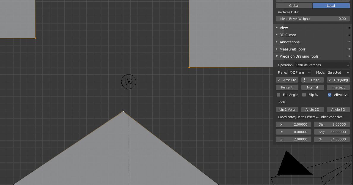
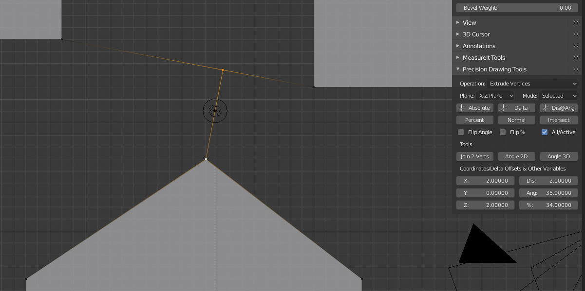
All the functions are in the new version now, here I am extruding all selected vertices to the point where the active vertex is normal (perpendicular if you prefer) to the imaginary line between the other two:
Or you can use the shear operator, with the 3D cursor as the pivot point and a magnitude of 1. If you want to stick with the scale operator, enable advanced numeric input and use sqrt(2) as your scale factor instead of doing the math externally.
Hi there, I’m a bit late on this thread and sadly haven’t got much to offer to the discussion, what it really got my attention is what you mentioned on you first post when you say you used AN (animation nodes?) and that you don’t need AN to execute the node. I have also built a nodegraph with AN composed of several nodetrees and would like to transform it into a addon but not sure how to do that, do you? I know AN can writhe the execution code from a nodetree but when you have a bunch of those it doesn’t work and it still need the AN addon to work.
Please if you have any info on this it would be very much appreciated. Thank you
I am a bit busy just now so I will get back to you later today. Basically I used all the functions from my node in the Add-on, but made other code to make it an Add-on. I had to learn how to do this first as I had never done one before…
Cheers, Clock.
Edit:
I will be uploading this code to my website soon, once all the debugging is done.
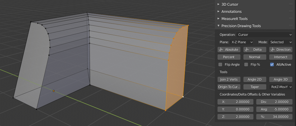
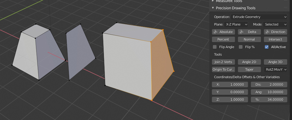
Here is the current state of play - I have added the “Taper” Tool - this allows you to effectively “Shear” some vertices, but instead of the Blender system where you just move along an axis for a set amount, you can put in the angle of the shear. Here is before:
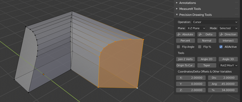
The Active Vertex is the rotation centre, I am working in “RotX-MovY” mode, which will effectively rotate the face about the Z axis and move the vertices along the Y axis, here is after:
I know you can do 45 degrees by normal Blender shearing techniques, but what about the other end that was done to 19.5639 degrees?
I have also added the “Origin To Cursor” Tool, this works in Edit mode and makes the origin of the object the location of the cursor, without moving the vertices from their position in world space. The Cursor can be positioned using any of the PDT tools, or standard Bender tools. You do NOT have to exit Edit mode to accomplish this task now.
OK I am stuck again, using code from the 2.8 API docs, I wrote this:
        elif data == 'DG':
            ret = bmesh.ops.duplicate(bm, geom=[v for v in bm.verts if v.select]+
                        [e for e in bm.edges if e.select]+[f for f in bm.faces if f.select])
            geom_dupe = ret["geom"]
            verts_dupe = [v for v in geom_dupe if isinstance(v, bmesh.types.BMVert)]
            del ret
            bmesh.ops.translate(
                bm,
                verts=verts_dupe,
                vec=(x_loc, y_loc, z_loc))
            bmesh.update_edit_mesh(obj.data)
        elif data == 'EG':
            ret = bmesh.ops.extrude_face_region(bm, geom=[v for v in bm.verts if v.select]+
                        [e for e in bm.edges if e.select]+[f for f in bm.faces if f.select])
            geom_dupe = ret["geom"]
            verts_dupe = [v for v in geom_dupe if isinstance(v, bmesh.types.BMVert)]
            del ret
            bmesh.ops.translate(
                bm,
                verts=verts_dupe,
                vec=(x_loc, y_loc, z_loc))
            bmesh.update_edit_mesh(obj.data)
I already have bm established as the Bmesh from the object. Can anyone see what is going wrong, when run this, it just clears the selection and does nothing in the way of new geometry.
Yes I can you d***wad! I looked at it and you left the brackets of the set of geom=( blah, blah)! This works better:
                ret = bmesh.ops.duplicate(bm, geom = (
                    [f for f in bm.faces if f.select]+
                    [e for e in bm.edges if e.select]+
                    [v for v in bm.verts if v.select]),
                    use_select_history = True)
Extruded Geometry in “Direction” mode (Distance @ Angle) - works for “Duplicate Geometry” as well and updates the selection so you can just keep going… I also made the face on its own by this duplication method. It will work on Vertices, Edges and Faces all at once.
“So what!” I hear you cry, well a number of things:
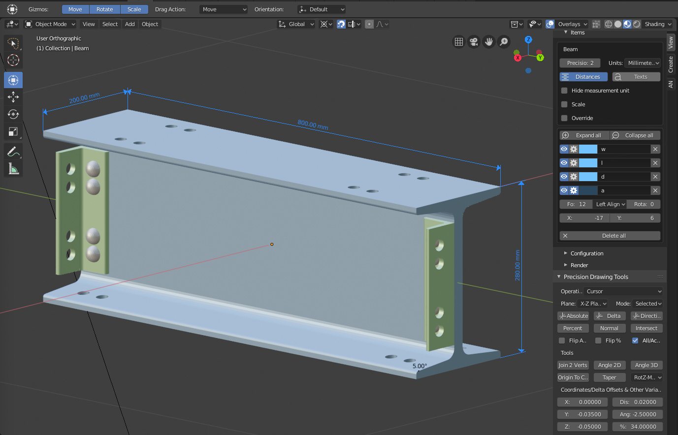
The beam and brackets are perfectly accurate, within the confines of double precision floating numbers.
The holes are not done with Booleans so the polygon (isn’t a “polygon” an empty parrot cage) topology is not wrecked, same goes for the bevels.
The flanges on the beam are exactly at 5 degrees and are not drawn by zooming in and putting the vertices as close as you can by eye to get an intersection. The brackets slope at exactly 2.5 degrees BTW.
It has dimensions and can be fully dimensioned.
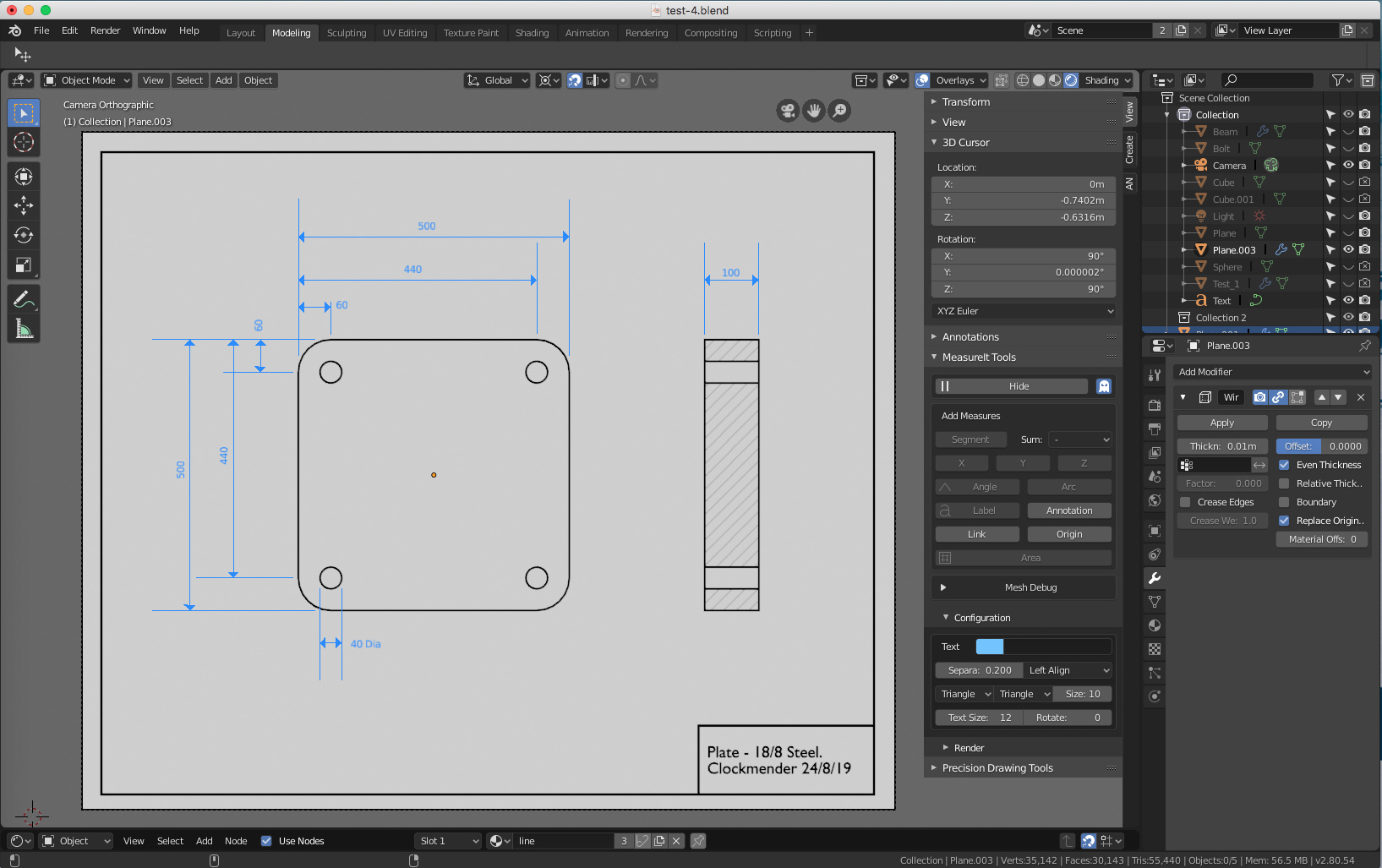
It can now be produced as an engineering drawing.
It was modelled using conventional CAD techniques.
I can now see a route to producing a proper 4 View (Front, Right & Top Elevations with Isometric) drawing, with a border, having now found out how to dimension and make them viewable in different orientations. I will of course add all significant dimensions before making the drawing. I am also playing with producing line drawings using Freestyle, but am not very good with that yet…
So why significant? Well it is all done with Vanilla Blender, MeasureIt and my PDT add-on, not a CAD package in sight. Well, I am pleased anyway.
Cheers, Clock.
PS. If you are wondering what it is, it forms part of the chassis of the latest Ford Pickup Truck.
You can do it this way, but if you have a large number of properties to register, using bpy.types.PropertyGroup and bpy.props.PointerProperty can sometimes make for cleaner code.
This adds several properties into TestPropG class when register runs. It can then be stored as a sort-of “super property” through the test_the_pg PointerProperty which gets stored in the scene.
Each time you call “My Basic Operator” from Blender’s search menu, it will print out the previous time “My Basic Operator” was run.
I think there’s a better way to implement this with the CollectionProperty, but I can’t remember it’s implementation details right now.
I am not at home till later today, I have a github, but it is not on there yet, I will either upload it to my website, or github later today, it is not finished yet and there was a no help file either!
Thank you! I was a bit busy yesterday at my flying club, so please excuse short response.
I have uploaded the Add-on to my website, I have not had time to do any help for this yet, but I hope it is reasonably intuitive and if you have any question, please ask and I will reply.
Both versions are there, but the UI version has more options and is better written. I have not had time to completely test it yet so there may still be some errors…
My GitHub is currently only concerned with my Animation Nodes additions, so I really need to make another project for this work, again I can do that in time.
@_nBurn Thank you very much for that code, I will look at how I can implement this, it seems a better idea than having lots of individual variables. Currently there are 13 variables including the enumerators for the options selectors, so it is definitely worth doing this.
I have a list of object in an outside blend file that I got with this code:
path = str(bpy.utils.user_resource('SCRIPTS', "addons"))+'/clockworxpdt/parts_library.blend'
with bpy.data.libraries.load(path) as (data_from, data_to):
    object_names = [ob for ob in data_from.objects]
I would like to display this as a list in the UI Panel so I can select one of the objects, then I will append this object to the current blend file - this I can do, but I cannot seem to make the list selector in the UI panel, can someone help please? I think I have to use a template_list but I am not sure… Does someone have a worked example for this?
The variable object_names is a list of the object names from the external blend file, so this code will append the second one in the list:
The Parts Library is now at Beta 1 stage. I can either link or append objects, collections and materials from my library to any blender project file. I made the objects without materials in the library, so I could then add them to a project and link a material from the library to the appended objects. That way you don’t get a shed load of copy materials. It all seems to be working well at this stage of testing, but I need to try to break it. I have also done some cleaning of the code for the PDT Drawing Tools bit, but not uploaded this to my website yet.
Appended objects are positioned at the cursor location, rather than at their original origin point, this makes sense to me when assembling something from library parts, just placed the cursor where you want the part and append it, it is already then in the right place.
I solved the problem of creating choices for whatever is in the library by trickery, lateral thinking and black magic - my favourite kind of development tools.
It has been a pleasure reading through this thread every now and then. I didn’t manage to read each and every post, so maybe I’ve missed the bit. I was wondering if you have considered custom construction planes?
This is on my ToDo list, I want to be able to use the view rotation and to set that with precise values (like rotate the view 17.5 degrees in Z, then 11 in X), but I don’t know yet how to translate Global values in Local for the view, so if I have a delta of 1,3,1 in Global it is easy, but I have to work out how to translate that into Local in the view orientation of 1,3,1… I think I have to use Matrix Maths, but I am not sure yet. I would then add “Custom” to the working plane selection, which would mean “Current View Orientation”.
I hope to be able to do this soon, so if anyone wants to point me in the right direction, I should be most grateful!
Cheers, Clock.
EDIT:
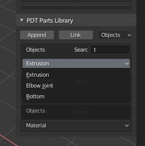
I have now added Search Strings to the Parts Library options so you can just search for objects with “gear” in them for example: