We are testing little help popup for PDT Command Line:
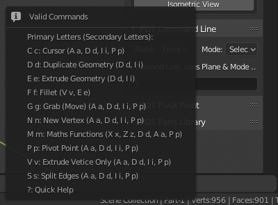
Type ? into the command line and this pops up. Thoughts please!
We are testing little help popup for PDT Command Line:
Type ? into the command line and this pops up. Thoughts please!
for me is ok, maybe also a small quick example of use on top
(as do the help of the programs shell command lines)
hei @clockmender , you just reminded me that in the future a next challenge could be a small programming language to build and assemble objects in a precise way… as does openSCAD ![]()
![]()

![]() think of it better
think of it better
mmm maybe it is a theme in common with what will be everithyng nodes for the meshes?
@jacqueslucke I’m right?
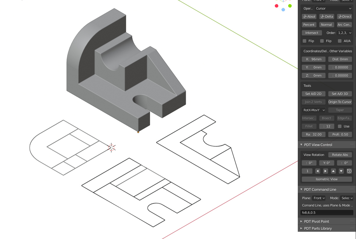
Uh, is it just me, or is rough (vertex) 2D sketching in principle as easy as:
If you want to move vertices and snap them to the grid, you can then go into Transform mode (‘T’), select a vertex (left click near a vertex) and then hold down CTRL+SHIFT to snap to the finest visible grid?
If you want to create a closed polygon, you can select two vertices and select ‘Vertex’ -> Merge Vertices (ALT+M) to merge them?
Then when you’ve created a rough sketch, you can use the PDT tools to ensure that the line lengths, angles etc. are precise before extruding?
EDIT: When working with machine parts, the standard dimension is mm. As such, we probably ought to consider having a dropdown in PDT Design that sets the viewport scale such that the large squares are 10mm wide (1cm) and the small squares are 1mm? That way, visually scaling vertices to the grid via Transform can be done in increments of 1cm (CTRL) and 1mm (CTRL+SHIFT)?
Perhaps this could be coupled with removing the default 2m^3 cube and selecting an editing plane from within PDT Design, which will then create an empty mesh with the selected sketch plane in its name (‘PDT Sketch Plane - Front (X-Z)’?), while scaling the viewport appropriately and selecting the 2D view as dictated by the PDT Design dropdown?
It’s actually easier than you have said my friend!
I will try to find some time to do this and list the commands, before my holiday, otherwise when I get back, Mrs. C. has a very long list of tasks before we leave…
I offer this image for discussion and I’ll see what happens… I know it would be better with some dimensions, but I don’t have the time right now.
Cheers, Clock.
I have already done this kind of work with Animation Nodes in the past, very easy to do, but I am waiting in 2.8 for AN to become more than “just useable” again, as it was in 2.79.
I made an animation of a gearbox being assembled from parts flying into the camera view, it was quite easy to achieve back in the 2.79 day, but AN seems to be drifting away from this type of animation towards, Particles, etc. nothing to interest the Mechanical Engineer. I even made a load of nodes to assist me in these tasks, but I have no idea which direction AN will go, so have not bothered much with them recently. If all focus for this type of work is lost, we will have to find another method to animate mechanical scenarios.
Here is a piece of my madness, put your volume up a bit:

All Animation was done in 2.79 with AN.
Cheers, Clock.
Listening to Jacques talking a bit about the next steps, it is probably a long way indeed.
For reference also, here another talk from the Blender Conf 2019:
Yep, into the great yonder of “who knows when”.
As for the talk, Daphne clearly has not explored the precision capabilities of Blender to the max like I and others have. We can model accurately, quickly and we do not need CAD packages. This talk is basically saying “Blender is OK to play with but serious work cannot be done”, I disagree profoundly and as a trained draughtsman and highly qualified mechanical engineer, I feel justified in my opinion.
But at least people will now talk about using Blender for serious work a bit more, so there is a bright side. I wonder if BF would like me to give them a talk next year… ![]()
Cheers, Clock. ![]()
Maybe your tools will change her mind? ![]()
That would actually make sense, especially in a year, when the add-on is really mature ! ![]()
Maybe? I think the most important thing is to change the concept of how you work to model with precision and good CAD topology. That means adopting some CAD techniques, or more importantly Draughting techniques, ones I learnt many years ago when I did all my design work on a 6ft x 3ft 6in drawing board using plastic film, plastic lead and drawing instruments.
The techniques are totally different to traditional Blender Polygon Modelling ones. We hope to have more examples of good Designer workflow and to explain the concepts better, in the add-on’s Wiki, but that is going to take some more time.
@jdelbe Thank you for the kind comment, the add-on is only a few months old, so we need more time to mature it, which we are working on all the time.
Cheer, Clock. ![]()
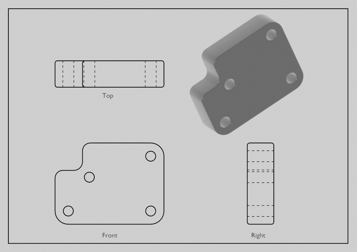
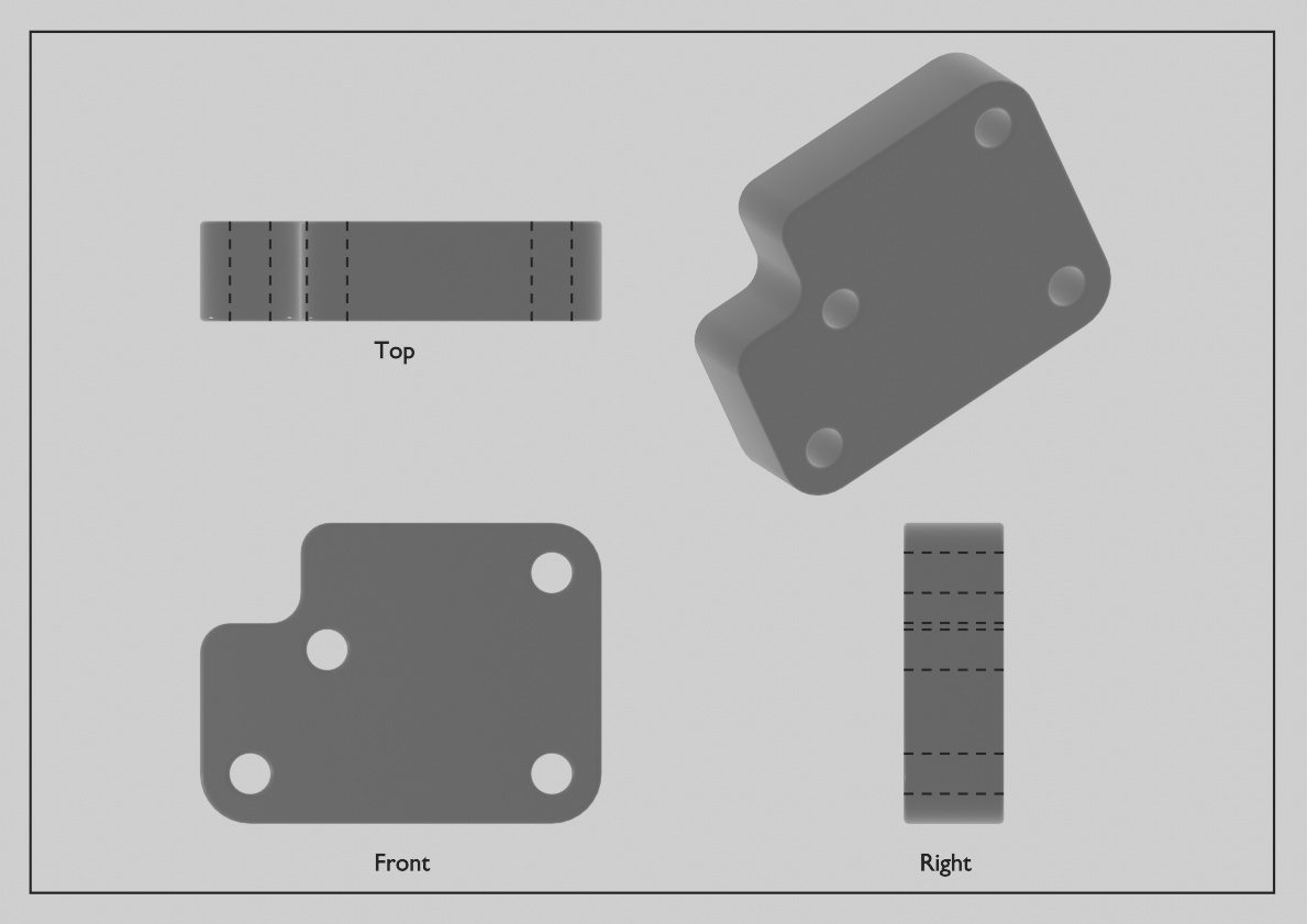
Two sample renders for consideration and thoughts:
What do you all think as regards producing “Drawings”? Don’t be shy…
We are planning for our PDT 2D Draw module.
Cheers, Clock.
This is awesome! It’s only missing dimension information drawn in the plans. There’s so much potential here.
I’ve always thought dimensions should be another object primitive, and that they should be place-able with the “Measure” active tool, and visible in the viewport and / or render view without the tool selected.
Some sort of parametric editing of dimensions would be very cool, where you could place them and they could stick onto certain vertices or edges. And having that process interactive in the viewport would be awesome.
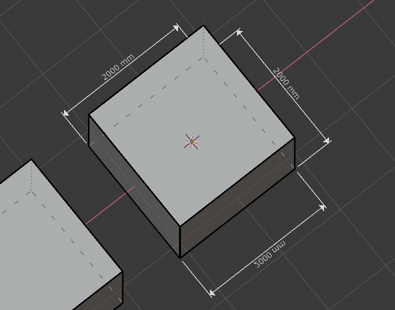
We can do this with MeasureIt at the moment, but we need to modify this somewhat to bring it up to drawing standards…
Example here:
The lines and gaps are not right as delivered with Blender, so we need to work at this. But they are tied to the geometry already.
Cheers, Clock.
PS. Thanks for the kind comments!
did you take a look at measurelt-ARCH?
It’s much better, but I could not find a way to delete an incorrectly placed dimension…
I will look more after my holiday, starts tomorrow, ends 30 Nov… @ermo will be in charge!
Cheers, Clock.
EDIT:
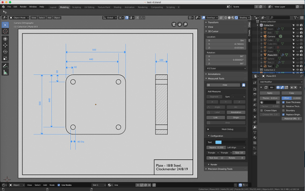
I need to sort out having the dimensions always read from bottom & right of drawing only, in line with Drawing Standards, but I like the setup and I like the gaps between dimension line and object, dimension lines are also very consistent, I like that also, very nice:
Outlines done with MeasureIt-Arch - very nice.
I have raised an issue with MeasureIt-Arch for this and also how to delete incorrectly placed dimensions, I couldn’t find a way to do that either. But now I must pack for my holiday!
find the author here on devtalk or on blender artists and talk with him …
surely together will reach interesting conclusions
I raised an issue on his Github, I thought that was the best way… He has made some good improvements, but I can’t delete dimensions with his version and I need to be able to “flip” the text. Thanks for the reply!
Cheers, Clock.
I don’t really know this addon, but it seems strange to me that you can’t delete some dimensions