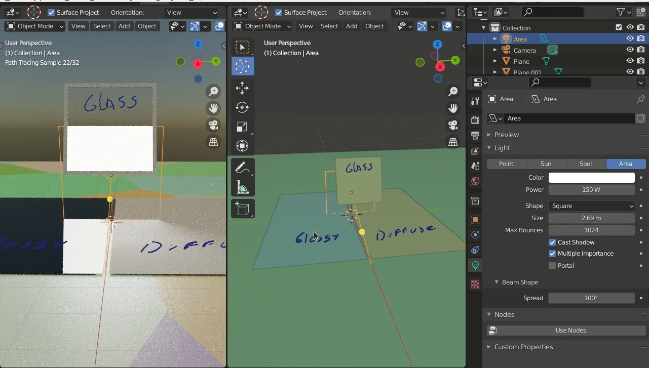
Hi i have been testing the new spread for area lights in cycles and it works really well for diffuse rays but for glossy rays the area light turns into a circle, this looks really weird in reflections or refractions,
is this a bug? or its by design
Hi, yes, this is “by design”.
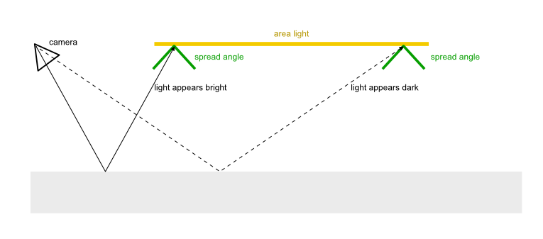
The feature works by dimming, and eventually “eliminating” light rays coming from the area light as a function of their emission angle. Practically this means that all the points on the area light surface that you look at an angle greater than your spread parameter, appear completely dark. This shape must naturally be a circle, no matter what the overall shape of your area light is. I think the best way to imagine it is thinking a real-life spotlight grid, that this features aims at simulating:
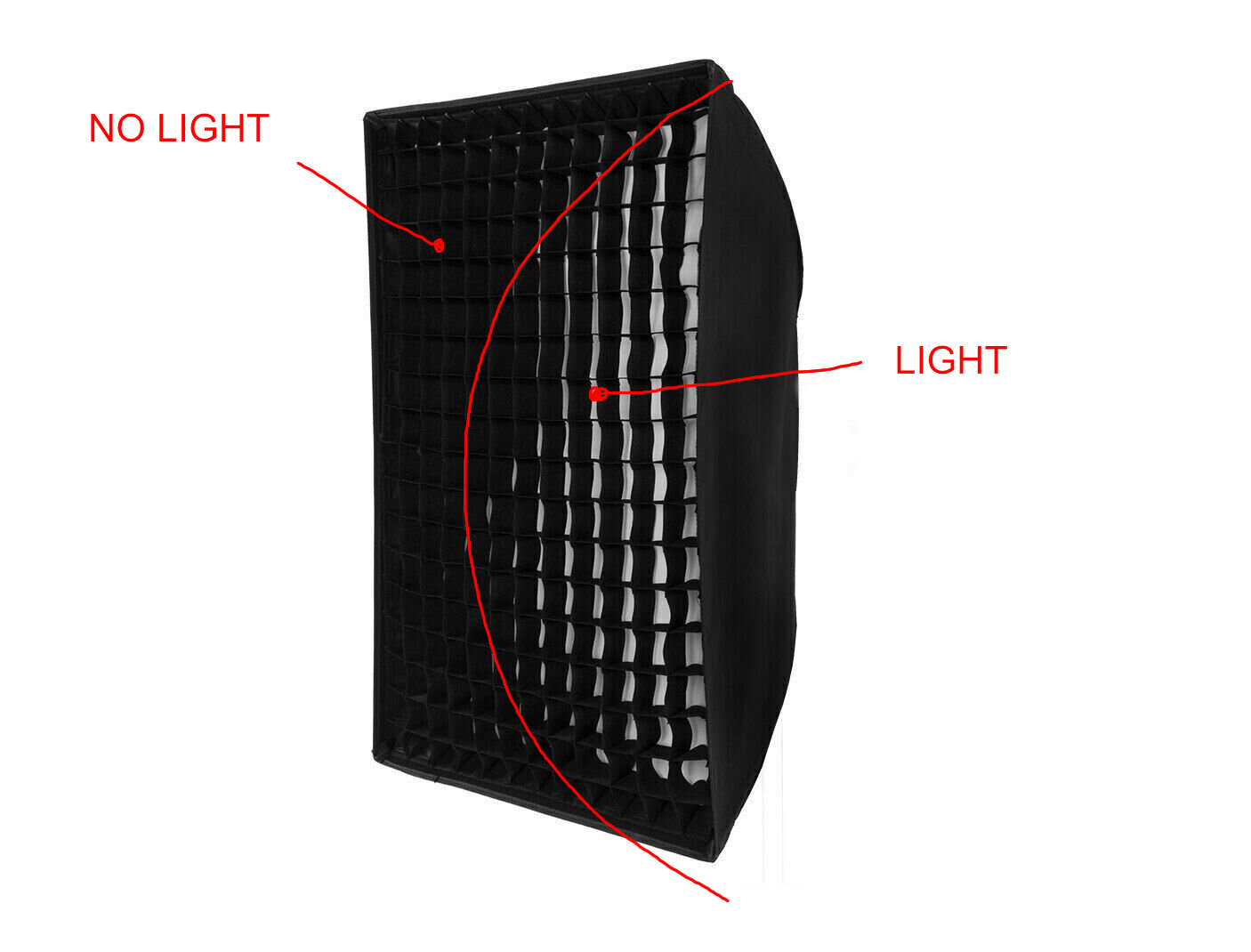
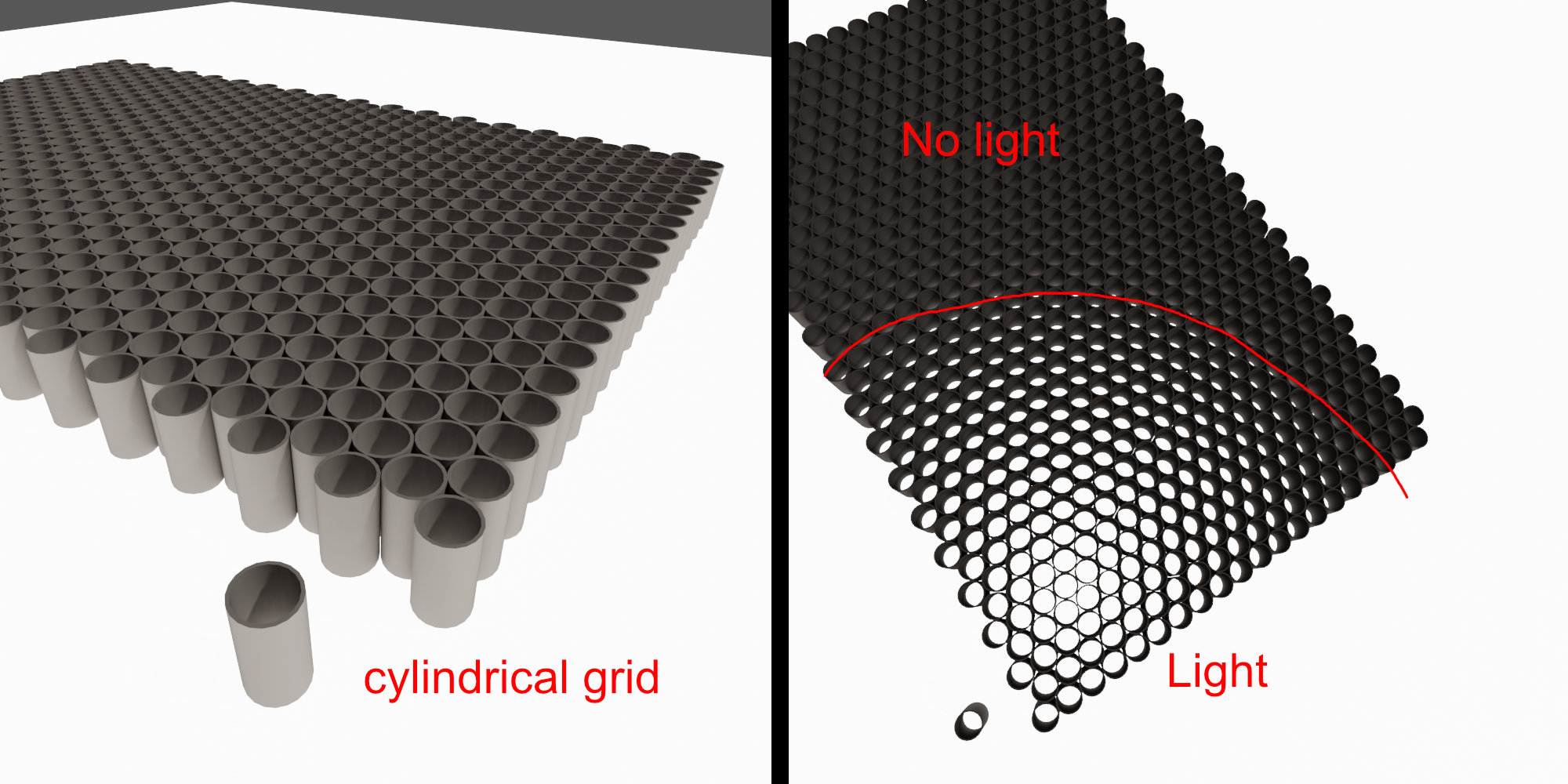
OK, this example is not perfect because the grid cells are square (thus appearing wider when looked in the direction of their diagonal; think of them as hexagonal, or, even better, cylindrical ones) and because the grid is rather wobbly and imperfect. But it should give you the basic intuition behind this phenomenon.
3 Likes
It’s working as expected, or at least as any photographer could expect 
1 Like
Hello everyone!
First of all, a thank you to the developers is due, awesome feature.
However, since Cycles aim has always been flexibility for animation rendering, and lighting for animation means lighting stylization, you’ll probably need to break physics at some point (or since the beginning) in order to get a certain effect or look, or just art direct the shot or even the whole show.
I guess it wouldn’t hurt having a checkbox to keep the intensity at any spread angle, even having it on by default. Currently it’s tweaking two properties at the same time (spread angle and intensity) which is quite undessirable when lighting. It takes away control over the light, forcing the users to guess the intensity given the spread angle instead of just setting the intensity they want and the angle they want, no need for guessing. And since light intensity behavior itself is not physically accurate by default (no inverse squared distance falloff, at least to my knowledge, otherwise there woudn’t be a shading node to set exactly that on the light), it doesn’t make much sense keeping the current behavior by default either.
I understand the current behavior is logical for photographers, but just because it’s a physics phenomenom they can’t avoid, so they learnt to live with and compensate for it with the intensity. It doesn’t make sense porting the same limitations physics has over Cycles, at least not by default. It should be kept as flexible as possible, giving the option for physical accuracy if possible, of course, but not at the cost of flexibility.
My two cents.
Cheers.
J.
The thing is not only to maintain it correct for physics (and of course that the light behaviour does not break other parts of the render) but also that you need an algorythm that is capable of doing such thing, the current implementation works in a specific way, like a honeycomb, that means that it will behave in the same way as a honeycomb, other behaviour would be a different algorythm or implementation I’m afraid, so it’s not as simple as “make it not do that”.
This applies to both, reflection and perceptual intensity (the intensity is kept the same, but focused into a smaller space, so you perceive more brightness, but it’s just because you are focusing the light).
@matteolegna can confirm this, but I think it’s this way.
Hey! Thank you for your feedback.
I have to say I am not entirely sure I’m getting your point the way you meant it, so I’ll try to give a broader reply, hoping to answer, at some point, all of your concerns.
About the fact that the light appears as a disk when looked at directly (through a specular reflection or refraction): This has not really been a deliberate effort to have it this way. It’s rather an unavoidable consequence of limiting the spread of the light rays cast by the panel. The area beyond the “disk” appears dark because there are in fact no rays coming from the panel at such a “shallow” angle: in that spot, you are looking at the panel at an angle that is greater than the spread angle, and since we set a limit to the maximum spread rays can have, there can be no light at all coming from that region. There is really no way to avoid that.
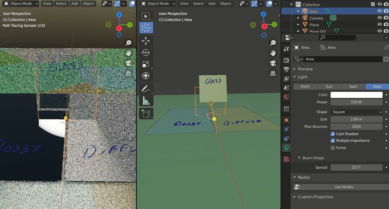
Talking about how the light intensity varies as a function of the spread angle: Originally, I had implemented the algorithm so that the light intensity of rays emitted perpendicularly to the panel never changed. This behavior is consistent with what photographers experience with grids.
This is a test render of the original implementation:
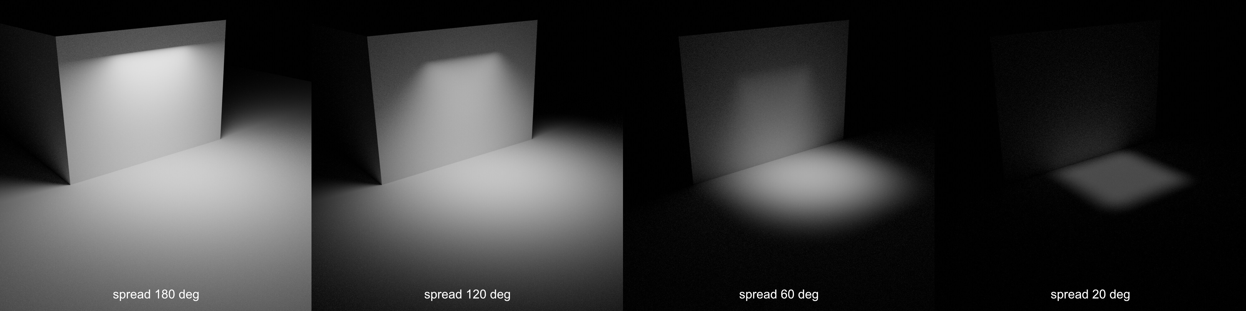
You can notice that at very narrow spread angles (20 degrees), the portion of the plane directly beneath the area light appears darker. This is because any given point on the floor no longer receives light from the entirety of the panel. The rays are now so directional that the light coming from the right side of the panel cannot reach the left side of the lit area on the floor, as that would require it to leave the panel at an angle greater than the spread limit.
This effective loss in luminosity has since been deemed undesirable and an internal compensation factor has been introduced so, as you force the rays into narrower and narrower angles, their intensity gets boosted to make up for all those rays that cannot be emitted any more due to the spread constrain. This aims to keep the total luminosity (i.e., the sum of all the light emitted in all directions) constant and independent of the spread angle.
Lastly:
This is the shape of the emission curve at various spread angles, before the “boosting” effect described above.
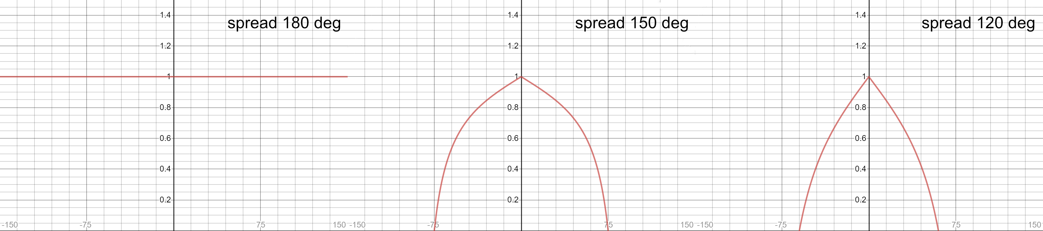
Let’s look at the case with spread 150 degrees: Light coming at 0 degrees from the area light (i.e., perpendicularly to it) is not affected. Light coming at angles above 75 degrees is completely eliminated. In between, there is a gradient modeled after how a grid blocks light.
You may ask: why such a model instead of a “hard threshold”? Something as such:
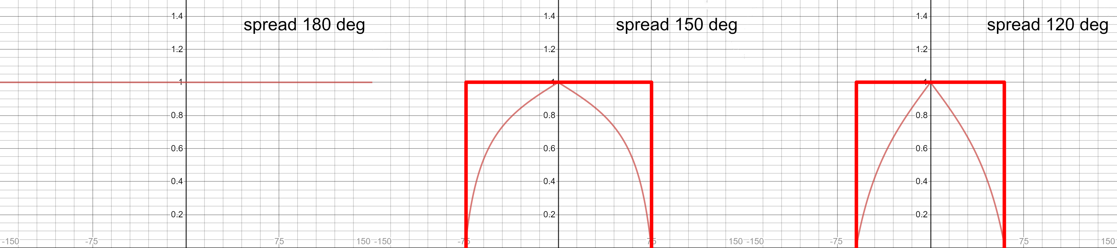
Well, yes, this is a bit of an arbitrary decision I took. I felt such a hard threshold, despite being easier to implement, would have produced results too far off any possible real-life light source (I couldn’t think of any situation where you might want to have such an emission distribution), it would have “watered down” the effect at broad spread angles (it lacks that sharp peak at 0 degrees), it might have caused noise and artifacts in certain situations, and, in general, it would not have been a good choice as the only model provided to the user.
1 Like
I have the suspicion however, that the current compensation factor is a little bit off, despite, overall, acting in the right direction. I need to think about it a bit more.
1 Like
Here as you can see the light get smaller in reflections
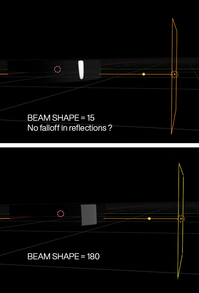
in other engines like REDSHIFT, light fall off (spread) produce gradient in reelections, which i assume is the accurate behavior and the behavior that is lacking in blender lights.
Well, I’d say in Blender this behavior is accurate for what it wants to model, that is a gridded area light, which, in real life, have an angle threshold above which they don’t emit any light. I’m not familiar with Redshift, but it must apply a different definition/concept of “light spread”. The question is not which is more accurate, as both are, but which is more desirable? I’ve been trained in traditional photography, so I used real-world tools as a starting point. Of course, a different implementation can be conceived and discussed. But as of now, it’s not a bug, but a feature.
1 Like
Okay, thanks for the answer.
So if I want to get that gradient reflection on some glossy object how do i go about that, without the spread option?