Thx Howard ![]()
3 Likes
Yes, lsscpp, have a bevel of any size regardless of underlying geometry will be my next big project on bevel. But right now I’m working on making Boolean better, and that is likely to take several more months.
11 Likes
Sorry Howard, I didn’t mean to put pressure in any way. And I know I already asked this 
The fact is that the moment I saw that slider doing the job I thought “wow, all the calculations are right there, behind that single operator!”
1 Like
@pablodp606 @Howard_Trickey @HooglyBoogly
Maybe conversing with Pablo would be useful. The discussions here may help with other areas of development, and could help create a more unified tool system.
Pablo’s Twitter: Blueprint tool
Blender Today: Live #71
1 Like
I found another issue with bevels and I weren’t sure if it’s a bug or a known limitation so I thought I’d post it here before filing a bug-report. I were trying out some pretty simple shapes with bevel modifiers and bevels earlier and found that the roundness of the bevel is very dependent on the underlying topology as underlying edges can skew your fillets a lot. Here’s a picture demonstrating the problem in it’s simplest form:

Top image is just a plane (without any depth) with a thinner section extruded out, the image below is the same as the top, just without the wireframe to make it easier to see the problem, the middle one is same shape just given some depth/thickness, right image is same as the proceeding one just with two loopcuts pushed up slightly which reintroduces the problem. The second model almost works but it’s not quite perfect, the third image just reintroduces the problem.
I did a quick attempt in Max just to see how it was handled in there and it had the inverted issue where the flat shape was fine but issues cropped up with the two other variants. I’m not sure if there is a solution to this problem, but I thought it might be worth highlighting just to be sure.
Let me know if I should post this as a bugreport instead.
1 Like
I can’t really tell from this picture what your model is, sorry. I need a .blend file.
Often when bevel makes an unexpectedly distorted shape, the reason is that object had a non-uniform scale applied; could that be the case here? Another reason for distortion is when ‘Loop slide’ is enabled; does disabling that fix things?
2 Likes
Here’s the blendfile with all three of those examples:
https://www.dropbox.com/s/xr41qrsk7d3rw1k/Skewed%20bevel.blend?dl=0
I tried applying all transformations, and turning off loopslide as well as playing around with different width methods, but I couldn’t find one that gave me a satisfactory result.
1 Like
OK, thanks for the .blend.
For me, bevel is working as intended here. Let me explain with the first example, where I’ve specified 2 segments for the bevel.
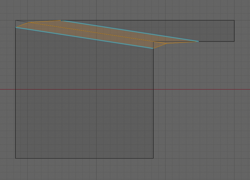
I’ve put a duplicate of the object behind the beveled one, and used wireframe view, so you can see the original shape.
Since you are beveling an edge (the diagonal one), and since the “width method” is “Offset” what is supposed to happen is that we move two edges away from the original one, parallel to it but on different sides of it. The move distance is equal to the offset amount. As you can see, Bevel has done exactly that in this case.
You could get more of what you desire by using the “Percent” method offset, but that is only really satisfactory if the adjacent sides have similar lengths.
You could also get more of what you desire by beveling the vertices (“Vertex only”) at the end of the edge, though that admittedly adds a lot more geometry if that diagonal edge is there.
As to why the second model in your sequence (the one with depth) seems to behave better: that’s because you also have given bevel weight to the vertical edges (that you can’t see from your top view) adjacent to the diagonal edge. For those edges too, bevel tries to make equal width strips on either side, and when it does so, because the side edges meet at right angles, the curve is not skewed. Note that this fights with the desire to make the diagonal edge have equal-sized strips on either side: it is impossible to satisfy both, so Bevel has to compromise. Luckily in this case it chose the non-skewed edge to prefer to make the spec match.
2 Likes
Can I ask that we stop using this thread to talk about future Bevel Improvements, since we have moved way past the title of this thread (GSoC 2018 - Bevel Improvements). And it is quite long. Of course you can finish any thoughts related to what has been posted here already, but the next person with a new Bevel suggestion or possible bug, please start a new thread called something more general, like “Bevel Improvements”. Thanks.
8 Likes
I think the problem is that the offset is very far from being even right now. I counted the grid spaces in your image and the offset on the horizontal line is 7 times bigger than it is on the vertical one, so it seems like something is going awry. I did try using vertex-bevels instead and, like you said, it works a lot better for this shape. Here’s a picture of the problem on a similar mesh, with the desired result colored white and selected:

Only problem is that if the shape isn’t flat vertex-bevels will give you other problems, here’s another picture showing what I mean:
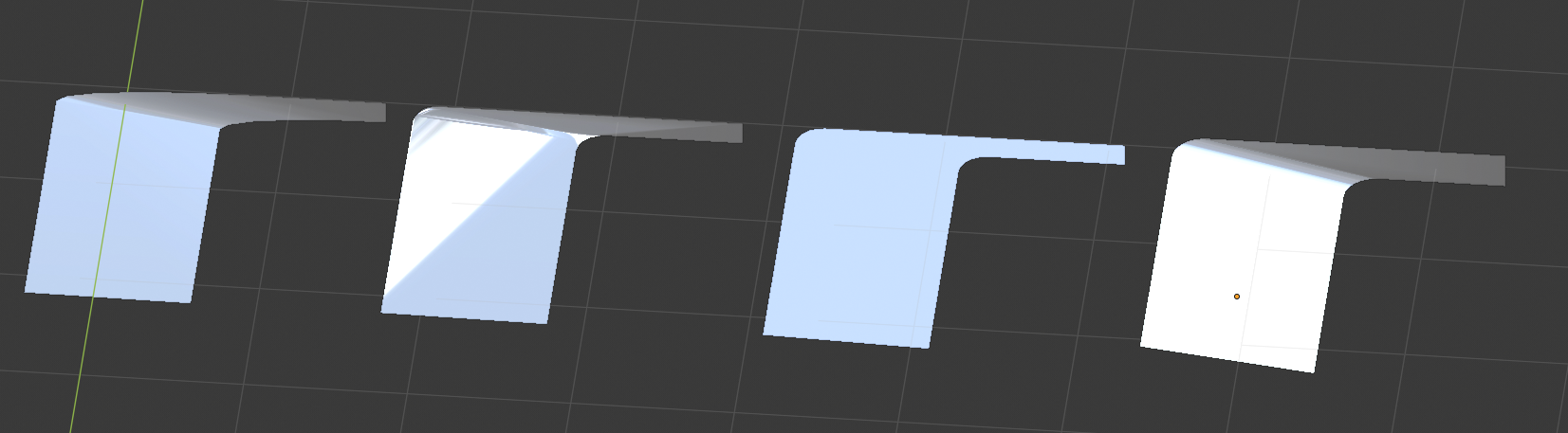
The first model is using a regular edgebevel that becomes skewed like mentioned earlier, second one is using a vertex bevel with the edge intact (causes shading errors), third one doesn’t have an edge so it just shades as a flat polygon and the forth one shows the desired result created using the preceding one with a manually tessellated bevel (which locks you into the shape so you can’t easily modify it afterwards). Here’s a blendfile with those models..
It would be great if the modifier could output some rounder results without needing any manual cleanup. I ran the last test in Max and that gave me the desired bevel immediately, so I would think it’s possible to achieve in Blender as well.
Thanks for having a look at this, Howard!
1 Like
I disagree with “the offset is very far from being even right now”. The offset is measured perpendicularly to the edge being beveled. If you look at the picture I showed, the perpendicular distance from the orange edge to each of the blue edges is exactly equal.
The unevenness you don’t like is a different kind of unevenness – the distance moved along the two adjacent unbeveled edges. The only thing that bevel has right now that is close to that is the ‘Percent’ offset mode. But Percent lets you say the percentage of the adjacent unbeveled edge to move along; what you want is to specify the absolute distance to move along those adjacent edges, thereby having them equal. I suppose I could consider adding an additional offset type, called something like “Adjacent”, to do that. Sounds like you really want that. Any others listening in here have the same feeling?
10 Likes
I would like it 
2 Likes
Dev1 - I don’t know what you mean. There is only one edge being beveled.
1 Like
@Howard_Trickey @RobinKarlsson
Wouldn’t beveling those edges independently with the same bevel profile work? If so, couldn’t a multi bevel option using groups work?

General workflow
- Select bevel modifier: multi bevel
- Make a bevel selection. (Bevel #1)
- Make another bevel selection. (Bevel #2)
- Edit bevel profile parameters.
- Apply bevel profile.
Bevel #1 and bevel #2 would be considered independent selections/bevel groups. Each would be beveled using the same bevel modifier presets. (A make Quads or Tris function could be used if the vertices are connected.)
I hope the above helps.
me too ![]()
intersting option for less artistic and more mechanical bevel
1 Like
Dev1, I think you are imagining that the black corner edges are the ones being beveled, so that you could do them independently? They are not. There is only one edge being beveled here – the one underneath the orange one, and it is being beveled along its length, not at the ends. The thing that happens at the ends is just the “termination pattern” for the beveled edge. And that pattern is determined by where the beveled edge’s offset edges meet the unbeveled (black, corner) edges. Which, as I was explaining to RobinKarlsson, is dictated by the “Width mode” being “offset”.
1 Like
Okay, that makes sense. The bevel is being applied to the edge connecting the two vertices of the intersecting geometry (the corners).
Instead of selecting the edge the vertices could be selected, then beveled. Anyway, the following concept should work for such a use case;
General Workflow
- User selection: Edge
- Modifier: Bevel
- Bevel amount: (defined by the user)
- Bevel offset amount: (defined by the user)
- Bevel offset type: Relative
- Relative to: Vertex
- Apply: Bevel
Behavior
- Bevel amount: defines the number of subdivisions.
- Bevel offset amount: defines the distance between the subdivisions.
- Bevel offset type: defines the bevel offset’s behavior (starting point). (Relative to the vertex of the selected edge.)
1 Like
Yes, would be a nice addition
OK, I’ll add the offset type of “Even distance moved along adjacent edges”. It won’t be hard to add. I’m going to wait until the dust settles with the 2.80 release before doing this, however.
Any suggestions for what this “width type” should be called? I was thinking of “Adjacent”, but open to suggestions for better names. Don’t want it to be too long (and strongly prefer a single word), so that the drop down menu and list of buttons in the modifier doesn’t get awkward to fit.
9 Likes
“isobevel”. ok answer needs more characters. 0:50 interesting way to consider UV after bevels https://www.youtube.com/watch?v=LpDFg1rh_nE