I don’t get it. Even with original modifies you cannot reference the object itself, For example if you use the shrinkwrap modifier and set a target to itself, It will tell you it fails to set value.
plenty of modifiers self reference. how else would the bevel modifier work? array? subd? etc.
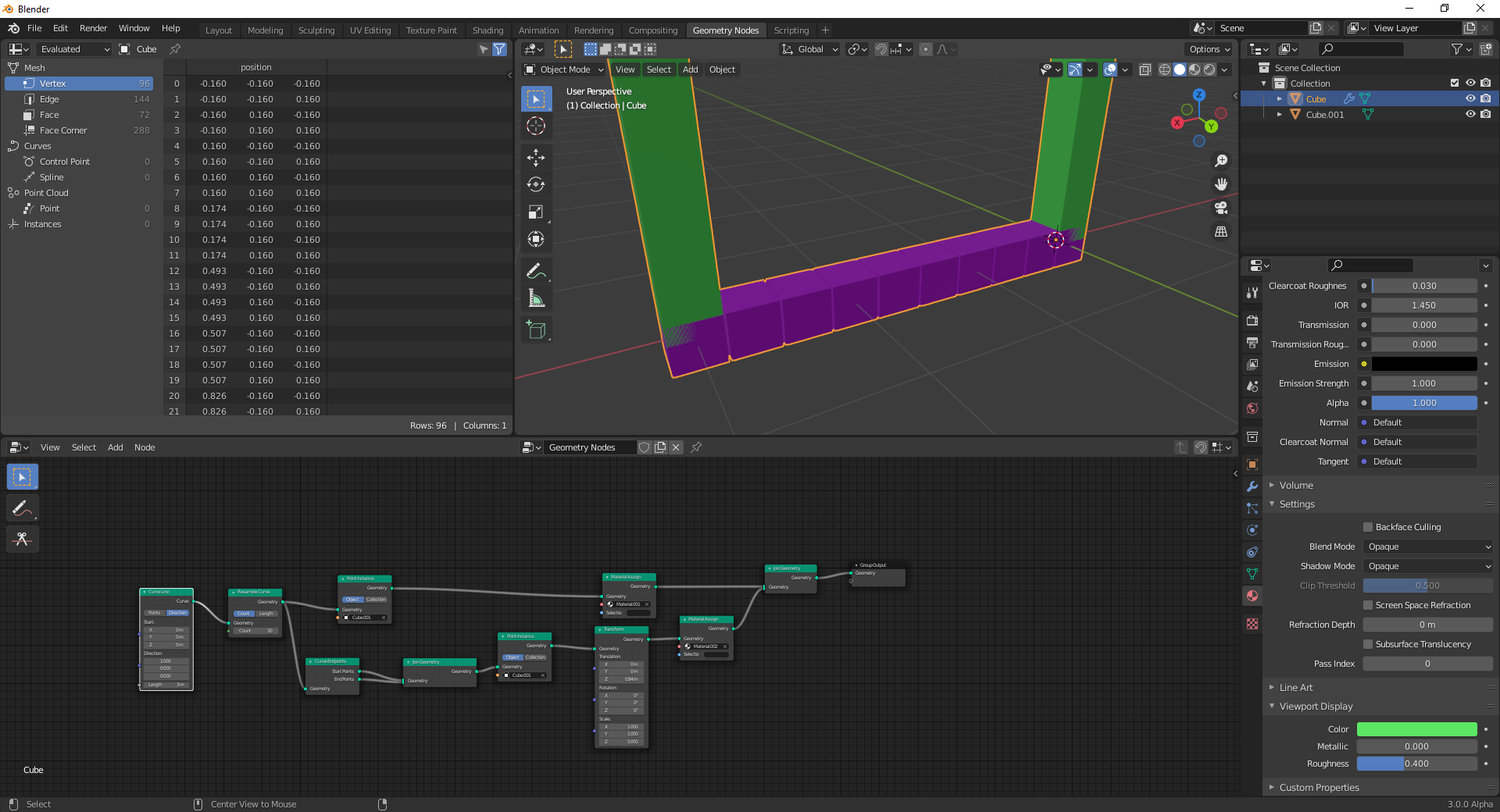
as a thought experiment- using only a single object, how would you create a radial array with geometry nodes? just a single GN modifier on the object you want to create an array of. I pick this one because it was the ‘golden child’ example everyone used to push back on a radial array modifier while saying ‘wait for everything nodes’ for the past 5 years or so. And now here we are with GN and still need an empty to create a radial array. The only difference is that now we use it as a node container instead of a rotation offset.
So that returns me to my original question- any plan to give GN modifiers the ability to self reference? a “Self” object node maybe?
I imagine it would become possible after the point instance node support instancing geometry data directly instead of only “object” and “collection”. I think this is mentioned here:
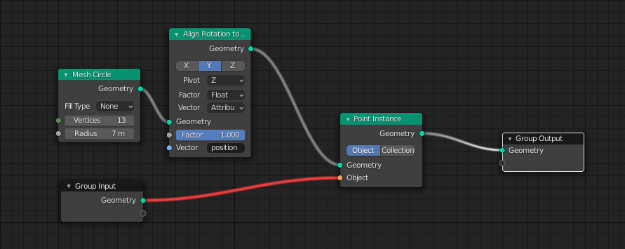
And after that we will be able to just do this:
1 Like
I missed this part, awesome!!!
How is this going?
I don’t know why I missed this but I have discussed this with my friends a while ago, the result we got was when using image textures all you have to do is to check to color ramp option in the texture panel:
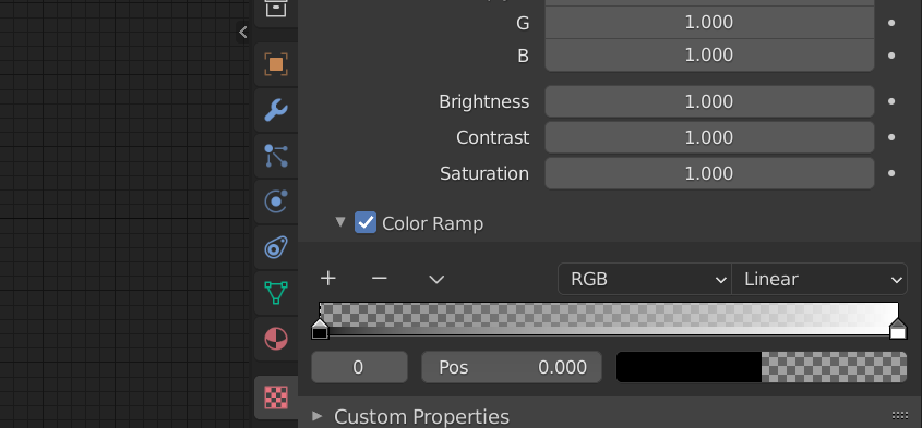
ok cool, that’s exactly what I was hoping to hear. thanks!
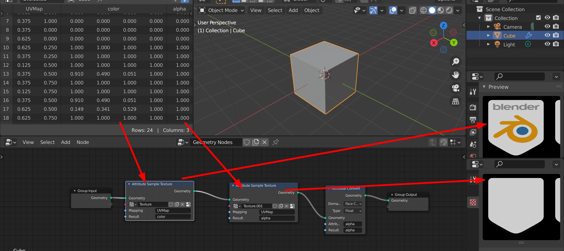
And how are we supposed to use the alpha channel within geometry nodes ?
Let say you want to use the alpha to mask out density ?
Spoiler: you can’t, there’s missing color channel conversion to do this and everything vector related will automatically cut the 4th member of the vector
2 Likes
True, I think we need a “Separate RGBA” node here.
But my method above can still be a workaround, With two sample texture nodes, one output the color and the other one only the alpha channel by checking that color ramp option. The two nodes would use two separate texture data blocks even though technically they use the same image texture.
1 Like
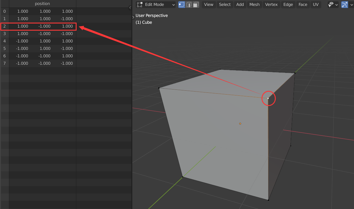
This is a feature suggestion
In the 3d window, click on a certain point, and the corresponding data of the key in the list should be highlighted to facilitate the adjustment of the data.
The previous method needs to change the value of X, Y or Z of this point to find out where the data corresponding to this point is in list.
After adding this function, the data corresponding to this point can be easily adjusted, which is conducive to improving efficiency.
8 Likes
One thing that just occurred to me is that control shift left click to see the geometry would be a more regular task rather than seeing the attributes. I think perhaps swap the shortcuts around with the node wrangler, though this may be an inconvenience as node wrangler needs to be enabled. Perhaps this could be fixed with the node wrangler stuff (or at least the important stuff) being hardcoreded into blender. I wouldn’t be surprised if this has come up before so I might not be saying anything new.
Same feeling here, the viewer node in the shader nodes would connect the textures to the output so we can see it in the viewport, but the viwer node in GN now is more of a replacement of the previous preview buttom on the upper right corner of the nodes, that only showed the attributes in the spreadsheet.
TBH I was expecting a viewer node that could temporarily connect the node to the output, but it turned out to be only a spreadsheet thing, which was kind of disappointing.
AFAIK the viewer node in the compositor works without the addon so I don’t think it’s a problem
If you all want information on this sort of thing, I suggest reading the commit messages.
They often answer this sort of “FAQ” quesetion. In this case: https://developer.blender.org/rB9009ac2c3d62e0d30d96b8d35ff5ff620cfe053b
As of now, the viewed geometry is only visible in the spreadsheet.
Viewport visualization will be added separately.
1 Like
I love the fact that GN modifiers can be re-used as node groups inside other modifiers. But I think the behaviour when a modifier has more than one geometry input is a bit misleading.
I create a simple modifier :
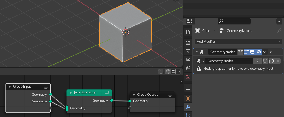
Obviously the second input does’t serve any purpose in this case, but I guess the modifier treats it as empty geometry and otherwise it’s business as usual, save for the warning in the modifier properties. But then it outputs a series of ERROR messages in the console, meaning something went wrong :
ERROR (bke.modifier): C:\Users\blender\git\blender-v293\blender.git\source\blender\blenkernel\intern\modifier.c:457 BKE_modifier_set_error: Object: “Cube”, Modifier: “GeometryNodes”, Node group can only have one geometry input

Now if I use this modifier as a node group inside another modifier on another object, it works seamlesssly without error.
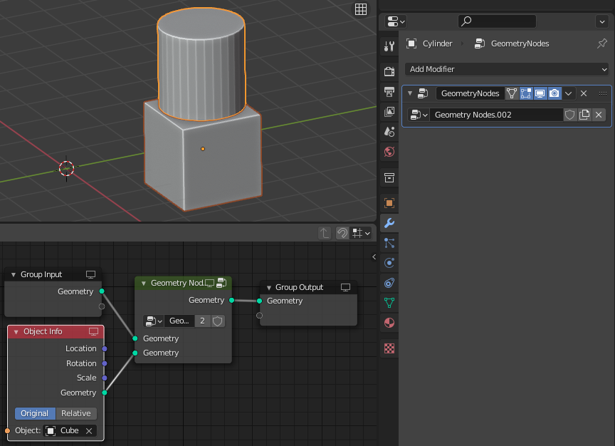
I have two questions :
-
Is the error message necessary ? Both in the console and in the modifier properties ?
-
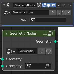
Could we transform the error message into a field to directly pick mesh data blocks (that would also be available in node group inputs) ?
Quick mockup :
1 Like
I have seen the new viewer node. It’s a worst solution that the old icon… but really worst.
2 Likes
With the help of such qualitative feedback, developers certainly won’t have a choice but to roll it back
I don’t see necessary to explain that
- Click
It’s better than
- Shift+A
- Search node
- click/enter to create node
- click in the node
- move node
- click in output node
- Move mouse to viewer node
- Connect node
Each time that we need to see a different data in the spreadsheet.
ctrl shift left click is the current shortcut which speed things up, though I think it should be alt shift left click cause viewing geo is a more common task
1 Like
the shortcut is good, I admit it. But having to create a node or delete it, every time we want to see something in the spreadsheet when we have a simple icon that does the same function…
I’m not saying it wasn’t a good solution… when there was no icon. Put the icon in the composition viewer and that’s it.
Newbie UX is better
veterans UX is better
visual feedback is better
2 Likes
perhaps have the group output have a spreadsheet output and a geo output so things don’t get too messy
Hi. any plan to add middle points to node “curve endpoints”? if we use instance on points we easy can change first and last. But if we do this we want separate them from all points to create new instances for middle points only?
for example we want create bridge. first and last points be bridge supports and middle points be bridge span. for now this 2 geometry be overlapping on ends of curve.