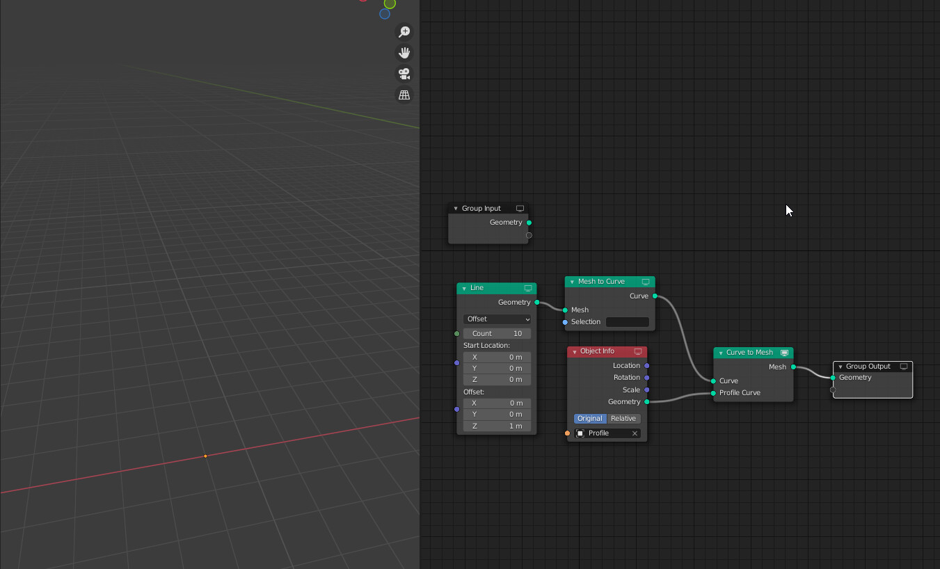
The profile in question is a bezier circle, and it works when turning a bezier curve I’ve set up manually into a mesh. I feel like I’m missing something here, especially since without the profile, it DOES output geometry. (It won’t let me post add more than one image, sorry)
I think there’s currently a bug/limitation that makes the Curve to Mesh node fail, when the curve is pointing perfectly vertical. (see: ⚙ D11265 Geometry Nodes: Add Mesh to Curve Node)
That might be happening here. You could try a line pointing to the side and then rotate it to point up afterwards.
Is there a way to take a point distribution and clone some other geometry to each point? I.E. I want a line to be generated for every point. Like a point instance, except instead of taking an instance or collection, it would take geometry as the input.
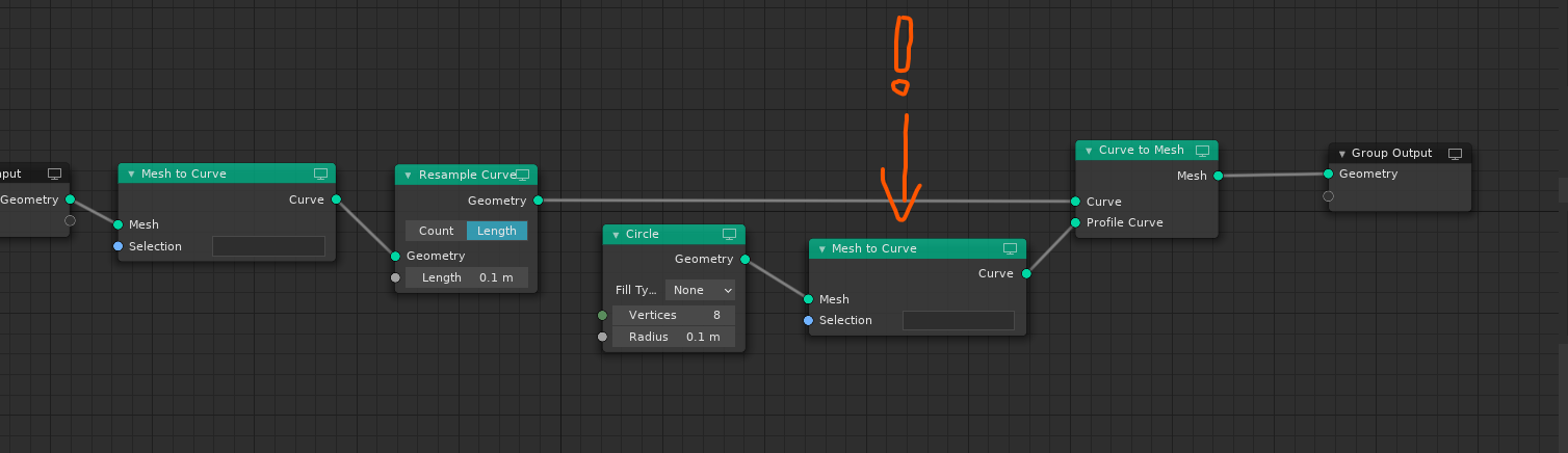
One of the significant design flaws is that curves and meshes are considered to be completely different, incompatible data types, yet they use the same pale green colored node sockets:
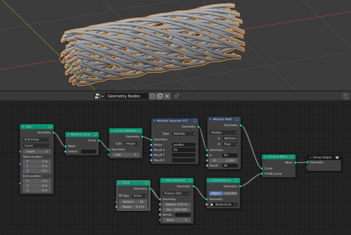
In this super trivial use case it was not immediately obvious that a circle primitive, which one would often imagine as a curve is actually a geometry, and first needs to be converted to curve data type before it can work as a profile curve input of Curve to Mesh node.
Worse yet, if you directly plug the Geometry output, which is pale green socket, into a Profile Curve input, which is also pale green socket, there’s no UI indication that something fails, and it fails silently, offloading the troubleshooting chores onto the user.
It needs to be made obvious that Meshes and Curves are two incompatible data types. They should not use the same node socket colors.
Whenever user plugs together two node sockets of incompatible data types (where no implicit conversion such as Float to Vector exists), the UI should make them aware of that, for example by drawing the node connection in red.
The “pale green node socket” is actually geometry in the broadest sense, and a geometry set can contain meshes, curves, and/or volume data. Separating these data types would complicate node trees a lot. Instead I think an error message along these lines would be best : “geometry set contains no curve data”
@HooglyBoogly why not also rename the primitive output socket to mesh ? or curve if it’s a curve ? I see the new conversion node already has it
Right. I had a similar thought to @LudvikKoutny initially when I encountered the general “Geometry” socket. It does have some downsides, but the alternative would be much worse. For example, how would you show that a node accepted only meshes or curves, or only point clouds and volumes, etc.
I think we could add an error message like you say.
Well, there would be lots of error message eventually, as there can be more than one errors occurring at the time. This would almost necessitate some sort of “error spreadsheet”
I still don’t get a point of geometry socket which signifies generic geometry but can only input specific curve type geometry.
Here’s what I propose:
Keep the generic geometry data type, but add also mesh, curve and volume data types. So for example primitives would output explicit mesh data type, which would be implicitly converted to geometry when plugged into geometry slot, being signified by mesh to geometry type color fade on the line connecting the two nodes (there was proposal for that somewhere).
So this way, if you have a node which outputs mesh data type, it could be connected into geometry data type socket, but not curve data type socket. So if you wanted to have a node which can input generic geometry, it’d have that pale green generic geometry node socket. If you had a note which needs explicit geometry type input, it’d have that explicit mesh/curve/volume input.
Well, then you’d already have two different error reporting systems, because we already have one
But yes, having multiple error reporting systems within one editor would be very Blender way of doing it, so that’s probably how it will end up
Why multiple ? this already exists so why not use it… if a node shows multiple errors they can always span several lines can’t they ?
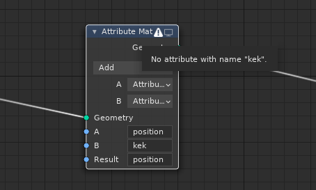
I’m not sure how many potential errors can happen with geometry nodes. Missing attribute, or connection between incompatible types… maybe these can be shown differently. I know node links go red, maybe attribute string fields could go red, too ? the same way object fields do when the chosen object goes missing. The “warning” icon on the node header could be a “hub” of sorts for these error messages.
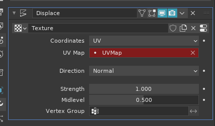
To me it just seems unnecessarily diverse. It’d make more sense to use just one design language. For example, node connection lines where there are two incompatible types without any implicit conversion would show red, and fields with invalid attribute name would be also highlighted in red.
This is already a standard in Blender:
But as usually, someone introduced a new standard (random warning icon clumsily squeezed into node header) instead of checking if there’s already existing one.
Yes, this is exactly what I suggested lol
I do wonder if the header warning icon is necessary. Hence my questioning what other potential errors there could be with nodes. I tend to prefer a solid color or a stripe pattern or something similar to indicate an error, but Blender uses node colors for node categories so it wouldn’t be obvious how to blend the two
Here’s what you’re looking for. Initial entry, at least.
Unfortunately, It is now not possible to build this kind of setup using only internal Geo nodes. You need an external curve for a wire profile.
UPDATE: or! alternatively, you may spread individual wires manually. It would not be very convenient to weave a thick bunch, although, everything you need for that kind of setup is already in Geonodes.
I know it’s less exciting to talk about this than talking about adding new features
are the developers aware of this limitation?
but I’m really wondering how this issue will be tackled in the future?
maybe by adding more options to the object info node?
Thanks for your response
I was indeed waiting for this node for a few months, hoping that it would resolve this limitation
I had also the same intuition
It would be indeed really nice and it seem quite logical too !!
Unfortunately, as confirmed by @HooglyBoogly this separate component node cannot read the “pointcloud” componement from an “instance type” object, because it seems that “instances type” object do not have any point cloud information. Once point instance node is used it seem that the point cloud componement is removed for some reasons (?)
maybe it would be possible to add it to the task?
tbh i don’t get why instances don’t retain their point cloud componement
I think that we can all agree that it’s important to give the users a flexible way to read the instances loc/rot/scale