Guys, I’m trying to push particles evenly from the sphere using normal data. Why it is not working?
Thanks!

Just a small oversight: You’re using the Attribute Math node instead of the Attribute Vector Math node 
(The Attribute Math node creates a Float attribute that is automatically interpreted as a Vector by the Point Translate node by simply using the value of the float attribute for all three components of the vector. That’s why the points are translated along the diagonal.)
2 Likes
Oh, wow. I need to be carefull. Thanks a lot.
Was banging my head against the wall for the whole day.
2 Likes
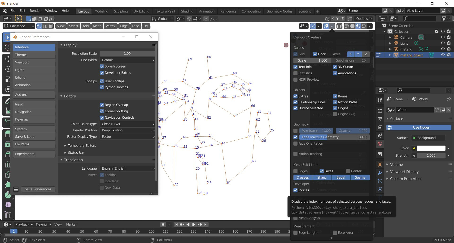
Is there a way yet to get the vert index of a mesh yet? I’m thinking about using Rigify/Skinify to get a starting series of verts, which, being procedurally generated, would always be in the same order and place, then referencing that to instance a mesh between 0 and 7 for the spine, 8 and 13 for the nose, etc.
2 Likes
Yeah, displaying vertex indices should really be moved out of the developer category now that procedural modeling is becoming a thing. I heard that there were talks about how to access the indices of a mesh but it was decided that an attribute interface was not a good way to go about it and it needed its own design. So nothing for now as far as I am aware of.
2 Likes
That’s awesome, delete edges and you can make a connect the dots game!

1 Like
Is it normal to have 2 attribute with the same name ? this supposed to happen ?
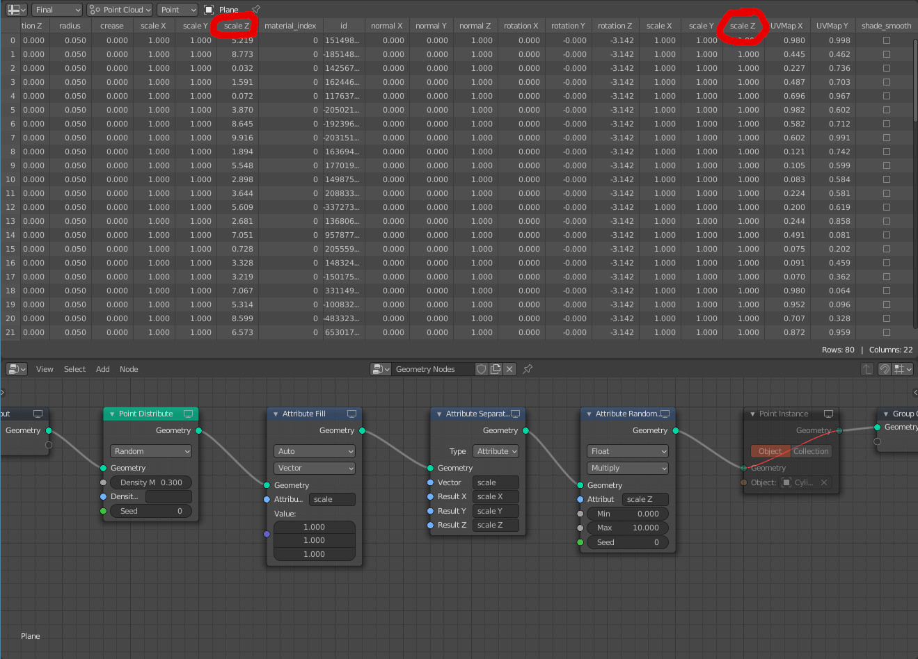
After instancing an object, the z scale isn’t randomize, i need to change the attribute randomize from float to vector so it can work
It’s not the same name,
there’s a “scale” which is a Vector type (with XYZ componement) and a “scale Z” attribute which is a Float ![]()
It’s just that the UI automatically add " X"/" Y"/" Z" column for vectors
1- im creating a vector attr named scale, its affecting the scale of the points,
2- i want to control the z axes, so i separate the vector to 3 floats
3- i want to randomize one of the floats
Is this wrong ? if so i still dont understand, we normally should have the ability to control 1 float from a vector
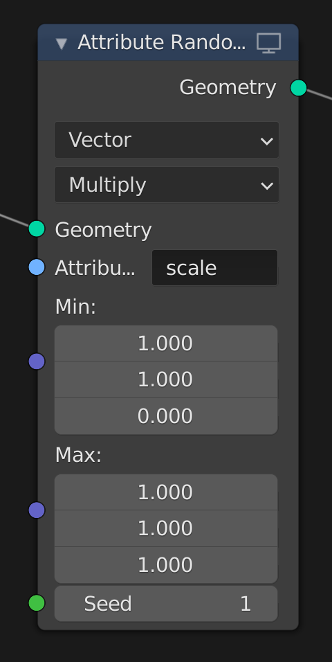
that’s what i ended up doing, it’s more straightforward, but the other workflow should have worked too imo
You would just need to rejoin them so
1 - create scale attribute
2 - separateXYZ
3 - randomise desired float
4 - combineXYZ to create the new scale vector
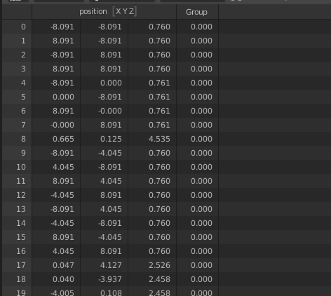
Vectors could be under the same “umbrella” like a sort of simple UI element, a tab that shows they’re components of a single vector you know. Especially when using separate/combine attribute nodes, the whole spreadsheet shifts or changes at every node you inspect, and it can be hard to keep track then.
By the way shouldn’t Blender follow the OOP convention of using dot notation? (position.x instead of Position X)
Anyway that spreadsheet completely changes the game, I feel like a mechanic now that I can lurk under the hood so to say. That’s great!
2 Likes
It got me thinking of how to do this in GN. That would be dope right? like constellation lines connecting with cool pyrotechnics, in sequence. I’m afraid I need all the loops in the world. I’ll still try maybe it’s worth a shot
2 Likes
I do think that the way blender displays vectors and colors in the spreadsheet is kind of iffy and unclear as to the fact it’s a component of an attribute. Personally I would like to unify under a sort of array notation ([0,1,2…], [x,y,z,w], [r,g,b,a]) as I feel that it expands better to containers, matrices, and more complex data types without too much visual hangup. Plus it’s more industry compatible.
5 Likes
I do think that the way blender displays vectors and colors in the spreadsheet is kind of iffy and unclear as to the fact it’s a component of an attribute. Personally I would like to unify under a sort of array notation ([0,1,2…], [x,y,z,w], [r,g,b,a]) as I feel that it expands better to containers, matrices, and more complex data types without too much visual hangup. Plus it’s more industry compatible.
Better? (it’s just some Ps)
7 Likes
It’s perfect ! Quick git push it while they sleep in Amsterdam !
3 Likes
I was thinking more of the [x], [y], [z] being right after the name on each column. The combined columns look good for simple vectors… But try mocking up a 4x4 matrix attribute and you will see what I mean.
Randomize Attribute node seems to randomize an attribute by its id.
Trying to implement a basic 2D perlin noise node, I have problems to get a noise done which only depends on coordinates inside ‘position’.
It would be nice if it is possible to enable to randomize an attribute by its value instead of its id.
Unitizing and data min max
I am having a hard time unitizing data (mapping item bounds between 0 and 1) without access to individual items in lists.
Map range attribute would be the easiest way but I don’t see a way to get the min and max values of a data set.
For example I want to unitize distances from verts to an empty. I thought the the color ramp could automatically remap but it doesn’t, all values remain the same and values >1 become one.
In this case, dealing with points, I thought I can use the bound box node to use min and max bounds as coordinates into the map range node but the data gets muddled. The bounds node outputs 6 vert positions, so it is still a list from which a specific value needs to get extracted
So at the moment I have to manually specify the in bounds of the map range node and keep the out bounds to 0 and 1.
- There should be a way to get the largest and smallest value in an attribute list
- we should have access to the invidual points of the bounds node
Grid primitive
Within the brick wall examples I keep making and testing, something else has popped up that would be useful to have.
At the moment the grid primitive doesn’t work well for objects that need to have a constant size as we first specify overall size and then the number of subdivisions. It would be really useful to have an option to toggle total size or cell size by the x and y inputs.
I am aware we can do that manually with a few math nodes or with array modifiers before the geometry nodes modifier but from a UX point of view it seems the grid node can handle that