Hi,
I’m not sur that the Attribute proximity handles the instances right now.
What’s the purpose of the Point separate node,he’s doing nothing because the ground attribute is empty.
What are you trying to achieve as effect, maybe we can find another way ?
Oooohhh ok. Probably because of instances ! thanks.
The ground attribute is a positive boolean used to separate the ground from the spheres. Since I didn’t know what caused the “attribute proximity” to dysfunction I thought explicitly separating the geometry might solve it.
I agree, even though I’d be more down for a proper falloff node/system for controlling attributes of objects and particles, as using the proximity node (or modifier) 1-it doesn’t have a volume option as you said.
2- relies on the number of faces that the vertex group of the object has, plus if you want to visualize the weight paint “falloff” you have to enter the weight paint mode of the object every time. Having a Falloff node that relies on e.g. Empty objects (their position and scale) to control attributes, with maybe a dedicated visualization method, would be amazing.
4 Likes
+1 for a proper falloff system for controlling attributes. Proximity is fine, but more options are more than welcome. The falloffs can create more flexibility in the end.
1 Like
As far as I know it’s already possible, we just need to remap the result of “attribute proximity”. We don’t have an “attribute map range” or “attribute curves” nodes so I tried with an “attribute colorramp” but I guess it outputs a color since I can’t visualize it into a vertex group. Creating a vertex color layer with the same name doesn’t help for some reason ?
Anyway the process is : invert the attribute (1/attr), and then remap, or multiply… does what you need.
If you run a curve or remap on the result of the attribute proximity doesn’t actually remap the range of the affected proximity per-element, it remaps the result of the combined distance field. So if you want to remap the range at which elements have an influence you wont really be doing that so much as you will be creating a gradient of the max combined result of all distances giving it a “metaball feel”. Perhaps this is acceptable in most cases but I can definitely see areas in which this might not be.
What is the situation with duplicate attribute names?
e.g.
I have a vertex group named scale, it is ignored but as a user I don’t know that it is reserved.
I have a UVmap and a Vcol group with the same name or using a reserved name.
I must admit this is way over my head ! can you please explain like I’m five ?
Try this: in an image editor make two slightly overlapping large dots with a soft brush. Now use a curves adjustment to play with them a bit. Take note of the results. Now do the same but put the two dots on seperate layers and apply the curves adjustment to both layers individually. This should better visualize the issue.
I followed your steps and observed the pattern of “capillarity” so to say -I mean the transition between the dots didn’t appear at all if I filtered them independently. I don’t understand what is going on, I must think about it.
Was looking at the GN chat and saw what Simon was talking about. I agree with this, because all the math that is done between attributes is all done linearly (geometry output to geometry input), you really have to spend some time parsing each node to see what operation is being done. I’m already happy with how in such little development time we can already so much with the nodes, but perhaps UI could be better yet.
Then this morning I saw this in GN chat:

I LOVE the idea behind these! I believe what I’m seeing is a giant node that has a right side with a geometry input as well as several commonly used attributes, a middle open field for math operations, and a left side for binding it to attributes as well as geometry output. Right?
I think it’s smart that blender wants to make it so that you cannot separate attributes from geometry. There are probably technical reasons behind that too, but I like how it keeps things linear which is easier to read. The issue is that when it came to attribute math, because everything sorta occurs in a single node it can be hard to read. You chose what kind of data you are using at the top, which changes the inputs on the bottom of nodes, there is you always need to type a result; it’s all fine, but I do think it’s a bit cumbersome to parse, and obviously others think this too, like Simon.
The way portrayed in these images has a more natural visualization of the math by far I think. Instead of looking up and down on the current attribute nodes and figuring out what is going on, you just look to the left to see what attribute/attributes are going on a math adventure, and you see the path it takes like one would already in blenders other departments, like shading etc. You can also probably do all the operations that you need within it instead of using 1-4 attribute nodes, unless you specifically want to separate unique operations in their own respective nodes. It’s so clean!
A downside of course is that this “node” is enormous, and would take up a lot of space in nodetrees. To be honest I had had my mind on this for a while, because by the time parametric modelling rolls in I really like to keep my trees having a very “linear and obvious” flow. Specifically what I mean by that is modelling operations and simulations etc, by name already give you an idea of what is going to be happening. Whereas, with all the attribute nodes, you know something is going on, but you gotta dive into them to understand what is happening. Currently the way I deal with this is just by grouping all the attribute nodes together, as for many operations you will need 1-4 or more. Then I just name the group saying it’s intention, like this:

That could be 7 nodes, but as far as the nodetree overall looks is concerned its just 1 node. The negative with this is that I’d say probably 50% of the time the scenarios are really just single use only, and won’t be used elsewhere. I dislike how that creates a nodegroup. I just want to tuck away my math for space and clarity reasons without creating a nodegroup or any extra overhead.
So I was thinking. Why not create a new paradigm, where we have the giant node from above, but you can use “tab” to close the middle portion:

It saves space while not creating a nodegroup. It feels very blender because you can easily open it up and see the contents and play with them right from the nodes. When collapsed it can show what attributes are actually being used on the left, and on the right what is being outputted just to leave some breadcrumbs.
just an idea anyways, what do you think?
9 Likes
That looks like a nodegroup from 2012

Love the idea too!
but that would be like bringing back a concept back from the dead isn’t it?
the idea changed and became what we currently know as a nodegroup, so why not having a special kind of nodegroup for geo?
Anyone know if Geometry node can do pixel based distribution?
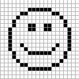
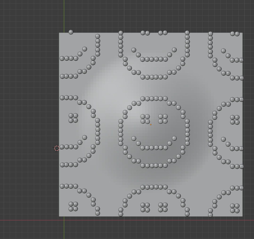
I think it’s not possible right?
(im talking about a true distribution, not an array trick)
2 Likes
Yeah, I don’t think this is really doable at the moment.
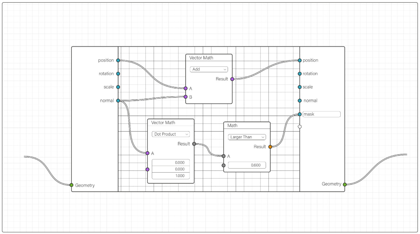
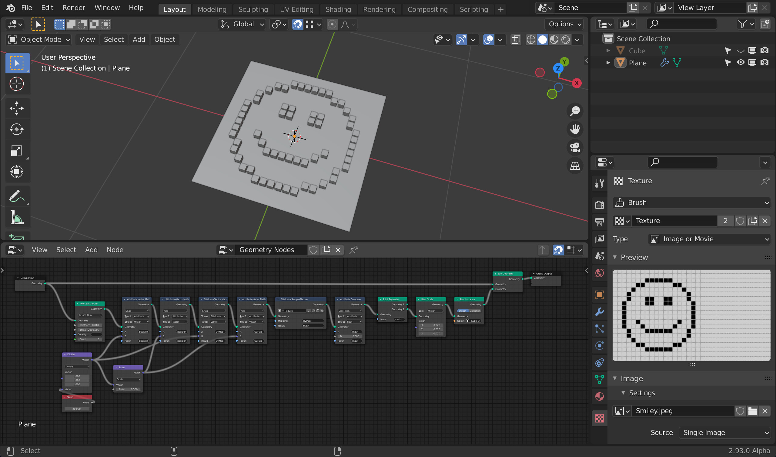
You can constrain the distributed points (and also their UV coordinates) to a ‘pixel grid’ with the Snap operation in the vector Math node, but with the current distribution methods I don’t see a nice way to guarantee that actually every pixel gets exactly one point (You’ll either have holes in your distribution or you’ll have a lot of positions with several points so you’d have to use the Weld modifier to get rid of them.)
1 Like
Yeah, that’s tricky
so it’s indeed not possible
Assuming modifiers works with points ![]()
I hope the devs did consider/ review such distribution possibility, it’s quite a powerful method
I don’t think it really matter so long as it fits the current usage in present time.
The OOPS editor was discontinued but SUPER ahead of its time, and probably makes more sense now then it did then
Old can be smart too ![]()
7 Likes
I still kinda miss the OOPS Schematic view. But I’d want essentially a OOPS scene-graph editor as it’s replacement rather than another viewer.
1 Like
Had a blast putting together a spider with simple maths and a cube to “rig” the legs properly and have them move naturally (definitely not naturally).
I used GN for scattering rocks and trees, as well as the grass and weeds/flowers from Botaniq. For this specific organic scattering method, GN is much nicer to work with than the hair systems we’d use before. Setting up a Dynamic Paint brush to serve as a camera cull like @BD3D has shown worked great as well!
I’m used to the attribute workflow now but we seriously have to break out of that “Geometry” socket. It’s so convenient having everything bundled until you just need to pull one thing out and then it’s impossible. Also, forcing everything through one geometry socket makes the whole tree much too linear. I feel like the node interface could be leveraged more if things were broken down into more manageable, exposed parameters. Convenience is the enemy of freedom ![]()

10 Likes
I don’t think it will help. Collapsing such nodes will make a lot of empty space between them and reading trees more difficult. Placing such nodes close together in collapsed state will make it difficult to read when a node will be uncollapsed.
Probably solution with placing nodes to work with geometry attributes inside node groups will be really more convenient. It has its own disadvantages jumping inside node groups every time to edit attributes what can be quite time consuming. But probably such nodes are really related with more low level of abstraction and should be hidden from main tree.
That’s a really good point. I was thinking maybe of having the node when opened cover things beside it, as in it hovers over everything, but that seems like a scenario where its just asking for people to go “oops I forgot I had nodes there”.
I mean, this is already what I do, I just dislike that making a “reasuable” nodegroup every time, I like the idea of having a specialized “nodegroup” for geonodes like @BD3D said.
Wow texture based displacement is working now!
12 Likes