Geometry Nodes

I got something along the lines working, but I’m very new to this type of procedural system and I feel like this is overly complicated. Also it has a buch of limitations (e.g. it’s not actually using the distance from the empty as I couldn’t get the length of the distance vector or figure out a way to use the square root on the attributes to calculate it myself…) :

Getting actual vector math operations for the attribute math node should help a lot with this kind of stuff!
Also maybe someone, that has a better understanding of this type of system can tell me how to do this more elegantly.

My background’s in architecture so you might guess where most of my procedural modeling experience comes from. Therefore I’m pretty comfortable using low level functions and managing arrays of data in my node graphs.
The concept of having attributes attached to the Geometry is intriguing to me as it could certainly help with some of the pain that is keeping all the data you’re working with in sync. But on this first try it felt pretty cumbersome having to reference the same attributes on each operation.

I’m still learning though and I can see the possibilities of this system exploding with just a few more features getting implemented :slight_smile:

Edit: Just looked into the Vertex Weight Proximity Modifier and reread some of the thread. It seems you can just reference manually created vertex groups like any other attribute. That simplifies the entire setup quite a bit! (And makes it actually do what it’s supposed to!)

7 Likes

Wow, that was quick, thanks!
I have to admit that my current knowledge of the system is waaay lower than many people here, I apologize for that but I still need a lot of tryouts and study…

One thing though I want to say is that I feel attributes like scale, position etc., which are more “general” transformation properties, could be more discoverable: unless I wasn’t following this thread, it would have been almost impossible for me to know that for changing e.g. the scale of the scattered objects I had to write “scale” in the attributes. Now, this is the first time I’m working with procedural modeling and a node-based mograph system, so there is for sure a lot of common knowledge and known terms that I just don’t know for lack of experience, but already having common attributes in the shape of a predefined dropdown menu, instead of knowing what to write, could help a lot for users who never dealt with node-based gemometry systems.
One last idea I want to throw, has it been considered to have scale, position, rotation etc. in the form of actual nodes, instead of attributes to write in the attribute node? Like for example, I want to change the scale with a falloff of a bunch of scattered spheres, I add a scale node where I can connect to the parameters of another object/empty to drive the scale… or, maybe create actual falloff nodes. Sorry if my description is so poor, just trying to make understand what I want to achieve :sweat_smile:!

EDIT:

Yes! I just realized now the only problem though is that, using a vertex group, it relies on the number of vertices, so in the exact moment we put a point distribute node before for having random distribution it doesn’t work anymore

4 Likes

Can you explain to me what this spreadsheet is for?
If I understand correctly, then they are needed to display the result of the work of the GN?
Why can’t you display this in the viewport? Actions with Point cloud, object vertices, edges, polygons, etc., can be displayed in the 3d viewport.
If you need to display the value of some attributes in the 3d viewport, for example Position. The position can be displayed as points or objects on which the attribute is affected.
Rotation and scale cannot be shown as points, they can be shown in the viewport only as objects or primitives of the Empty Arrows type. But it’s better to look at the result of working with geometries. Spreadsheets can help here, but they are not required.
What else cannot be seen in the viewport? For example, various scripts and mathematical equations, which, for some reason, cannot be displayed in the viewport as an effect on points or geometry. Spreadsheets can help here too.
But if it is possible to choose between a visual display in a viewport and a spreadsheet, then 99% of users will choose a visual display of the result.
I am not saying that spreadsheets are unnecessary. They are very much needed by those who need them. Because, most likely, high-level professionals will use spreadsheets, and they will be needed for complex tasks.
I suggest creating two nodes.
The Viewer node, as in the Node Wrangler addon, which can be connected to any place and see the result of influencing the geometry (or points or something else) in the viewport.
And a Spreadsheet Viewer Node, which you can connect to any node and display the result in the Spreadsheet Editor. You can also add the ability for a node to enter a name for the name of the Spreadsheet, which can be selected from a list in the Spreadsheet Editor.

Maybe for extremely simple set ups. But even with just position you are dealing with X,Y,Z positions. A vector3 being displayed above every vertex in the viewport, that is already a lot! With even just a few attributes, rotation, scale etc, you would be looking at:


Spreadsheets are virtually the only way of displaying that much information in a sensical way.

Mind you, it’s not just an ease of use thing. A spreadsheet is often imperative to debug, and this applies as well to simple setups. Say I’m instancing a cone and Suzanne on some points. I use attribute randomize for scale, and attribute compare to separate some points by their scale using greater than 0.5. Some points will be below 0.5, some above. I use this to copy Suzzane to points above 0.5, and the cone for below 0.5. In the viewport, you can see the result without the need of a spreadsheet simply by the distinction between the cones and Suzannes. So you visually understand which point is below or above 0.5.

However if I make the setup more complicated, with a couple more attributes, or simply going through a more complicated process, it can become really hard to tell where what is going to occur, maybe tons of point are getting Suzanne all of a sudden and you aren’t sure why. A glance at the spreadsheet should illuminate the issue, allowing you to fix it. That is a simple example, but in higher end projects, especially production it can be pretty nuts what is going on, making the spreadsheet indispensable.

The good news is that for simple stuff you mostly don’t need it. With my example above you can visually see things without the need for floating information above points, the result of the geometry nodes is often good enough for simple stuff. I understand that perhaps for beginners to this kind of workflow you might want more information in the viewport, but it can get really hairy really fast, and I think it’s cleaner to just deal with the spreadsheet. Mostly all I want to see in the viewport, with no relation to nodes within geometry nodes, is normals, point indices, and maybe face indices.

Pablo has some mockups, which are 100% for what is going into master, they are just mockups, but it looks like they are leaning towards fewer temporary nodes like this. Instead, the mockups use a “eye” button on each node to denote what is the output. When you press the eye button the node highlights with a big blue border easily indicating what is the output:


This negates the need for viewer nodes and feels cleaner to me. Particularly I like how it really cleanly indicates where the final result is coming from, compared to another node purely for output. I think this would also remove the need for the modifier output node. It could also have the node wrangler hotkey of ctrl+shift mouse click to make the node activate the viewer.

Animation nodes does this, but I find it way to small to be super helpful, you have to expand it so much, and this would only be worse in geometry nodes with the addition of attributes. I prefer it as it’s own workspace, which seems to be generally what Pablo has in mind in his mockups:


he is making it as a sub-editor of the geometry nodes workspace as you can see in the blue. This has more room to reasonably see what is going on I think. I just photocopied it into what you might consider a standard setup.

Hope that helps a bit. I’m quiet keen myself on the current direction Pablo has in mind, and the general direction geometry nodes has already.

2 Likes

Actually is a pain see in the viewport only the indices or lenght of the edges. And you can’t see various values for same point.

I’m sorry but I don’t see your proposal as reasonable or realistic. The spreadsheet is the best way to see lists of data.

I was not talking about displaying numbers or data in the viewport. I talked about displaying geometry and objects in the viewport. And I’m not against spreadsheets.

It was very foolish to hope that this project would be able to do something innovative, something interactive, that would have visual handles in the viewport, which could be used to adjust the result obtained in the nodes.
But at least I hoped they could avoid having to manually enter commands into the nodes.

Anyway, thanks for your help and clarification.

I don’t think it’s foolish, gizmos are probably going to be tied to nodes at some point, it’s just much too early. As far as vizualisation goes, I thought you meant colouring geometry with attributes ? Black for zero, white for one, and so on ? That’s one good way to visualize them. Seeing values directly next to vertices in the viewport would be super unwieldy, I reckon.

And hail that “eye icon”, I’d rather have that than a dedicated viewer node. Much faster !

2 Likes

The problem is that this won’t work with distributed points, because of this

it’s a bit weird that the points don’t inherit their emitter attr, not sure if i’m the only one thinking that? any other?

@lone_noel great suggestion with the proximity weight modifier, that really opens up many more possibilities! Couldn’t help myself but to come up with another little demo, that uses the proximity weight to drive the position, scale and rotation of instances. I am still impressed by how fluid the viewport playback is with this all running in realtime on my old laptop :slight_smile:

Project file is in video description.

10 Likes

I agree.

This conversation turned out to be far from where it started.
I don’t need to display Data in the viewport.
Initially, I said that Position, Rotation, Scale attributes are just text, they have no visual feedback. It is not clear where they came from and how they interact with other nodes. I believe the attributes should be in the form of nodes and connect with other nodes with noodles.
But people said I needed a spreadsheet to understand where these attributes came from.
I don’t need a spreadsheet, I need the attributes to be visually noodle-related to other nodes.
If you say these attributes are only 3 out of 500 and it is impossible to make a unique node for each attribute. Then you really need to figure out how to do it with nodess and noodles. Entering attributes manually or selecting from a list will not make them visually related to other nodes.

2 Likes

The thing is we have to consider how much visual complexity is added to a node tree if the attributes’ flow is separated from the geometry flow (if I understand correctly what you mean?)… I reckon if you’re careful about naming (both attributes and nodes that create them), I don’t see that as a potential problem. Maybe I’m not seeing the issue (I’m no FX TD!) but my short time spent with that famous magician I was able to trace back creation of attributes rather easily because the nodes were named accordingly.

(how can a spreadsheet tell the user where an attribute comes from?)

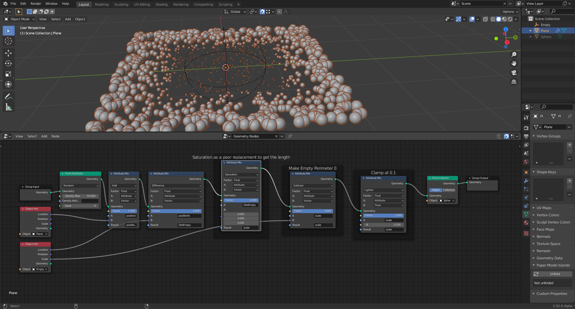
Spent a bit of the last weekend rummaging through Geometry Node tasks, design documents and code. Catching up here. Some provisional and tentative notes that might bemuse and confuse, amuse - or by happenstance, prove useful.

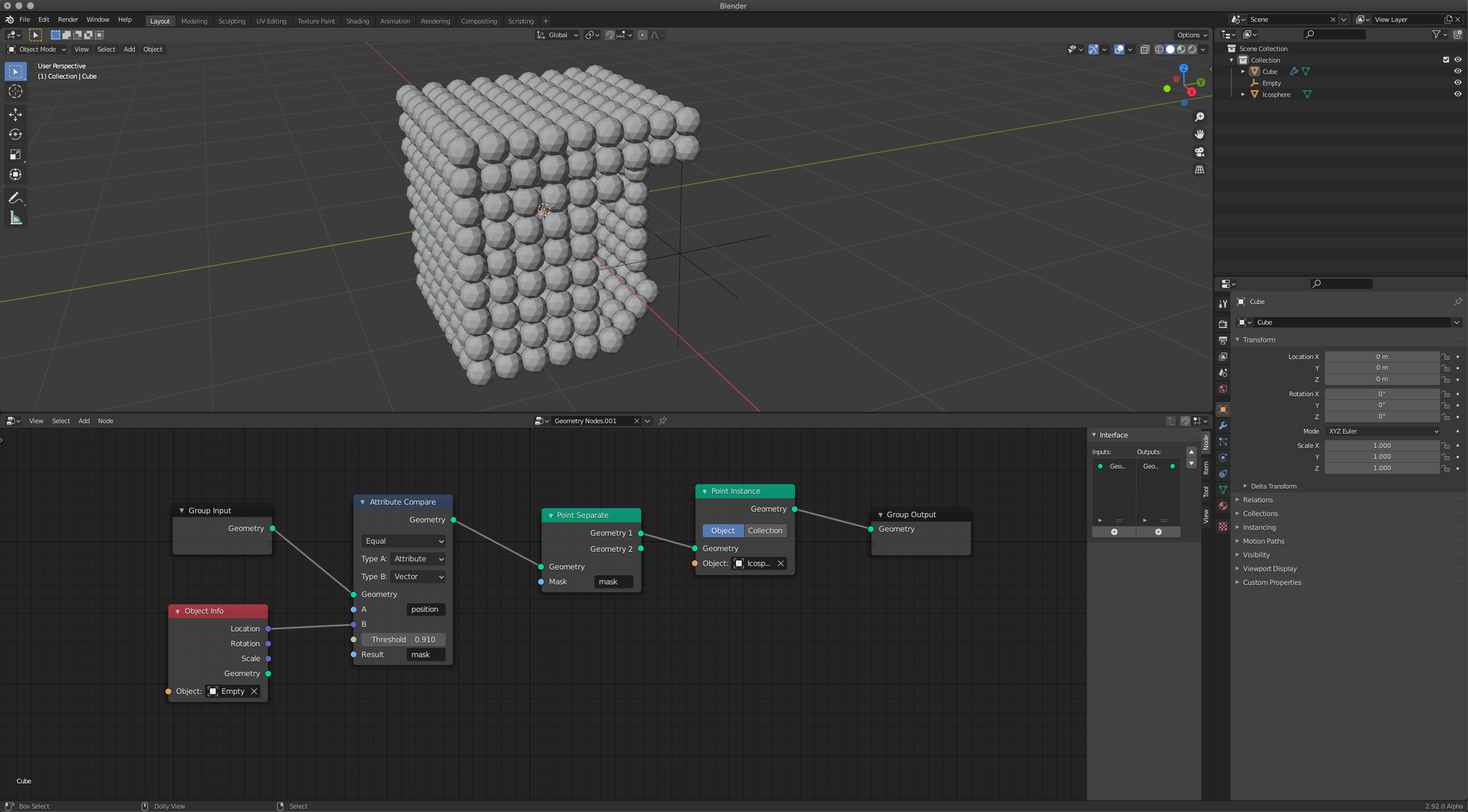
This frame is from an animation inspired by gleanings from @HD3D and @Miro_Horvath posts, upstream from here, and @Miro_Horvath 's Geometry Nodes tutorial, and embodies some of the rummaging I have been doing.

  1. The green box is a VertexWeightProximity modifier target attached to a quad-spherical mesh called QuadBall.
  2. This modifier dynamically generates the weights for a vertex group in QuadBall. The vertex group is called - for no apparent reason - Mileau.
  3. Wherever it passes, the green box produces a ‘cold-spot’ in Mileau.
  4. The pink point-cloud population rather likes the cold spot; the blue’s would rather be elsewhere.

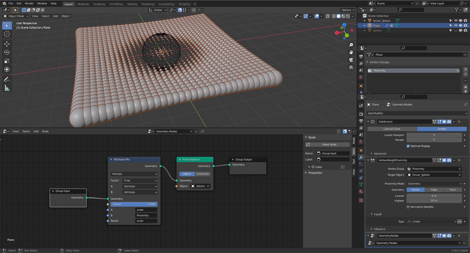
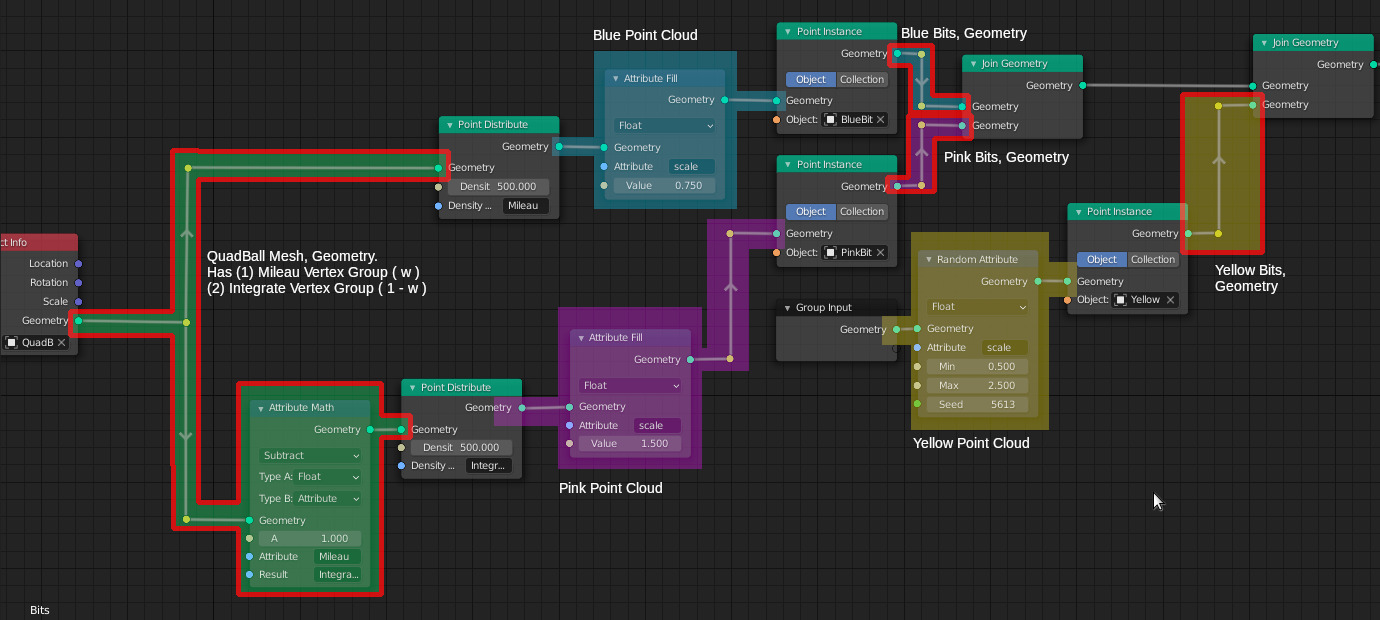
Here’s the geometry node tree promoting this behavior.

To my way of thinking, some nodes partition the geometry node tree into distinct regions - scopes[^3]. Just one geometry set[^1] prevails in that scope. I annotated the geometry node tree to reflect some of the scopes.

Geometry sets mirror Blender objects and some may be injected into the node tree from specific Blender object antecedents (Group Input imports the geometry of the object under modification; Object Info imports the geometry of a named (mesh) object).

Geometry sets are invisible, lurking behind the scenes of geometry node trees. They prevail in exactly one scope. Just one input or transforming node injects a single geometry set into a scope, which establishes the scope’s prevailing ‘type’ (mesh, point cloud, voxel…). Any number of nodes can read the geometry set in a scope. Geometry sets, like attributes, aren’t visualized. I painted various scopes in my geometry node tree to note their existence.

At the intersect of neighboring scopes one invariably finds a transformer node like Distribute Points. By ‘transformer’ I mean something which reads geometry set on its input Geometry socket and outputs another geometry set to its output[^4]. For example,Distribute Points reads mesh geometry sets and writes point clouds. Transformers do some kind of transitive work. Rainy Day Notes suggests a breakpoint for those inclined to spelunk through a probability calculator, one characterizing the transitive work of Distribute Points.

I now slap myself on the hand when I find myself thinking that geometry sets flow through the geometry node tree. They don’t. They are anchored in scopes. Some node may read a geometry set in one scope and output into another scope a (possibly only loosely related) geometry set.

Attributes[^2] also live in one scope only. Essentially, an attribute is a list of floats or vectors whose items are in one-to-one correspondence with the items composing one of the geometry set’s domains. It takes use of an attribute node to endow this correspondence with meaning. Attribute nodes variously generate randomized lists (Attribute Randomize), fill attributes entries with a value (Attribute Fill), engage two attributes in simple math-or-mix operations (Attribute Math and Attribute Mix).

Like geometry sets, they are also (nearly) invisible. Attributes[^5] vex because they tightly link with the prevailing geometry set of the scope - indeed, they link with specific domains[^1], though, at present, only point-like domains are supported: point clouds or mesh vertices. With attributes, all we have are names. We conjure up attributes by only citing them as operands in attribute nodes.

Being tightly linked with geometry sets in specific scopes, they cannot directly operate in other scopes. Giving attributes the same name in different scopes does not create ‘data wormholes’ among scopes. Identically named attributes in different scopes are mutually invisible to each other and do not interact.

To my mind, a class of (currently hypothetical) ‘attribute transform nodes’ would have to be implemented to interpolate an attribute in one scope to a corresponding attribute in another scope. For example it would be pleasantly convenient for some Normal Transfer node to read a face-normal attribute list (in the polygon domain) from a mesh geometry set - a fixed list in one-to-one correspondence with mesh’s faces - and interpolate it into a directional field attribute for a mesh-instanced point cloud geometry set in another (not necessarily neighboring) scope. Then we would have some hope of aligning instanced point cloud items with a locally prevailing direction, which might align with the originating mesh’s normals - or not, if other attribute nodes in the destination scope come into play and artistically mess with the direction field.

All that said, this is how I read this geometry node tree:

  1. Scope 1: The QuadBall mesh geometry set prevails.
  • Maps to the Blender mesh object QuadBall; An Object Info node injects this mesh geometry set into the scope.
  • The geometry set has two intrinsic float-type attributes, Mileau and Integrate, another meaninglessly named vertex group. Each attribute list weights from its respective, identically named, vertex group.
  • An Attribute Math node connects Mileau to Integrate: Mileau's (w) become Integrate's (1 - w).
  • Two Point Distribute nodes read Scope 1’s mesh geometry set. Each of these transformers generate new point clouds, each in different scopes.
  1. Scope 2: Blue point cloud geometry set prevails.
  • Injected into the scope by a Point Distribute node, this ‘blue’ point cloud geometry set actually bears no relation to the ‘native’ point cloud summoned into existence at the creation of the Bits point cloud Blender object. The ‘native’ point cloud may be injected into some other scope by the Group In node - or not, as many of you have left it dangling. See Scope 4. The ‘blue’ point cloud geometry set came into being through a probability calculator embedded in Point Distribute nodes. That calculator infers a ‘probability density field’ based on the area of triangulated polygon faces, available from the mesh geometry set in Scope 1, the weight attribute Mileau, the Density parameter given by the user, and a temporary, random float attribute to furnish a 'flip-of-a-coin.
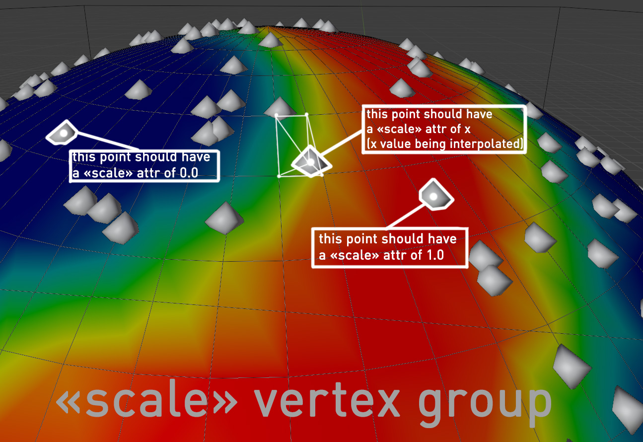
  • An Attribute Fill node populates an internal geometry set attribute called scale. Its elements are keyed to all the pointcloud points. There is an implied multiplication when using this attribute, setting the size of pointcloud points.
  1. Scope 3: This scope mirrors Scope 2, differing in only in given parameters.
  2. Scope 4: Yellow point cloud geometry set prevails.
  • Injected into the scope by the modifier’s Group In node, this point cloud is independent of all the other point clouds. This put paid to a notion I once had that a Point Distribute node took a point cloud and flowed it onto a mesh. No. Not really. Every Point Distribute calculates a new point cloud geometry set; these point cloud geometry sets exist in different scopes. I suppose one could call this the ‘factory default’ point cloud geometry set.
  1. Remaining Scopes: transform point cloud geometry sets with mesh instances.

I think that the isolation among scopes is neither a good or bad thing, technically, but much of the frustration that I felt was a general lack of means to port information native to one scope into another. I can’t give instance clouds information about the mesh they’ve been distributed across - not directional fields, not interpolated weights. I think these are temporary limitations reflecting that much about geometry nodes still needs to be built. I’m very impressed how many of you have risen above these limitations and made visually exciting animations nonetheless. I hope these notes are useful, but caution that they are provisional - sort of like the early maps of the world. Take care; have fun.


Rainy Day Notes
[^1] geometry set: In my thinking, a mapping of a Blender object which also similarly types the geometry set.

  • As there are different kinds of Blender objects, geometry sets are of different types and possess internal organizations reflecting their allied Blender objects.
  • A geometry set mapped from a Blender mesh object features distinct vertex, edge, corner and polygon domains, ordered lists in one-to-one correspondence to their Blender mesh object compeers.
    [^2] Attributes are named ordered lists that associate extra data to items in one of a geometry set’s domains. The items of extra data are also in a one-to-one correspondence to the allied domain items.
  • Attributes may appear as part of a geometry set’s mapping to an allied Blender object. For example, attributes named after mesh object vertex groups mirror the weights of the vertex group.
  • Attributes may also spring into existence just by being named in one of the slots of an Attribute node (Attribute Randomize, Attribute Mix, Attribute Fill, Attribute Math)
    [^3] In my thinking, a scope has at most one prevailing geometry set, emerging from some Group In or Object Info Geometry output (‘right hand’) socket. No other output socket can inject a competing geometry set into a scope. However, the input Geometry sockets of any number of nodes can read the prevailing geometry set in the scope.
    [^4] Group Input, Group Output, Object Info, Point Distribute and Point Instance nodes separate and delimit scopes.
  • My mind resists the idea that geometry sets ‘flow through’ such nodes. Rather, such nodes look like transformers, reading geometry sets at their left-hand Geometry input sockets, doing some characteristic processing, then creating new (and possibly differently typed) geometry sets at their right-hand Geometry output sockets.
    ++ Code spelunkers so inclined may wish to set a breakpoint at scatter_points_from_mesh() in source/blender/nodes/geometry/nodes/node_geo_point_distribute.cc The behavior I observe is transformer-like: it derives a brand new point cloud geometry set based (maybe loosely) on the input mesh geometry set.
    ++ To trigger the breakpoint, leave the Geometry input socket of a Point Distribute node disconnected in a test Blender file that has an otherwise complete geometry node tree. Save, start your favorite debugger with a suitable debug executable, set the breakpoint and run. Connecting the node to an output Geometry node that sources mesh geometry sets triggers the breakpoint.
    [^5] Attributes appear resticted to their scope and are permanently keyed to the prevailing geometry set of that scope.
  • Naming identically two attributes, each in different scopes, does not seem to create ‘linked attributes’. Instead, the two attributes are distinct and unrelated, apparently invisible to one another. That seems consistent with the idea that the two scopes have prevailing geometry sets that are likely of different ‘type.’ Seeing that attributes are so-keyed to geometry sets, they are intrinsically incompatible with geometry sets in different scopes.
  • Since they appear restricted to their ‘home’ scope, this invites contemplating a class of transformer-like attribute nodes that perform the necessary scaling/interpolation so that information contained in an attribute in a source geometry set can create a compatible attribute in the destination geometry set prevalent in a foreign scope. If we think of face normals being an polygon domain attribute of mesh geometry sets an apt attribute transformer node could create a direction field attribute for mesh-instanced point cloud geometry sets. Then we can effectively align these instances with the prevailing normal direction.
5 Likes

I think that making combo nodes, loses the philosophy of making small and simple nodes that you combine little by little to add modular complexity. It is much easier to understand a system of nodes if they are small and simple steps joined together than complex nodes that combine functions. Here I leave my example mockup with the current design and my proposal.

Actual:

Proposal:

I think it is much more intuitive to read my proposal step by step than to use combo nodes that are not clear about where you are using the attribute of whom.

23 Likes

I agree with @zebus3d

His proposal can be encapsulated into the container done that was going to be developed, but the readibility is way better, right now, too much functionality on each base node it’s bad and goes against the idea of having low level nodes, and high level containers, and right now it feels like the focus is put into high level nodes, instead of containers.

Right now it feels very hard to do for example a simple boolean check to enable ro disable the effect of a float input, of course there are many things that are not there yet, like array handling or looping, but I´m afraid, after plying with it, that some nodes are getting too much complexity instead of being kept as simple nodes, and made complex with high level “container” nodes, they are basically black boxes, that´s not good for the general idea and philosophy of the nodes project IMHO

4 Likes

I fully agree. That is a lot easier to read.

3 Likes

I haven’t tried geometry nodes that much yet. But at a glance, your proposal is much more clear to me how the data flows and gets combined.

2 Likes

Again, attributes are a data payload that is inseparable from the geometry. While your proposal is easier to look at at a glance it overlooks that those attribute arrays that have been retrieved by the get attribute node will have likely been invalidated by an intermediate operation on the geometry.

Hence: What happens when you do this? Everything is broken now…

5 Likes

In Sorcar, when the user tries to do things that are supposed to give error or break things and don’t work, the nodes are put in red to alert the user that what he is doing is wrong and can’t be done.
83959846-83a33880-a89f-11ea-9b1d-651b32541316
the node, or all conflicting nodes in the meantime, is cancelled.

1 Like

But that is literally creating an error every time the topology of the input of the first get attribute doesn’t match the add attribute node. Users are going to get frustrated by this. It would be better to encapsulate complex attribute math in a attribute wrangler network or something.

The same in Animation Nodes, you get a warning and the tree cannot be executed.