Spent a bit of the last weekend rummaging through Geometry Node tasks, design documents and code. Catching up here. Some provisional and tentative notes that might bemuse and confuse, amuse - or by happenstance, prove useful.
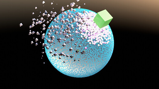
This frame is from an animation inspired by gleanings from @HD3D and @Miro_Horvath posts, upstream from here, and @Miro_Horvath 's Geometry Nodes tutorial, and embodies some of the rummaging I have been doing.
- The green box is a VertexWeightProximity modifier target attached to a quad-spherical mesh called
QuadBall. - This modifier dynamically generates the weights for a vertex group in
QuadBall. The vertex group is called - for no apparent reason -Mileau. - Wherever it passes, the green box produces a ‘cold-spot’ in
Mileau. - The pink point-cloud population rather likes the cold spot; the blue’s would rather be elsewhere.
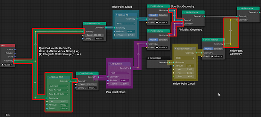
Here’s the geometry node tree promoting this behavior.
To my way of thinking, some nodes partition the geometry node tree into distinct regions - scopes[^3]. Just one geometry set[^1] prevails in that scope. I annotated the geometry node tree to reflect some of the scopes.
Geometry sets mirror Blender objects and some may be injected into the node tree from specific Blender object antecedents (Group Input imports the geometry of the object under modification; Object Info imports the geometry of a named (mesh) object).
Geometry sets are invisible, lurking behind the scenes of geometry node trees. They prevail in exactly one scope. Just one input or transforming node injects a single geometry set into a scope, which establishes the scope’s prevailing ‘type’ (mesh, point cloud, voxel…). Any number of nodes can read the geometry set in a scope. Geometry sets, like attributes, aren’t visualized. I painted various scopes in my geometry node tree to note their existence.
At the intersect of neighboring scopes one invariably finds a transformer node like Distribute Points. By ‘transformer’ I mean something which reads geometry set on its input Geometry socket and outputs another geometry set to its output[^4]. For example,Distribute Points reads mesh geometry sets and writes point clouds. Transformers do some kind of transitive work. Rainy Day Notes suggests a breakpoint for those inclined to spelunk through a probability calculator, one characterizing the transitive work of Distribute Points.
I now slap myself on the hand when I find myself thinking that geometry sets flow through the geometry node tree. They don’t. They are anchored in scopes. Some node may read a geometry set in one scope and output into another scope a (possibly only loosely related) geometry set.
Attributes[^2] also live in one scope only. Essentially, an attribute is a list of floats or vectors whose items are in one-to-one correspondence with the items composing one of the geometry set’s domains. It takes use of an attribute node to endow this correspondence with meaning. Attribute nodes variously generate randomized lists (Attribute Randomize), fill attributes entries with a value (Attribute Fill), engage two attributes in simple math-or-mix operations (Attribute Math and Attribute Mix).
Like geometry sets, they are also (nearly) invisible. Attributes[^5] vex because they tightly link with the prevailing geometry set of the scope - indeed, they link with specific domains[^1], though, at present, only point-like domains are supported: point clouds or mesh vertices. With attributes, all we have are names. We conjure up attributes by only citing them as operands in attribute nodes.
Being tightly linked with geometry sets in specific scopes, they cannot directly operate in other scopes. Giving attributes the same name in different scopes does not create ‘data wormholes’ among scopes. Identically named attributes in different scopes are mutually invisible to each other and do not interact.
To my mind, a class of (currently hypothetical) ‘attribute transform nodes’ would have to be implemented to interpolate an attribute in one scope to a corresponding attribute in another scope. For example it would be pleasantly convenient for some Normal Transfer node to read a face-normal attribute list (in the polygon domain) from a mesh geometry set - a fixed list in one-to-one correspondence with mesh’s faces - and interpolate it into a directional field attribute for a mesh-instanced point cloud geometry set in another (not necessarily neighboring) scope. Then we would have some hope of aligning instanced point cloud items with a locally prevailing direction, which might align with the originating mesh’s normals - or not, if other attribute nodes in the destination scope come into play and artistically mess with the direction field.
All that said, this is how I read this geometry node tree:
- Scope 1: The
QuadBallmesh geometry set prevails.
- Maps to the Blender mesh object
QuadBall; AnObject Infonode injects this mesh geometry set into the scope. - The geometry set has two intrinsic float-type attributes,
MileauandIntegrate, another meaninglessly named vertex group. Each attribute list weights from its respective, identically named, vertex group. - An
Attribute Mathnode connectsMileautoIntegrate:Mileau's(w) becomeIntegrate's(1 - w). - Two
Point Distributenodes read Scope 1’s mesh geometry set. Each of these transformers generate new point clouds, each in different scopes.
- Scope 2:
Bluepoint cloud geometry set prevails.
- Injected into the scope by a
Point Distributenode, this ‘blue’ point cloud geometry set actually bears no relation to the ‘native’ point cloud summoned into existence at the creation of theBitspoint cloud Blender object. The ‘native’ point cloud may be injected into some other scope by theGroup Innode - or not, as many of you have left it dangling. See Scope 4. The ‘blue’ point cloud geometry set came into being through a probability calculator embedded inPoint Distributenodes. That calculator infers a ‘probability density field’ based on the area of triangulated polygon faces, available from the mesh geometry set in Scope 1, the weight attributeMileau, theDensityparameter given by the user, and a temporary, random float attribute to furnish a 'flip-of-a-coin. - An
Attribute Fillnode populates an internal geometry set attribute calledscale.Its elements are keyed to all the pointcloud points. There is an implied multiplication when using this attribute, setting the size of pointcloud points.
- Scope 3: This scope mirrors Scope 2, differing in only in given parameters.
- Scope 4:
Yellowpoint cloud geometry set prevails.
- Injected into the scope by the modifier’s
Group Innode, this point cloud is independent of all the other point clouds. This put paid to a notion I once had that aPoint Distributenode took a point cloud and flowed it onto a mesh. No. Not really. EveryPoint Distributecalculates a new point cloud geometry set; these point cloud geometry sets exist in different scopes. I suppose one could call this the ‘factory default’ point cloud geometry set.
- Remaining Scopes: transform point cloud geometry sets with mesh instances.
I think that the isolation among scopes is neither a good or bad thing, technically, but much of the frustration that I felt was a general lack of means to port information native to one scope into another. I can’t give instance clouds information about the mesh they’ve been distributed across - not directional fields, not interpolated weights. I think these are temporary limitations reflecting that much about geometry nodes still needs to be built. I’m very impressed how many of you have risen above these limitations and made visually exciting animations nonetheless. I hope these notes are useful, but caution that they are provisional - sort of like the early maps of the world. Take care; have fun.
Rainy Day Notes
[^1] geometry set: In my thinking, a mapping of a Blender object which also similarly types the geometry set.
- As there are different kinds of Blender objects, geometry sets are of different types and possess internal organizations reflecting their allied Blender objects.
- A geometry set mapped from a Blender mesh object features distinct vertex, edge, corner and polygon domains, ordered lists in one-to-one correspondence to their Blender mesh object compeers.
[^2] Attributes are named ordered lists that associate extra data to items in one of a geometry set’s domains. The items of extra data are also in a one-to-one correspondence to the allied domain items. - Attributes may appear as part of a geometry set’s mapping to an allied Blender object. For example, attributes named after mesh object vertex groups mirror the weights of the vertex group.
- Attributes may also spring into existence just by being named in one of the slots of an Attribute node (
Attribute Randomize,Attribute Mix,Attribute Fill,Attribute Math)
[^3] In my thinking, a scope has at most one prevailing geometry set, emerging from someGroup InorObject InfoGeometry output (‘right hand’) socket. No other output socket can inject a competing geometry set into a scope. However, the input Geometry sockets of any number of nodes can read the prevailing geometry set in the scope.
[^4]Group Input,Group Output,Object Info,Point DistributeandPoint Instancenodes separate and delimit scopes. - My mind resists the idea that geometry sets ‘flow through’ such nodes. Rather, such nodes look like transformers, reading geometry sets at their left-hand Geometry input sockets, doing some characteristic processing, then creating new (and possibly differently typed) geometry sets at their right-hand Geometry output sockets.
++ Code spelunkers so inclined may wish to set a breakpoint atscatter_points_from_mesh()insource/blender/nodes/geometry/nodes/node_geo_point_distribute.ccThe behavior I observe is transformer-like: it derives a brand new point cloud geometry set based (maybe loosely) on the input mesh geometry set.
++ To trigger the breakpoint, leave the Geometry input socket of aPoint Distributenode disconnected in a test Blender file that has an otherwise complete geometry node tree. Save, start your favorite debugger with a suitable debug executable, set the breakpoint and run. Connecting the node to an output Geometry node that sources mesh geometry sets triggers the breakpoint.
[^5] Attributes appear resticted to their scope and are permanently keyed to the prevailing geometry set of that scope. - Naming identically two attributes, each in different scopes, does not seem to create ‘linked attributes’. Instead, the two attributes are distinct and unrelated, apparently invisible to one another. That seems consistent with the idea that the two scopes have prevailing geometry sets that are likely of different ‘type.’ Seeing that attributes are so-keyed to geometry sets, they are intrinsically incompatible with geometry sets in different scopes.
- Since they appear restricted to their ‘home’ scope, this invites contemplating a class of transformer-like attribute nodes that perform the necessary scaling/interpolation so that information contained in an attribute in a source geometry set can create a compatible attribute in the destination geometry set prevalent in a foreign scope. If we think of face normals being an polygon domain attribute of mesh geometry sets an apt attribute transformer node could create a direction field attribute for mesh-instanced point cloud geometry sets. Then we can effectively align these instances with the prevailing normal direction.

