Rigid Body Simulation in Geometry Nodes
This is an experimental branch for testing rigid body simulation in geometry nodes. The general idea is to present rigid bodies, constraints, and other parts of the simulation as domain data with attributes, similar to other kinds of geometry.
Test branch can be found here: https://projects.blender.org/blender/blender/pulls/124093
This approach is quite different from an earlier test i made, which was a lot more object-based. That branch relied on a common physics world between objects, which requires complicated depsgraph relations to make sure geometry can synchronize with the physics world.
The new code is completely separate from existing Bullet integration in Blender. All aspects of the simulation are handled inside a new GeometryComponent, which keeps the code nicely compartmentalized and does not require substantial changes to existing geometry code.
Demo
What the system can do at this point:
- Create rigid bodies, collision shapes, and constraints as elements in the physics component.
- Advance the simulation by time steps.
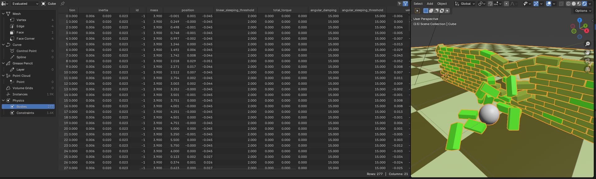
- Access properties of rigid bodies and constraints as attributes of the physics component.
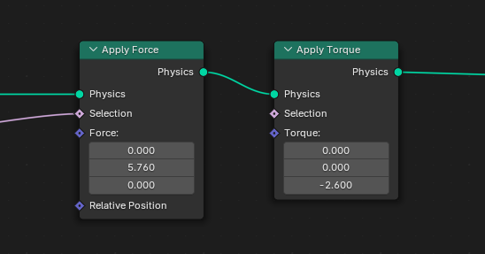
- Add forces, torque, and other effects dynamically.
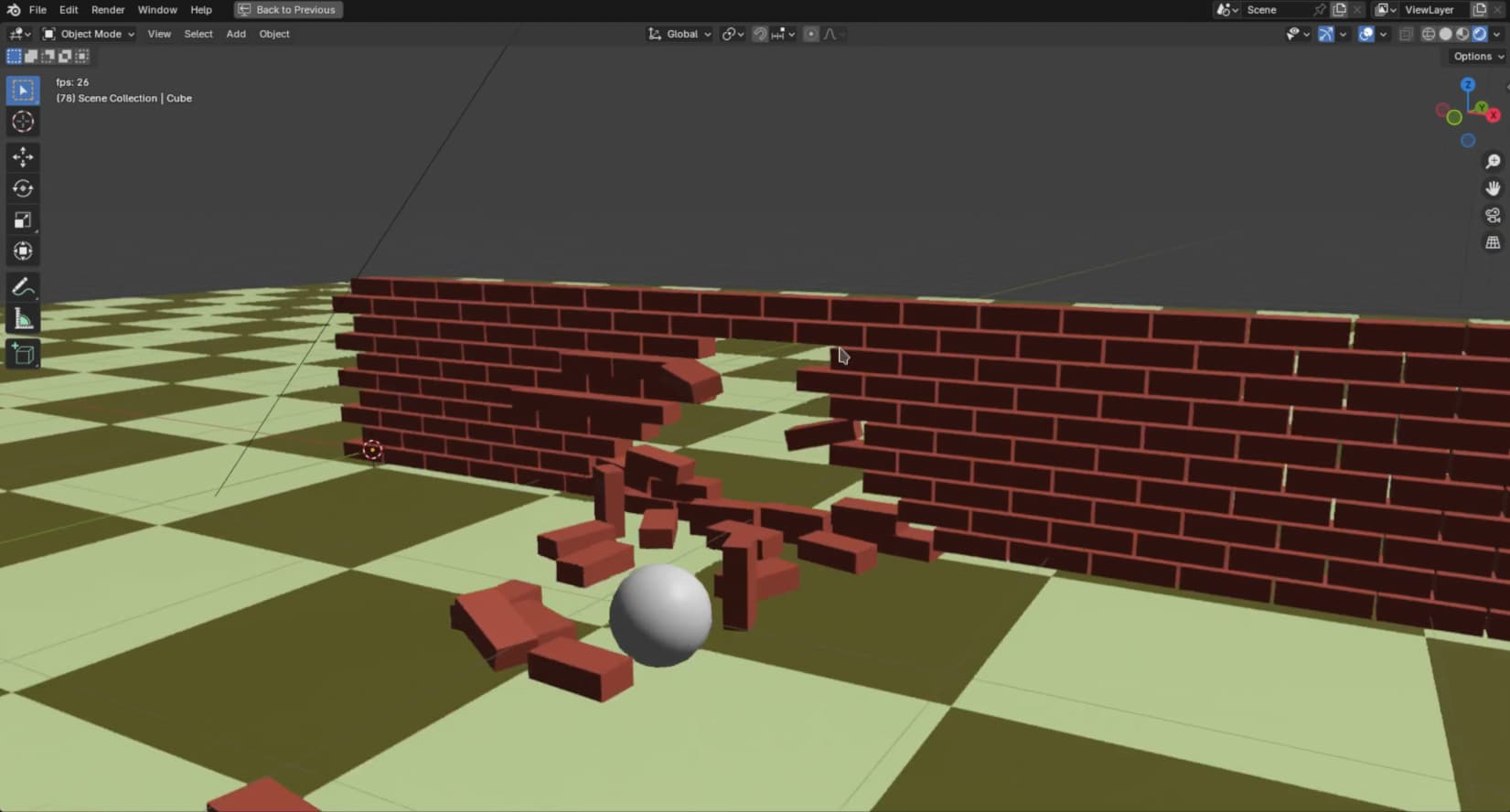
Here’s a test of a cannonball hitting a brick wall. It’s using breakable constraints of each body to the world, which get activated by the collision.
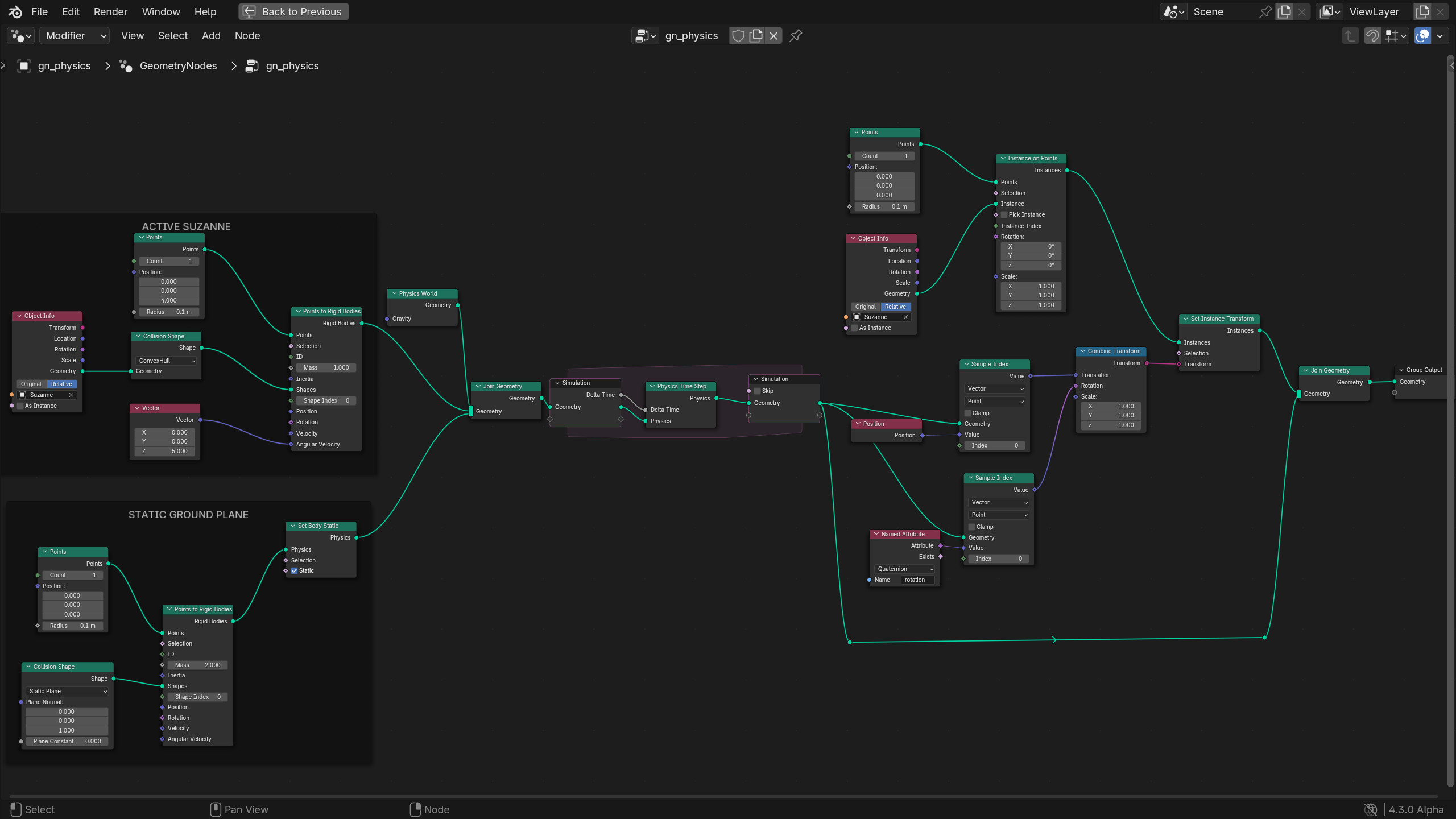
How it works
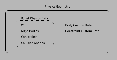
All the physics data lives inside the geometry set, rather than a separate physics world inside the scene. Bodies and constraints are associated with the Point and Edge domains of the geometry respectively (dedicated domains for
bodies and constraints may be added later).
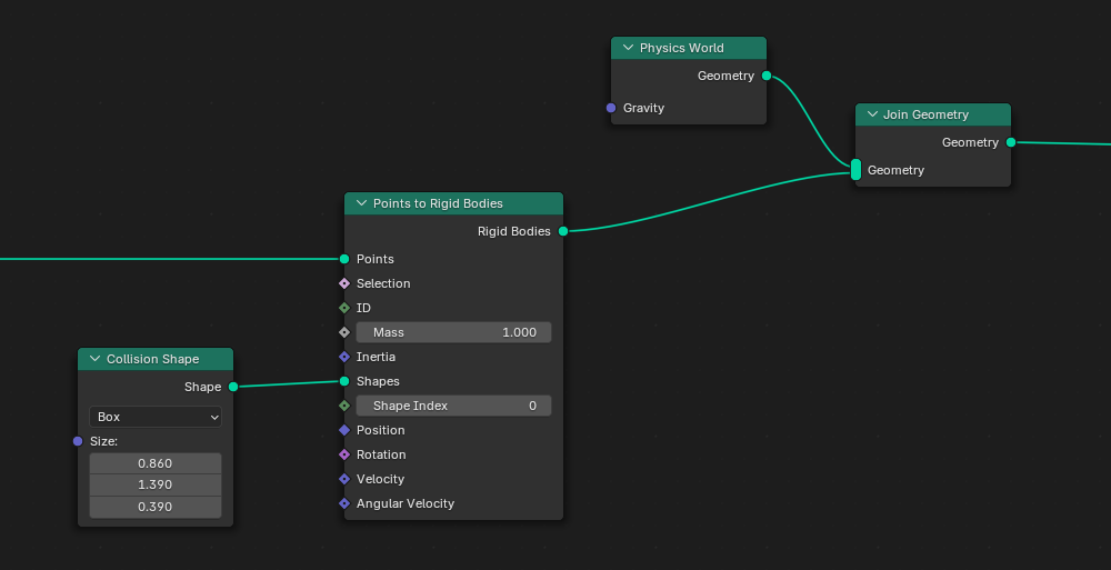
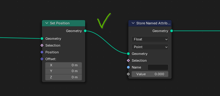
The geometry component can also store a physics world that is responsible for the actual simulation data. It’s ok to have bodies and constraints without a physics world in a component; this is usefull for creating bodies separately and then adding them into an existing world using a Join Geometry node.
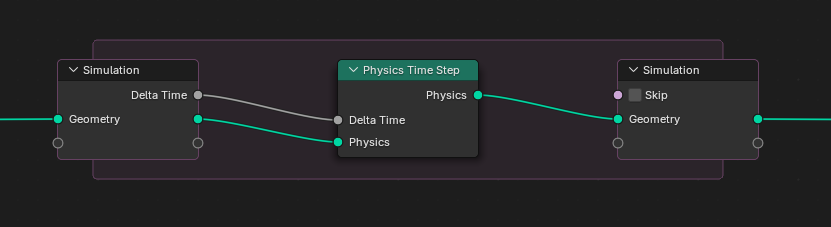
Time-stepping the simulation happens with a simple “Time Step” node. This can be used in a Simulation Zone for conventional physics simulation within the scene timeline. It could also be used as a standalone node, e.g. for one-off collision detection. It could also be used in a Repeat Zone to execute a fixed number of simulation steps all at once, e.g. for a physics-based node tool.
The component defines a set of built-in attributes for the properties of rigid bodies. This ranges from basics like mass, position, velocity to more specialized features like rolling friction, sleeping thresholds and more. These properties of the underlying physics implementation (Bullet engine for the time being). To users they show up as attributes in the spreadsheet and can be accessed using existing techniques.
In addition to built-in attributes that map to the Bullet btRigidBody instances there is also CustomData for bodies and constraints. This enables dynamic attributes associated with those domains.
Constraints are described in the edge domain, because they connect two rigid bodies each, which resembles the topology of an edge-mesh. Target bodies are identified by simple index attributes (pointers are used internally). Adding or removing bodies will automatically remap those indices. Constraints also function with only one valid body (index -1), in which case it gets constraint to a fixed point in object space.
Technical Challenges
There are some aspects of the design that require more attention.
No Copying of Physics Data
The physics world internally holds a lot of additional state for bodies, like broadphase pair caches, active contacts, and more. For this reason doing full copies of rigid bodies and re-inserting them into the world is not great for performance (and actively discouraged by the Bullet API).
The conventional data flow in geometry nodes leads to copies of data frequently being made (mostly optimized out by using implicit sharing):
-
Node output geometries are copied to linked node inputs. During the copy the component is usually immutable (2 concurrent users), but in simple pass-through chains becomes mutable again when the next node in the chain is executed.
-
Branching creates 2 permanent users of the geometry component, which makes a copy necessary. This applies even in “simple”, branches like Viewer nodes, where one branch is read-only.
-
Realizing instances makes a copy of the input data. This is of course correct for actually realizing instances but is also used in the case of joining geometries: the input geometries are copied, merged, and then the original data is released.
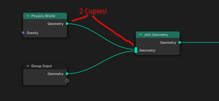
In the cases mentioned above additional copies of the physics data would be costly and technically unnecessary: the physics data is usually moved from one node to the next, adding and removing bodies, advancing the simulation, etc. To ensure physics data is never actually copied the component uses the following concepts:
-
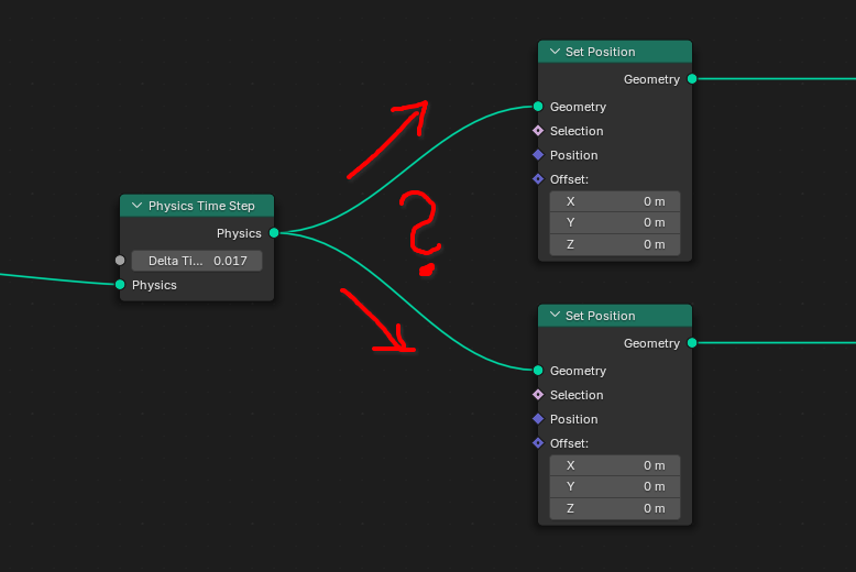
Physics data gets moved rather than copied when making it mutable.
This means only the first copy has “real” physics data. Any subsequent copies will not be able to do simulation. This violates the design of geometry nodes somewhat, which treats all copies as equal. Which copy is “first” can be random, so node trees need to be constructed very carefully to avoid ambiguity.
-
Physics data is cached after moving.
When physics data is stolen by another geometry, the source will use a cache to provide read-only data. In this state the physics component becomes basically a point cloud with simple attributes.
While the system works as-is, a more robust and predictable solution is needed here.
Constraint Types
All constraints are treated equally as part of the Edge domain. Constraints are usually categorized by type (ball-and-socket, hinge, slider, cone-twist, etc.). This type is superficial: constraints can be described in terms of the generic 6DoF constraint, the type just makes it easier to understand the purpose and behavior of a constraint.
The constraint type attribute exists, but is read-only. Changing constraint types can be done with a special create_constraints function, but not by simply writing to an attribute. Since enums are not supported as attributes the constraint type is currently a plain integer, which is far from ideal. A node could be added to “translate” this value into something meaningful.
Customization
Conventional workflows for setting up physics are based around defining assets, then inserting them into the physics world for simulation, and finally transfer data back to the original object. While this can be implemented to some degree with the “realize instances” mechanism, it only works for relatively simple objects where properties don’t change after the simulation has started.
More complex simulations require, for example, effectors that react to scene conditions, change strength based on animation, and much more. These kinds of features require deep integration into the simulation nodes, so that the nodes coding the behavior can be executed as part of the time step. This makes it hard to build extensible systems that could be extended without touching the simulation itself.
This kind of problem is not unique to physics simulation and will come up in other areas. Some ideas have been proposed to “inject” node graphs into existing node setups, but it’s not a trivial problem.
Future additions
Some ideas for things to add:
-
Drawing for physics components
This would be useful for debugging purposes to get a quick impression of the state of the physics world. Currently a complicated setup for transferring data to visible instances or similar is needed to view the placement of rigid bodies. Physics data should not show up in renders directly, but displaying a viewport representation is necessary.
-
Contact point output
Getting information about contact points between rigid bodies could be extremely powerful. This can be a simple point cloud that encodes current contacts and their state. Since contacts are essentially just temporary constraints they might also be included in the constraint/edge domain (but harder to distinguish from user-defined constraints).
-
Collision triggers
Physics shapes can also be used purely for collision detection, without any direct dynamic response. This can provide a feedback mechanism to trigger custom behavior.