Really interesting.
Similarly we have the redo panel to handle these changes.
But a visual return of these values in the gizmo itself could also be helpful.
No high priority though.

thinking …
@Howard_Trickey is working on an improved boolean system.
you @mano-wii are working on a better selection system
that can expand snapping tools and precise modeling …
Now that there are active tools, I think you should start offering some tools that can edit objects even in object mode.
like the bevel, or the extrusion of “surfaces” together with the Boolean operations …
to do this you really need little … a selector as active tool of entire segments and “surface faces areas” … as some tools already offer …
updates:
New Snap Option Middle
https://developer.blender.org/rB58341242bf6b30392435130b242d2366ab03c1dd
New Snap Option: Edge Perpendicular
https://developer.blender.org/rBdd08d68df835e54ccd1fdf24ae154e461faab685
in work in progress:
Use a more descriptive snap element drawing
https://developer.blender.org/D5546
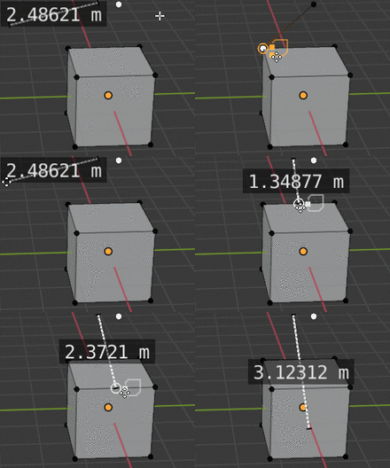
Is that automatically contextually finding the most proper snapping method? Wow!
it’s just mixed snapping - he activated more than one method in the dropdown menu.
the gif instead shows a proposal of how the user would know what is it being snapped atm - with showing the icons beside it
Will the new snapping methods be more suited for retopology as well? I read in the design task for retopology that Blender needed a better snapping method for that type of work. Are these related in some way?
Not entirely, this is a separate task - however I believe Germano is going to be working on the retopo task as well. The new snapping in question is supposed to project elements along their axis of transformation, like a shrinkwrap does, instead of projecting them along the view vector. Basically, move them until they hit some surface. That should allow for wrapping tubular meshes onto character arms, for instance - right now face snapping does not work for this as it tries to project the vertices along the view vector.
in review:
Snapping System: Improve drawing indicating Perpendicular snap
https://developer.blender.org/D5557
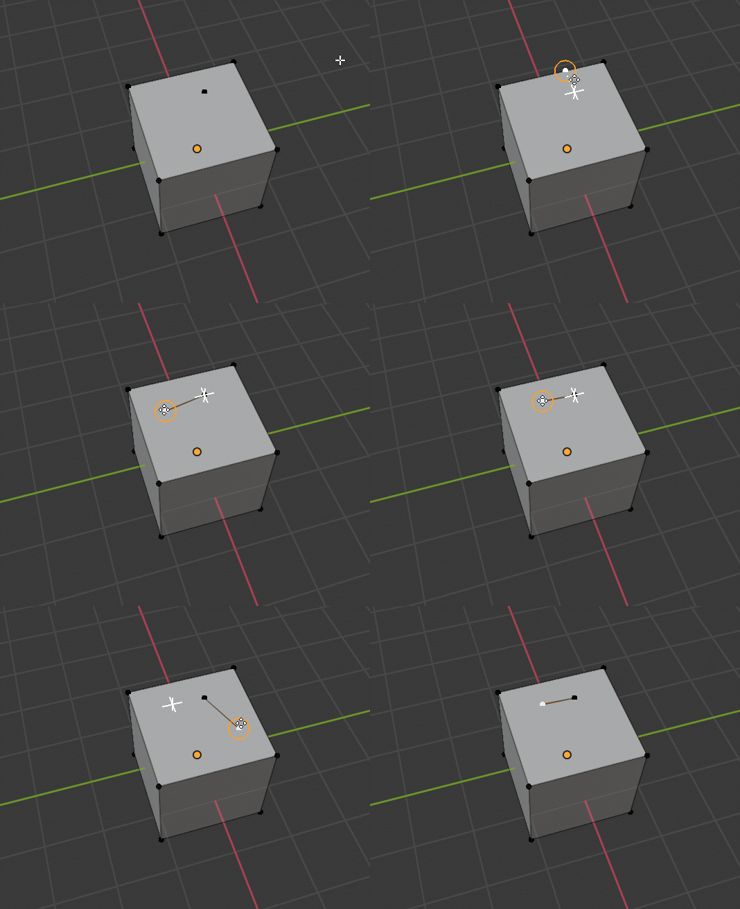
if I’m not mistaken about retopology we were working both William Reynish and Pablo Dobarro
it seems quite obvious that all snapping improvements will be available in retopology mode
Hello guys. I would like to post this proposal inside the discussion.
This is about some additional snapping indicators for blender.
Thanks.
guys, here is sooner or later what “snapping tools” I’d like to see for mesh elements and objects …
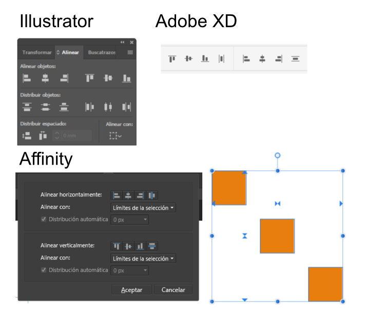
place a screenshot of inkscape, so you already know what it is …
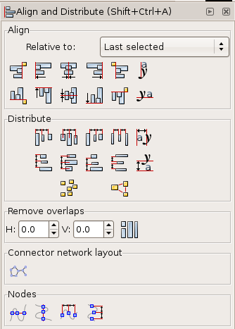
These are super noisy, I’ve tried to use inkscape multiple times and the first thing I always did was changing the icons. The ones in Illustrator for distribute look good, but I always click the ones that shouldn’t be clicked. Affinity icons for distribute are better and they’re used in similar apps like Figma as well as adobe XD ironically.
Turns out they don’t have the other two options for distribute that’s why they can use other icons.
Affinity also has an align toolbox right when you select the objects (optional), very intuituve.
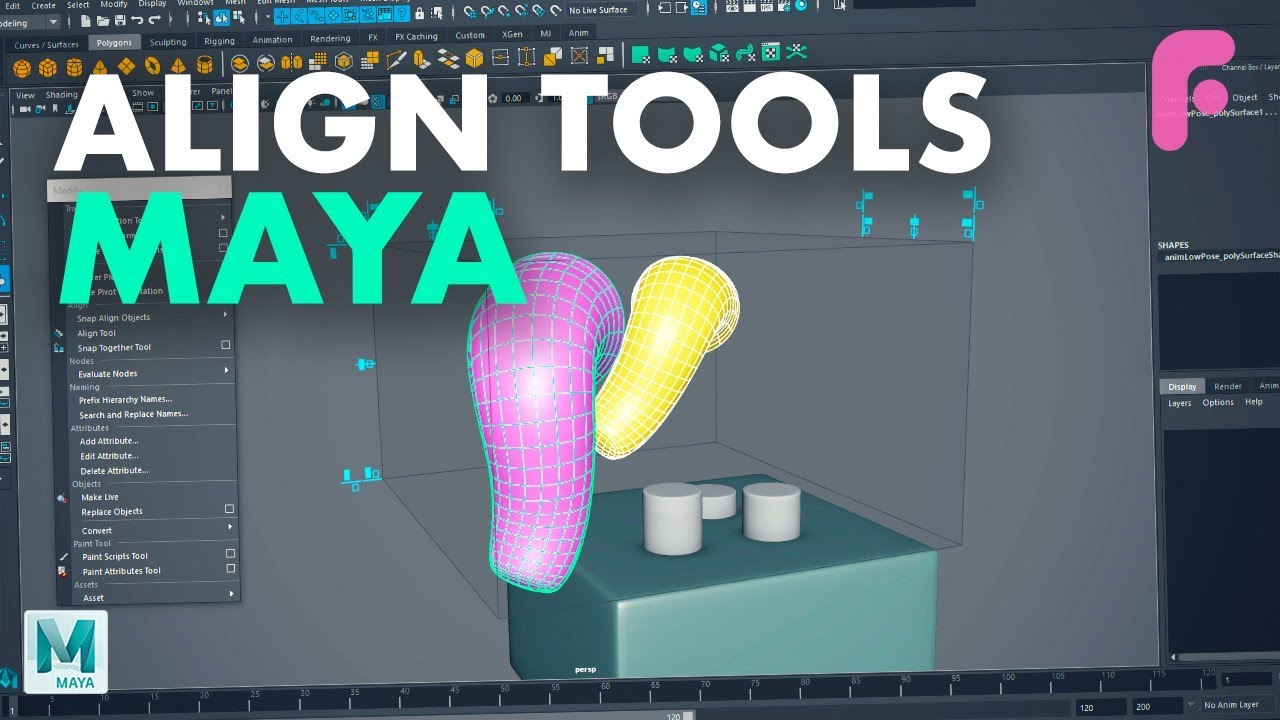
This reminds me to what maya does as well, which is how we should do it (Starts at 6:32 but you can see it in the thumbnail already)
I used inkscape just to make the idea … ![]()
obviously in blender if all this comes, everything will be better …
we have iconologist killer machines here ^ __ ^
same reflection analysis :
with the new tools of retopology mode, and with the expansion of scuplting tools, it is clear that the classic edit mode modeling must grow especially in its potential for precision modeling and snapping which is obviously the part where it is potentially most used.Pablo Dobarro Poly build tool improvements
https://developer.blender.org/D5573
@mano-wii
another thing that should be corrected is to allow snapping on the intersection points of the measurement tools, and obviously, the measurement objects should not disappear while we move the vertices …
edit:
speaking of measuring instruments , here are some suggestions that emerge at the moment:
I have already read some of your interesting suggestions, such as transforming rulers into a new type of object called “measurement objects”
For this purpose it is necessary that the measuring tool is improved, the current defects must be removed, such as the appearance and disappearance of them if you enter object mode or mesh mode, or select another object … for this reason we need that the measurement outputs are objects that can be viewed in the outliner and that can then be hidden, freezed, rendered … like all other outiliner objects …
I would like the snapping points to work also on the measuring instruments … for convenience …
Another thing I’d like to suggest is that blender can create measurement objects automatically measuring by selecting entire segments (even curved) corners etc …
Then I would suggest the creation of APIs for devs that will want to add custom symbols for the various project categories, where addon developers can create their set of visual objects, for example the electronics has its own set of symbols, archviz have their symbols etc …
My initial thoughts are that we already have a good start in MeasureIt (now shipped with Blender), although there are some issues there to resolve. It does a lot of what we want, but I would like to see some improvements. I am not convinced at all by the current “Measure” tools in Blender, because they do not dimension properly, or in accordance with accepted draughting standards and they disappear too often!
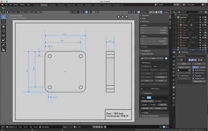
I show this image as a quick “What you can do” with MeasureIt, it also shows that the lines are too long in most cases and I had to work some Clock Magic™ to get the gaps between the object and the dimension lines:
The good thing is that MeasureIt will render these dimensions to an image, but you then have to Alpha-Over them onto the rendered image of the object using Compositor - not a huge headache, but it would be better if Blender just rendered them to start with. I used an orthographic camera for this to get a proper test render, this one above is just a screen render.
I am tempted, if you all agree, to make a new thread for this requirement - a “Let’s Add Dimensions to Blender” thread, which you can start @nokipaike and I will enthusiastically add my thoughts to. the correct term for this is “Dimensioning” not “Measuring” in my humble opinion, we should adopt this, if you all agree and I will contribute all my knowledge to it, being a past draughtsman, both on a board before CAD was invented and subsequently. ![]()
This 2D drawing was produced with only Blender, MeasureIt and my own PDT tools. I got the line drawing by using Wireframe Modifiers and some “tweaking” - we still have a way to go to get this kind of output easily and intuitively, rather than by magic and lateral thinking.
Cheers, Clock. ![]()
OK, I feel like I should “shake the hornet’s nest” a little. Whilst I agree with all the comments and proposals to improve snapping, by this I presume we all mean that the chosen vertex, or object, or vertices will go somewhere useful when we start moving, or extruding things, I am also of the opinion that we need to be able to place the cursor at useful locations prior to a process being initiated.
From my experience, it can be far more productive to place the cursor exactly where you want it then do something, rather than always rely on all the snapping tools to move things during a process, or create something then move /rotate it where you want it. I would like to be able to tell Blender where I want the cursor, by keying absolute, delta, or directional information through a simple system of cursor placement. I do not want to have to key values, tab between X, Y & Z and input sine, cosine and tangent functions to imitate directional vectors, having previously clicked = to get advanced input mode - such an awkward system when keying I2.3,27 could mean 2.3 units at 27 degrees in view plane, or D1,5,3 could mean delta 1 in X, 5 in Y and 3 in Z from existing location & A1.2,5,2.5 could mean absolute, or global coordinates. I could use these key-ins to move the cursor, move objects/vertices, or extrude geometry, etc.
The ability to “snap” or cursor locate to the midpoint along an edge is nice, but why not use a fraction, or percentage instead and why not be able to use two unconnected vertices rather than just an edge? After all midpoint is a very limited example of the more universal percentage and 50% is still the midpoint, even in these days of poor mathematical attainment by school children… (I qualify this remark by asking how many understand calculus by the age of 15?, how many know how to calculate pi by age of 13? etc. etc.). then there are intersections, including normal (perpendicular if you prefer) and planar intersections of converging lines, either physical from edges, or implied from vertices.
Also, we need to be inclusive of all genres of CAD users, including Mechanical Engineers, Electrical Engineers, Architects, Civil Engineers, etc. etc. I notice that a lot of work issuing done and targeted at specific genres, whereas its would have better appeal if all this “CAD” stuff was targeted across the board. To this end we also need “Parts Libraries” designed similar to Pose Libraries, but with geometry in them, like standard electronic parts for circuit board designers, as a simple example.
We also need to “pool” our ideas into a single source to avoid duplication of effort…
Let’s see how many hornets get p***ed off with the nest shaking. The broader the appeal of this work, the more likely it is to get into Blender, unless the Devs disagree…
Cheers, Clock. 
for this reason I proposed the creation of generic API sets so the addon’s developers can have fun with customizations in this sense …
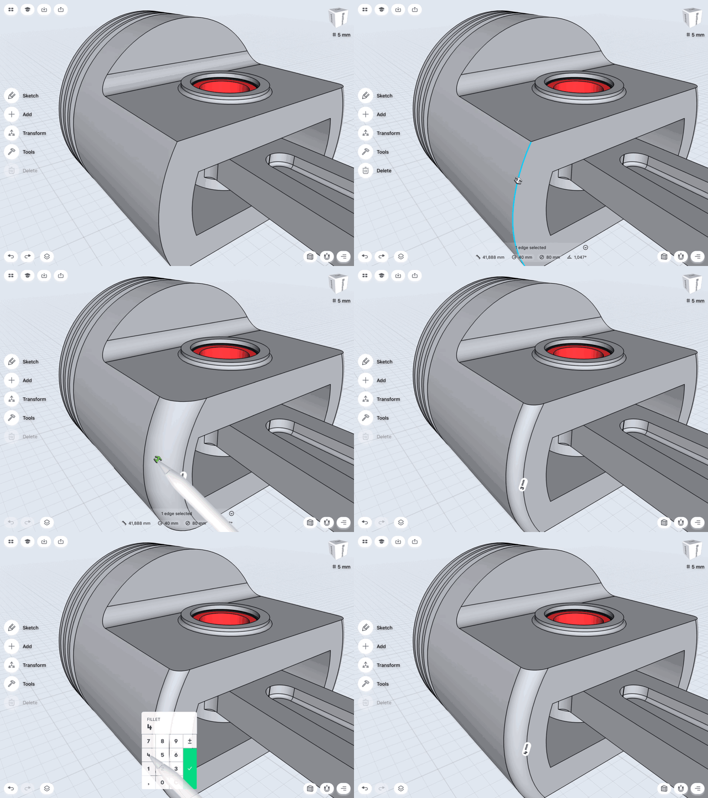
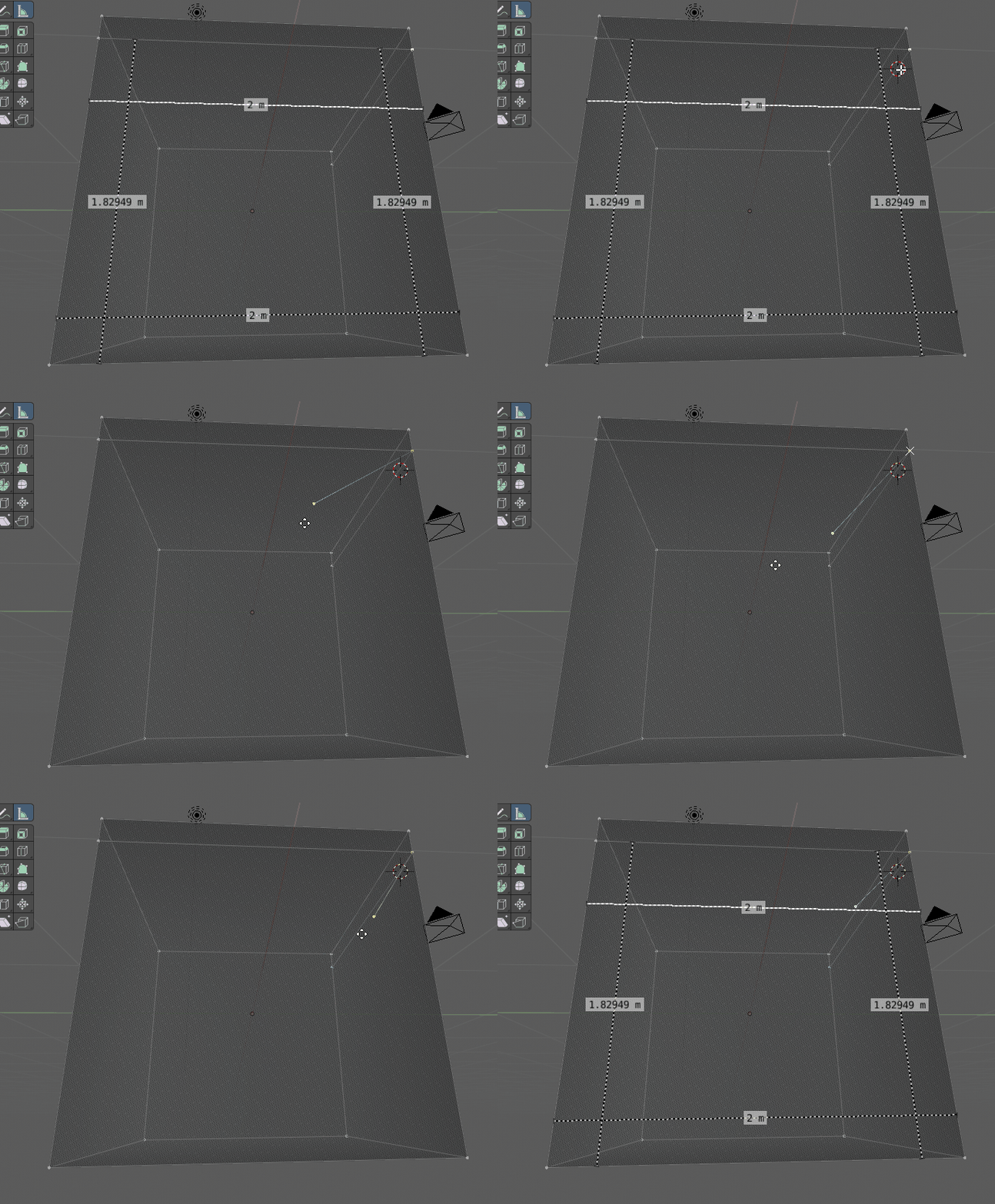
speaking of visual helpers - dimensions tool, here’s how other software behave …
