It would be amazing if we could get a snap along normals option when snapping to faces. Right now, as I’m sure you know, snapping to faces only works on faces facing the camera.
(Vertices snapped at a different angle than the screenshot)
It would be amazing if we could get a snap along normals option when snapping to faces. Right now, as I’m sure you know, snapping to faces only works on faces facing the camera.
something like this would save a lot of time ( adding and applying shwringwrap for retopo takes a lot of time and its not precise, it also can’t be apply to instances, different issue yes) and open a field for proper re topology tools, for example combining this with the relax brush of Dobarro’s sculpt branch would be extremely useful for retopo.
Yes, here is the option on my CAD Functions node - needs working into Blender, done with Numpy Arrays, moves the cursor for now, same maths would be used for snapping.
I Edge:
2 Vertices, unconnected:
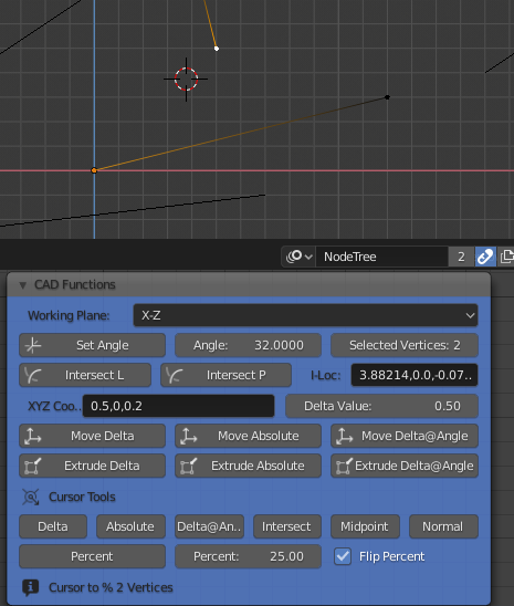
2 Vertices, unconnected - flipped percentage.
Cheers, Clock. ![]()
@clockmender did you see?
it’s nice how the project started to accelerate to the point where Ton decided to make it stand out among the core tools.
These things always fascinate me.
I am literally seduced by this form of Social Engineering which emerged with blender and this devtalk forum 
No I didn’t - where should I look? ![]()
Speaking of Dobarro’s Relax tool and retopology, it would be super nice if that tool was available in Edit Mode. Been trying to use the Smooth Brush to make my retopology not so clumped together kind of like how Maya does it with its own relax geometry tool for retopology, but it’s not the same.
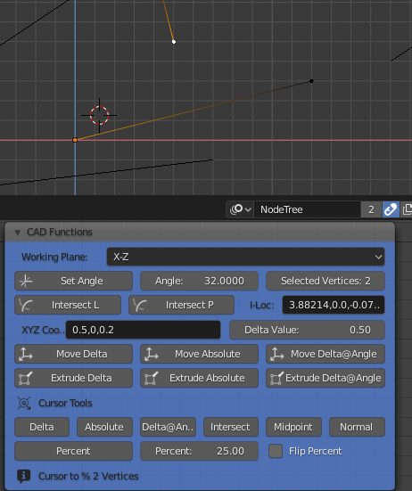
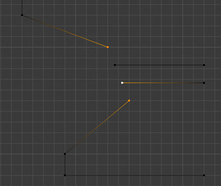
So, I looked at another issue - that of moving a vertex to a percentage distance between two others:
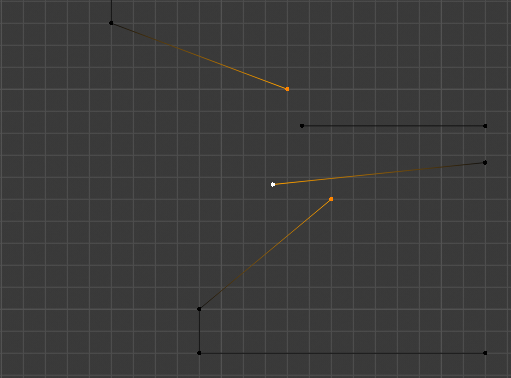
In this one you would select the vertices as “first two are the location ones, third is the one to move”, set the percentage and click the button, here is the result:
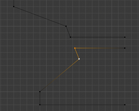
The vertices are now 1/3 of the distance between the two outer vertices. Next we would like to join two free vertices:
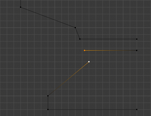
I know you can use J, but this does not join free vertices, only those in a face. Here is the result:
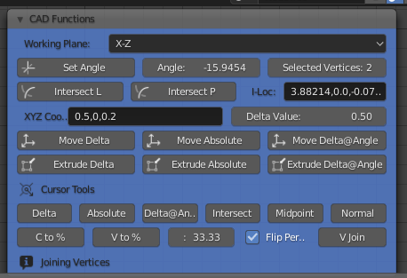
To get to 1/3rd distance; I typed 100/3 into the Percentage box as I could not remember what a third of 100 is. ![]() So you can type anything in here, like 700/8, 1200/39, etc. Here is the node now:
So you can type anything in here, like 700/8, 1200/39, etc. Here is the node now:
Maybe I should get on with writing the spec for all these CAD functions now…
Cheers, Clock. ![]()
Or just type in 1/3, 2/3 etc. How dumb of me  , this doesn’t make sense in with what you were showing. I probably was thinking of something else entirely. Haha
 Great work btw, I hope all if not most of these functions can make it into vanilla blender someday.
You can achieve the same transform in stock Blender by adding two snap points to the vert you want it to be closer to. It takes a bit of thinking when you want to move it by a percentage that isn’t easily expressed as a fraction, but it’s serviceable in most situations.
I couldn’t get this to work, but I have Snap Utilities, which I’m very happy with. Are you putting the Modal Map changes under the Press (Cursor) or Release (Transform)? How are your other snap settings set?
Modal maps aren’t unique to the keymap entry; add 'em wherever. In the video, I’ve set my pivot to Cursor, toggled snapping on, set the snap element to Vertex, and the snap target to Center.
What is the proposed behaviour for the case where I have a plane and I am cutting with the knife tool and I am using grid snapping and the plane does not intersect with the grid exactly? Would the vertex be cut so that it superimposes the grid based on view or would the newly created vertex snap to the exact grid point?
@Gooney - Welcome to the forum!
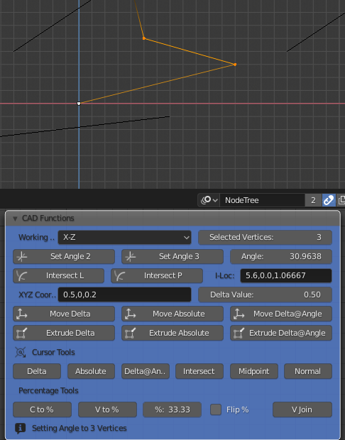
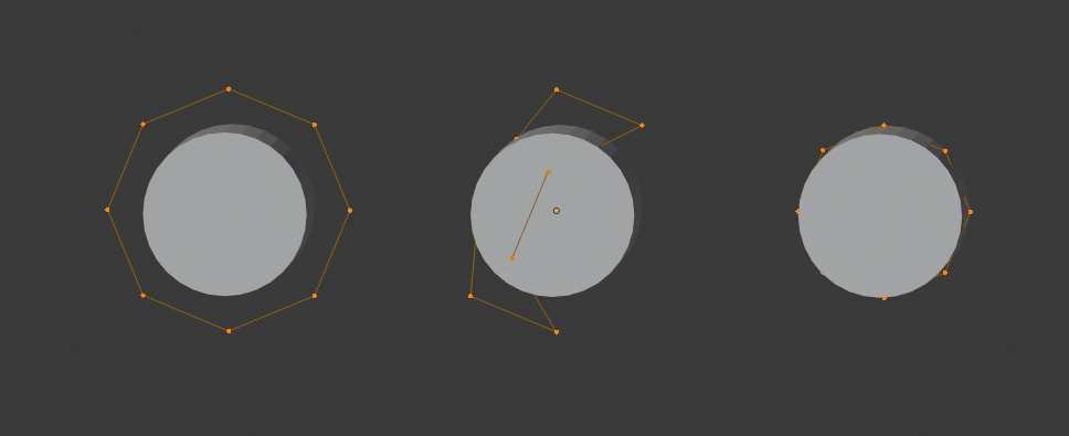
I added a new “Set Angle” option whereby you select three vertices, the last one (active vertex) being the centre and the other two being the “legs”:
That then sets the node’s working angle to the angle between these three points, this works in 3D, taking into account all three axes of the vertices. It’s done with Numpy Arrays again so should translate easily to vanilla Blender.
If anyone wants to look at my crap ![]() code, or test the node, let me know and I will upload it to my GitHub, Caveat Emptor of course, this is experimental code!
code, or test the node, let me know and I will upload it to my GitHub, Caveat Emptor of course, this is experimental code!
I have also modified the code so it takes into account the actual position of an object if it is parented to another and moved from its original origin.
I am still working on my spec for CAD functions, this could take some time to get right.
Cheers, Clock. ![]()
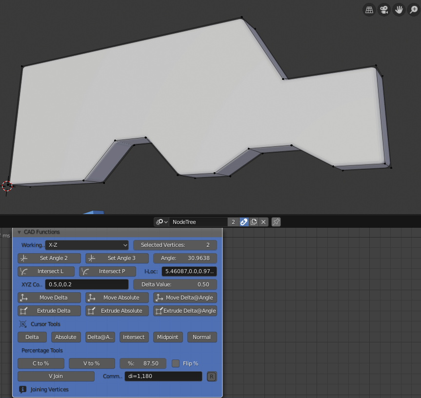
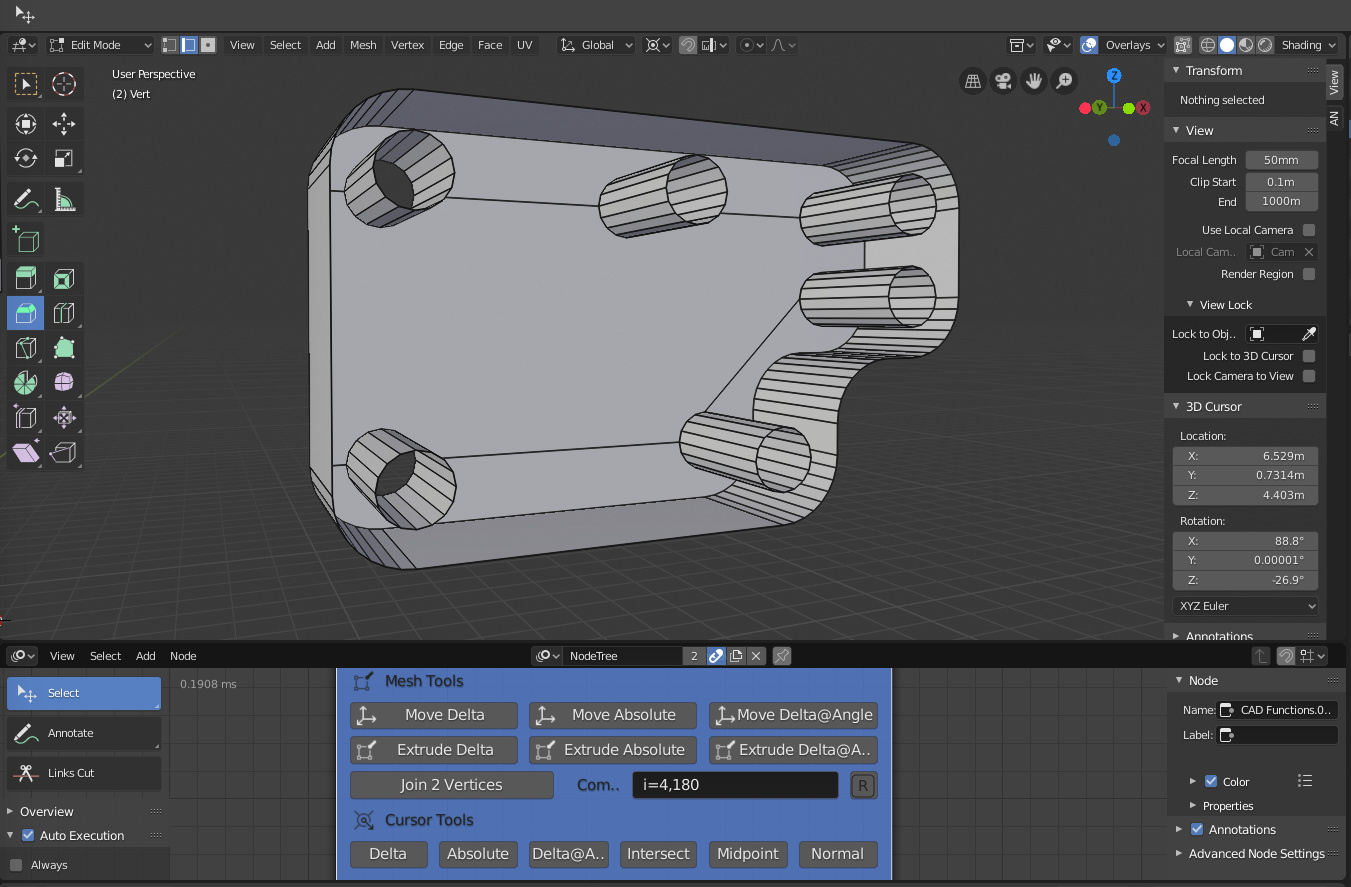
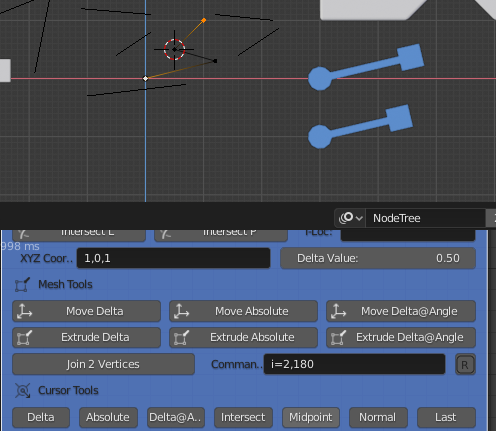
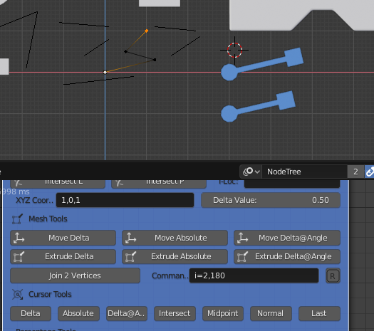
On the matter of precision CAD modelling, I have added test function to the node:
The section at the bottom allows me to join free vertices, add a command key-in and execute the command. The shape above was drawn very quickly using this facility.
I started with a vertex placed randomly, then used “Move to Absolute” to move it to a known XYZ coordinate. I then extruded it using the commands, like di=1,35 (distance at angle), dx=0.5,0,0.5 (delta distance), etc until the shape was formed. Then I closed the chain from the first to last vertex using the “V Join” option.
From there onwards its just a case of selecting the edge loop (SHIFT+ALT+Select), then key F to make the chain a face, then extrude in Y axis (E Y 0.2). This method of construction was fast, logical, precise and easy. It will be even easier once these commands can be executed as key-ins in vanilla Blender. I will need to find letters, preferably single ones, that are not already in use, like perhaps; e.g. a=0,0,0 for absolute, e.g. d=0.5,0.0.6 for deltas and e.g. i=0.5,30 for distance at angle, maybe even leave out unrequired items, so; e.g. d=,,0.5 would mean delta 0.5 in Z axis.
I am not 100% sure what letters are not currently being used when you extrude a vertex, maybe the = sign is not required, so a 1,0,2 would work even better. To work in Local units, as opposed to Global, we could adopt dd 0.5,,0.5 to mean delta 0.5 in local X, 0 in local Y and 0.5 in local Z, for example.
Any thoughts on this please?
Cheers, Clock. ![]()
EDIT:
I was able to make this part quickly, easily and precisely using the CAD tools, I made the outside shape first, then extruded this, then beveled the corners. I use my cursor tools to place the cursor for adding the holes. Then used the “Join 2 Vertices” to add the “cut” edges to make the three faces on the back:
I have left off the front faces to show the internal detail. This view shows how the “Cursor Normal” tool was used to place the cursor at the correct centre for the lower hole:
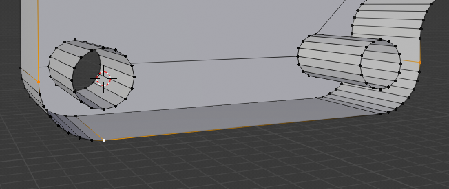
The two yellow vertices are used to define the “edge” and the white one was used to make the normal offset.
I have added a “Cursor Last” option to put the cursor back to its last known position before it was moved by any of the commands on the node. Before (placed Midpoint):
After (its original position before the “Mid Point”):
This should definitely be in vanilla Blender, how many times do we accidentally move the cursor, having spent time putting it where we want it? I implemented this with a dictionary, so I can store the cursor location for all scenes, only the last value at the moment, but this can easily be changed to say the last ten positions for example.
Cheers, Clock. ![]()
I hope the measure tool gets some love…
along those lines:
Have you considered submitting your suggestion on https://blender.community/c/rightclickselect/ ?
@TheRedWaxPolice your video does not work for me, is there somewhere else I might find it please?
Reviewing my old proposals in RightClickSelect, I found this
that I think can partially fit into this project.
It consists in improving the 3D cursor so that apart from position i the orientation also provides information about a length, an angle and a plane.
Clicking and dragging can generate a line, and splitting a line in half can generate an angle, which defines a plane.
With the current Active Measurement Tool, this can be done exactly, but only provides information that can be used to transform the objects.
As I explain in the RightClickSelect proposal, apart from aligning and distributing, it has other applications.
I hope it can be useful.
My dream would be to have a visual preview that in evanescence follows the radius of the mouse cursor and shows the snapping points, the axes, the midpoints, the tangent points, the perspective points, the measures etc … in some similar to how Moi 3D does …
It would save the need to have a lot of menu changes, and at most a filter would be needed.