@brecht thanks for the guidance, I think I have the importance sampling working now.
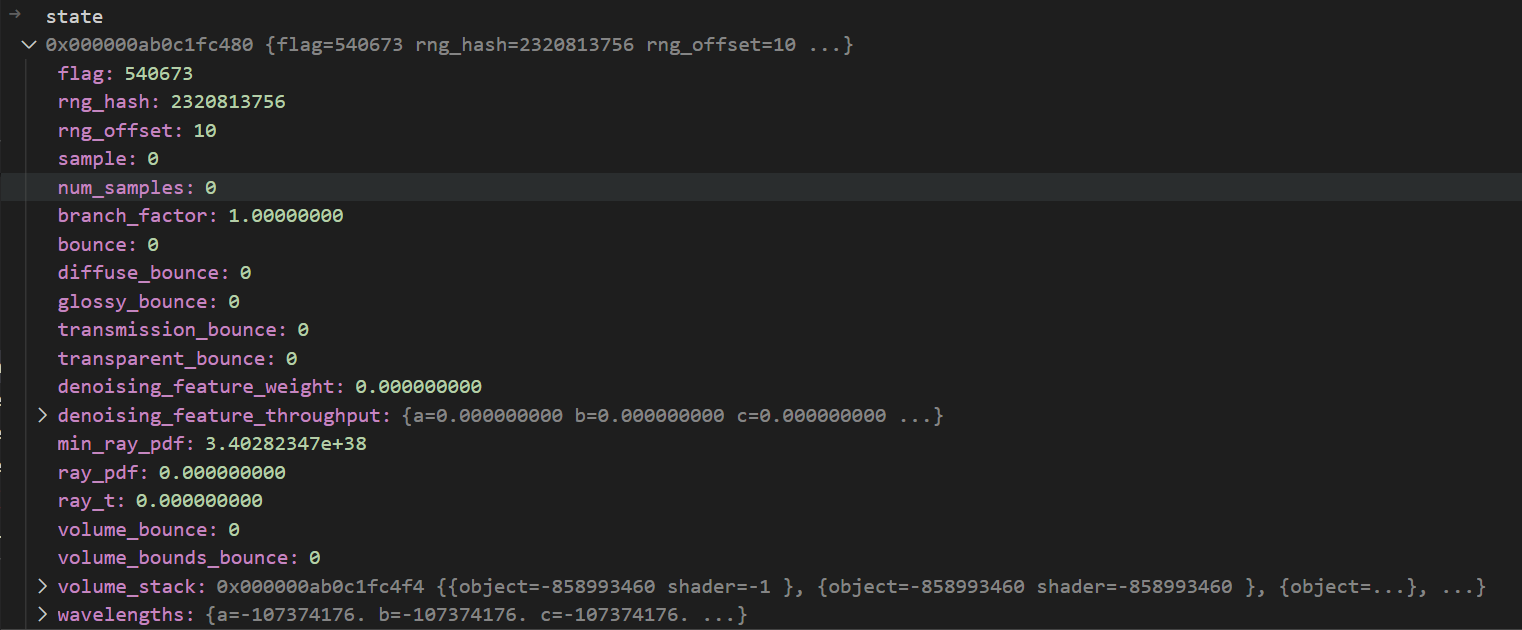
An issue has cropped up (separate to the importance sampling) where it seems like the wavelength seed only changes once every 10 samples. Is this something you’re familiar with? At first I thought it must be to do with the dimension we’re using, but it doesn’t seem to be the case; changing the dimension doesn’t seem to have an impact. Other things (film and lens position, time, BSDF u and v etc) seem to be correctly updating every sample.
What other variables are responsible for determining the result of path_state_rng_1D which might be constant for 10 samples at a time?
any preliminary results in terms of speedup or noise quality change?
I’d guess it’s particularly relevant for narrow spectra? Like, probably a good test would be to use different widths of the new gaussian spectral node
I don’t think there is anything that changes every 10 samples. Maybe it’s using the RNG before it has been initialized or something? Maybe the dimension number is invalid somehow, and the Sobol sequence has not been initialized for that dimension? Does it work when you use e.g. the time dimension instead as a test? Does it work with CMJ or PMJ sampler?
@pembem tested this, it only occurs with the Sobol sequence. It’s possible something hasn’t yet been initialised, I guess. I’m not sure what would have changed but that’s a good place to start looking.
I’ve tried using the same dimension as others such as time, but that didn’t seem to impact the results.
Once the core feature is there, I think it’ll make sense to either give the user presets or expose (yet another) spectrum curve in the UI which represents the wavelength sampling importance. That way a user could specify which wavelengths they deem ‘important’ for a render. For now, the main benefit is extending the sampling range to the wider 360-830 without a performance cost. Once I have the sampling working again properly I’ll do a comparison.
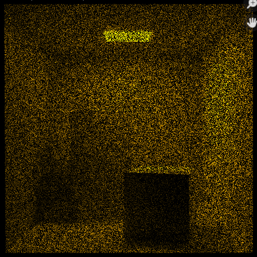
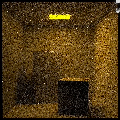
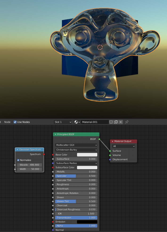
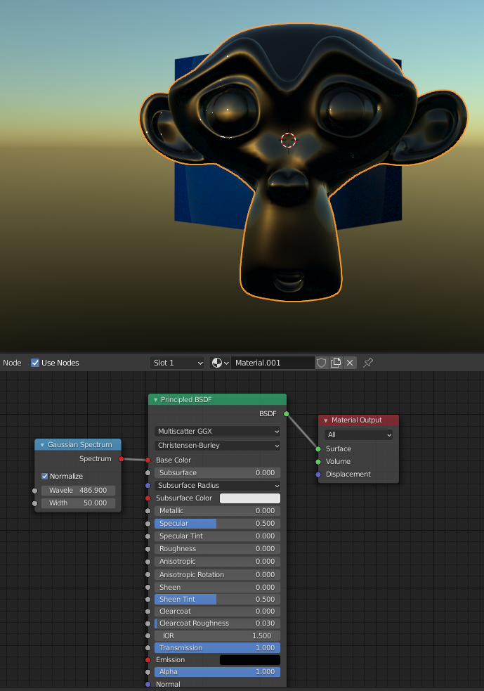
The issue only occurs when using Sobol sampling pattern. CMJ and PMJ work perfectly, here’s comparison of the scene rendered with identical settings except for sampling pattern:
I didn’t at all think of actual user input. Fiddling with something like that seems like a very niche-feature.
So basically what it’s gonna do is make more visible wavelengths (in that the response across the three receptors is stronger/brighter) more prominently sampled, more quickly reducing noise involving those wavelengths (and consequently, since they inherently have more effect on the overall image, also reducing noise overall) right?
How are you deciding what colors to sample more? Simply by the sum of responses? Or perhaps by the green response (which tends to be used as proxy for perceptual brightness if I understand right)?
That stuff is super technical and I don’t have any input at all on best practices or what not, just to be clear. I’m simply curious
Gotta remember, this kind of node is gonna produce a fairly narrow spectrum, filtering out a LOT of colors almost entirely. It will potentially look near opaque very quickly, especially at low widths. Materials rarely are like this though. While it’s fine to use this node for them, it’s probably best used for lighting. (Especially at very narrow width. Think lasers)
Additionally, you’re using this spectrum as a surface. It’s like a glass Suzanne coated with a very thin layer of very dark but clear color. You might want to try using it as volume absorption material instead. It’s also gonna be more realistic (if you’re going for actual thick glass, rather than something coated) as, say, the ears are gonna look somewhat lighter than the bulk of the head.
Also, I noticed that bounce depth matters quite a lot: You’ll probably want to up transmissive and specular bounces. It often makes for MUCH brighter materials.
I know it’s not at all optimal, but I tend to just max out bounces to make sure I don’t get any blackness where there shouldn’t be any.
Btw, on that note about normalization, @pembem22 what exactly does that mean? Does it normalize to a maximum of 1 or such that the area beneath is 1 or…? And will non-normalized tend to peak higher or lower?
'cause if non-normalized peaks above normalized, isolin’s result is unphysical (stuff actually grows brighter on transmission)
Yes you’re right. The current ‘importance’ of each wavelength is the XYZ sum of the wavelength’s coordinate. The idea is that this would be automated in the future using some scene heuristic (total light emitted could be a simple and relatively accurate one), but providing UI for now allow users use scenes with monochromatic light and resolve much, much faster for now.
The normalisation toggle switches between maintaining equal radiometric energy and being a lobe with a maximum of 1. Intended for using it with lights and materials respectively.
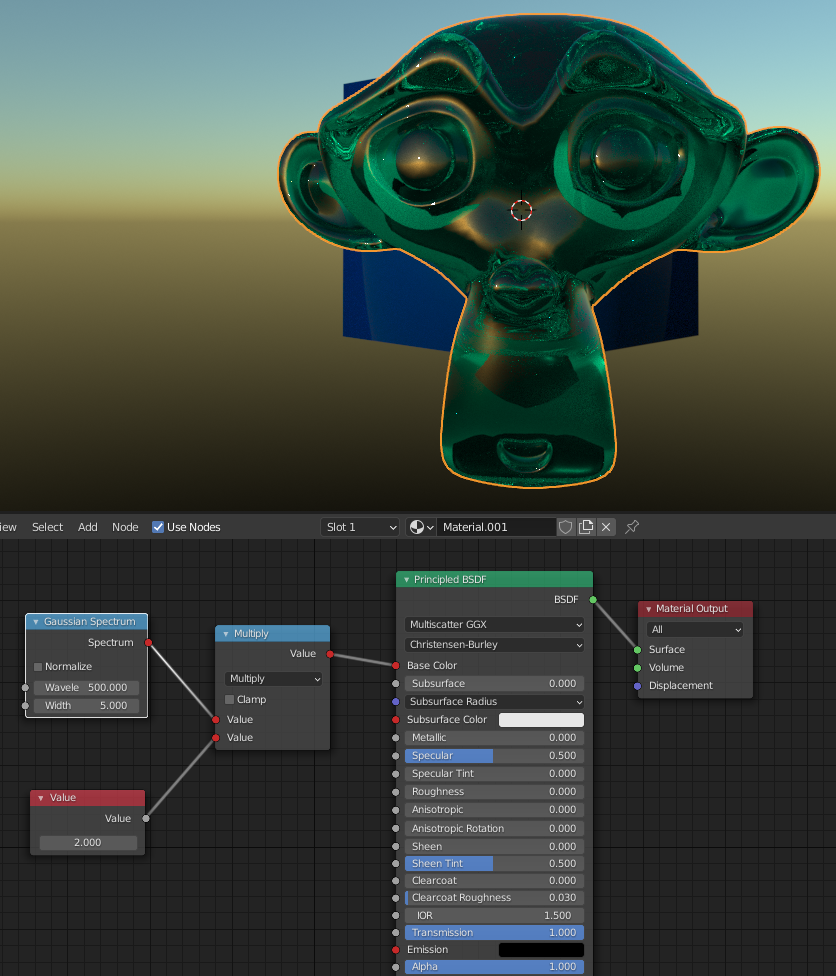
Multiplying the Gaussian spectrum by 2 is going to break energy conservation, raising it to a power and using a wider width instead would get a similar result while maintaining the energy conservation
Multiplying the Gaussian spectrum by 2 is going to break energy conservation, raising it to a power and using a wider width instead would get a similar result while maintaining the energy conservation
To add what smilebags said, you’ll want to raise it specifically to a low power (between 0 and 1) to make it effectively wider. - Changing the width parameter to something larger will have a similar but not identical effect.
Raising to a high power (above 1) will make the spectrum even sharper, thus making light less likely to pass through. It’s gonna be a bit like making the width smaller.
Raising to a negative power, meanwhile, will lead to energy non-conservation again.
Yep that would be possible. Not quite possible yet in this branch, but in theory that would be possible once we add the camera virtual primaries. Right now the curves don’t quite represent the spectral response of each ‘channel’ but instead represent the mapping from each wavelength directly to XYZ. We’d need a slightly more generic system to be able to handle that.
Technically there’s a lot of extras to consider. For instance, Mantis Shrimp are known for having a TON of different color receptors. But it turns out they use them in a different way from us. The color information from all those receptors aren’t nearly as finely processed as it happens for us. They are surprisingly bad at differentiating colors from what I read.
But what’s certainly theoretically possible is to obtain an image per color channel at least. It’s just not actually what they’d see.
In a similar way you could get what amounts to human night vision images by using the fourth kind of receptor we have as a basis.
It’s still pretty cool, though! I love the direction and amazing progress you guys make! Once it becomes per-channel mapping it will open up a world of possibilities for both scientific visualization and look dev for retro and modern “film-look”. Fingers crossed!


 Once it becomes per-channel mapping it will open up a world of possibilities for both scientific visualization and look dev for retro and modern “film-look”. Fingers crossed!