Scaramuzza's omnidirectional model

Hi all,

I am using Blender to generate 3D images for my PhD. I would like to output visual images and optical flow.
Thanks to Blender, I can get the Vector pass which works like charm on default cameras.
However, I would like to implement my own camera model to fit better a real camera I used for my experiments.
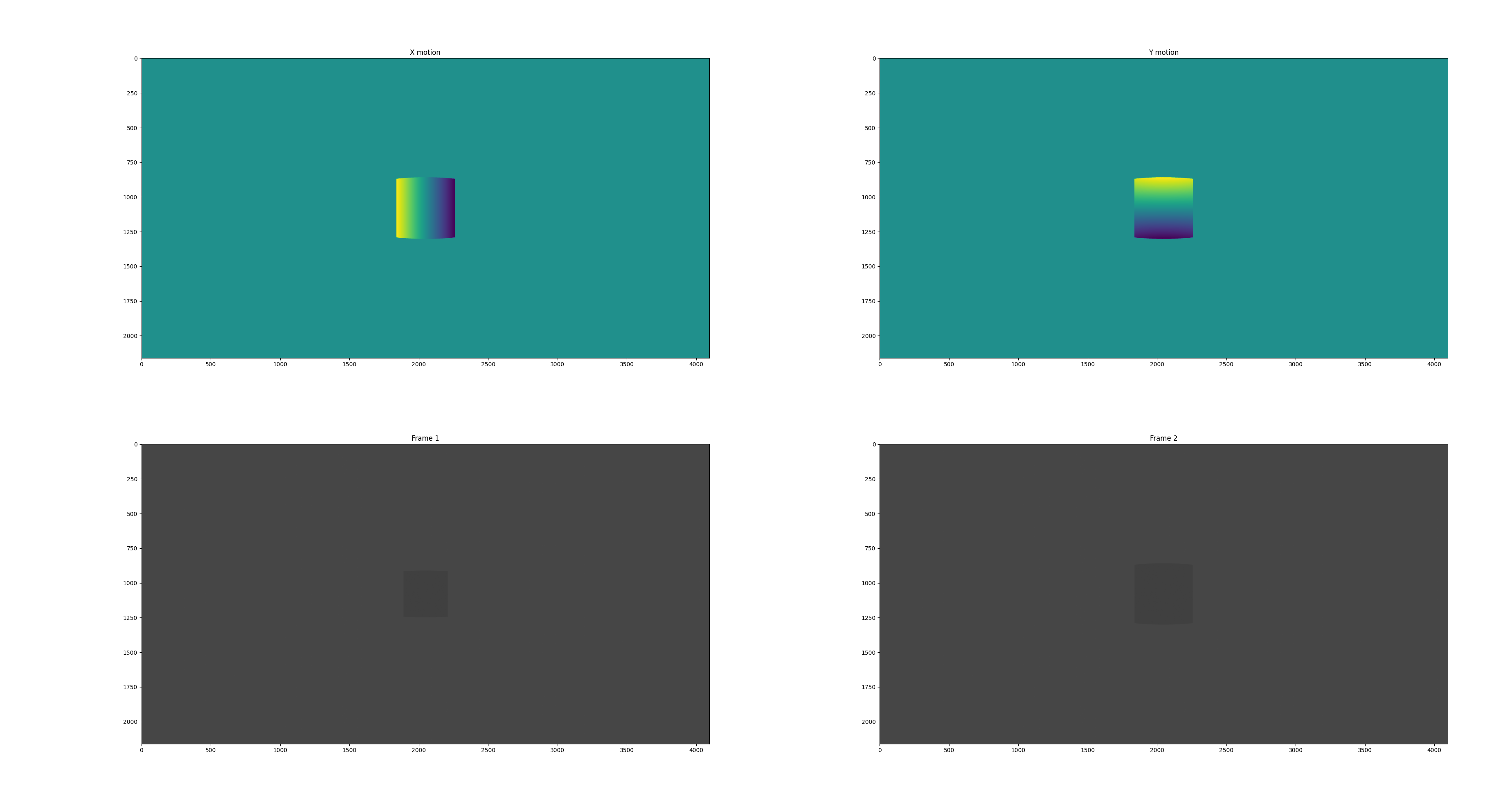
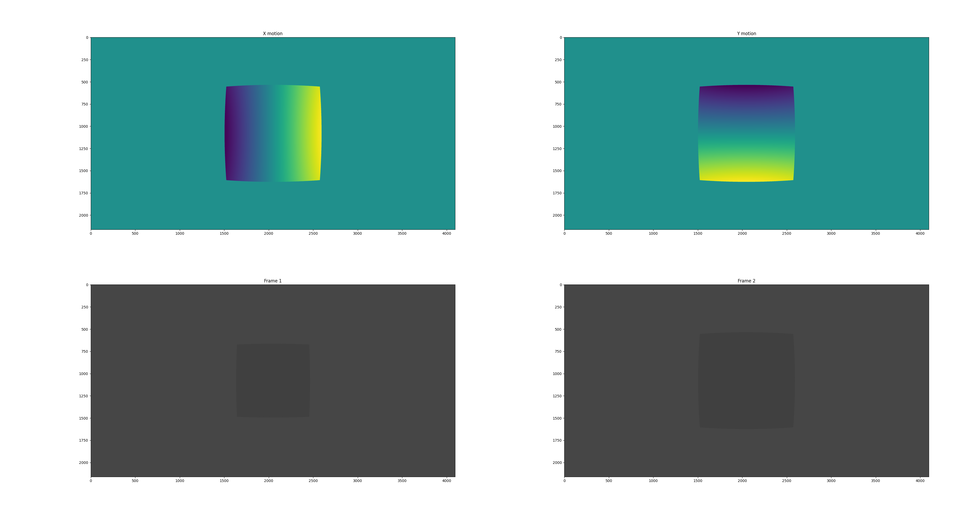
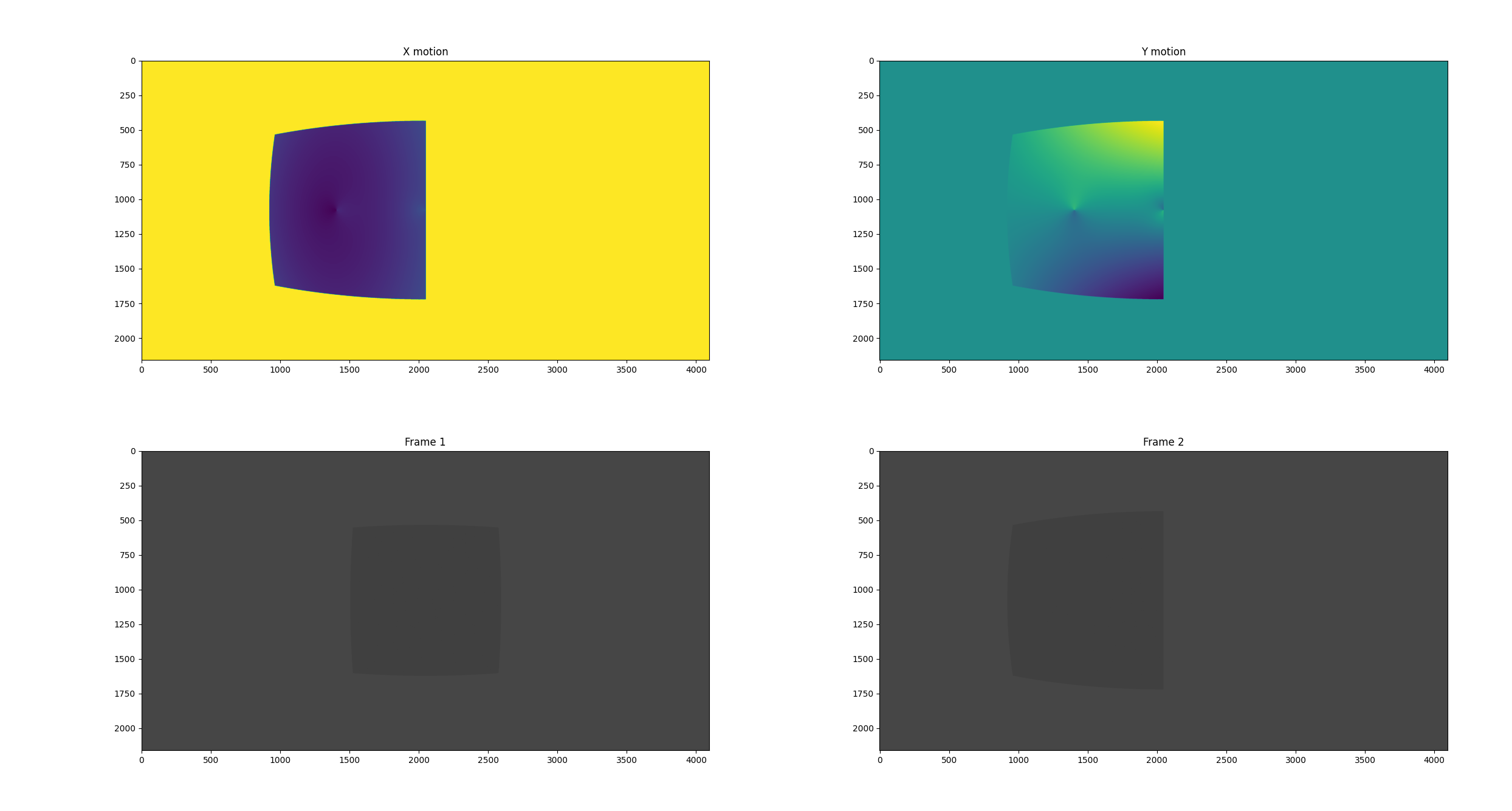
I was able to implement the visual model on Cycles (thanks to a few modifications on the following repository : rpg_blender_omni_camera/0001-Add-omnidirectional-camera-model-to-Cycles-rendering.patch at master · uzh-rpg/rpg_blender_omni_camera · GitHub). It works like charm. However, the optical flow one seems to have a scale issue.

I use the equations from : Fisheye Calibration Basics - MATLAB & Simulink - MathWorks France

The function omni_to_direction works perfectly. The function I am having troubles with is “direction_to_omni”.

ccl_device float3 omni_to_direction(float u,
float v,
float imageWidth,
float imageHeight,
float radiusPixels,
float a0,
float a1,
float a2,
float a3,
float a4,
float kC,
float kD,
float kE,
float cx,
float cy,
float invDetAffine) {
// scale coordinates and shift center
u = u * imageWidth - cx;
v = imageHeight * (1.f - v) - cy;

if(radiusPixels > 0.f && uu + vv > radiusPixels*radiusPixels)
return make_float3(0.f, 0.f, 0.f);

// inverse affine transformation
const float affine_u = invDetAffine * (kC * u - kE * v);
const float affine_v = invDetAffine * (-kD * u + v);

// ray z-direction
const float rho2 = affine_u * affine_u + affine_v * affine_v;
const float rho = sqrtf(rho2);
const float z = a0 + a1rho + a2rho2 + a3rho2rho + a4rho2rho2;
const float invnorm = 1.f / sqrtf(affine_uaffine_u + affine_vaffine_v + z*z);

return make_float3(
invnorm * z, // Turns out we need to remove the minus sign here to look in the right direction
- invnorm * affine_u,
- invnorm * affine_v
);
}

ccl_device float2 direction_to_omni(float3 dir,
float imageWidth,
float imageHeight,
float kC,
float kD,
float kE,
float cx,
float cy)
{
const float y = dir.y;
const float z = dir.z;

const float affine_u = kC * y + kD * z;
const float affine_v = kE * y + z;

const float u = 0.5f * affine_u + (cx / imageWidth);
const float v = 0.5f * affine_v + (cy / imageHeight);

return make_float2(u, v);
}

All the process happens in kernel_projection.h.

Do you have any idea where my implementation fails ?

1 Like

What do you mean by a scale problem? It will be easier if you share an image showing the problem.

Also your patch could benefit from a clean up. Run make format in Blender root folder to make sure you are not changing more things than needed (you can also setup your IDE to do that automatically)

1 Like

direction_to_omni should be the inverse of omni_to_direction. It seems unlikely that can be the case when it doesn’t take into account the a0-a4 and invDetAffine parameters?

2 Likes

Let’s illustrate it with an example. First, let’s have a look at what happens when an equirectangular camera is facing a cube and moving forward:

On this image, we have the two images captured at the bottom and the X and Y motions of the pixels at the top.
If we look at the (maltplotlib) coordinates of the top-left corner of the cube, one can identify this corner to move from the coordinates X : 1890 Y : 918 to the point X : 1837, Y : 868.

The X and Y motion values confirm this motion.

When I use my camera model on the same scene, the X and Y motion show the correct direction of the cube’s corner, but the values do not match the expected ones.

I tried for several camera trajectories and I cannot find where the problem comes from.

This is what it looks like with my own camera model:

1 Like

Thank you for your reply.
My understanding is that a0-a4 are required in the first function to compute Z which is required for normalizing the output vector. Because the input of the second function is already normalized, it doesn’t seem necessary to use them.

Regarding the invDetAffine. It is used to compute the inverse of the stretch Matrix defined here : https://fr.mathworks.com/help/vision/ug/fisheye-calibration-basics.html This inverse is required to compute the hypothetical image plane.

Maybe I misunderstood a part of the equations ?

1 Like

The parameters a0-a4 change the Z component and so the magnitude of the vector before normalization. And when normalizing, the X/Y get divided by the magnitude.

Logically, if parameters are required for the forward function they should also be required for the inverse function. Otherwise they are not required, or the function is not invertible.

1 Like

It definitely makes sense.
Would something like this be better ?

ccl_device float2 direction_to_omni(float3 dir,
                                float imageWidth,
                                float imageHeight,
                                float a0,
                                float a1,
                                float a2,
                                float a3,
                                float a4,
                                float kC,
                                float kD,
                                float kE,
                                float cx,
                                float cy)

{

float affine_u = dir.y;
float affine_v = dir.z;

const float rho2 = affine_u * affine_u + affine_v * affine_v;
const float rho = sqrtf(rho2);
const float z = a0 + a1 * rho + a2 * rho2 + a3 * rho2 * rho + a4 * rho2 * rho2;
const float norm = sqrtf(affine_u * affine_u + affine_v * affine_v + z * z);

affine_u *= norm;
affine_v *= norm;

const float u_stretched = kC * affine_u + kD * affine_v;
const float v_stretched = kE * affine_u + affine_v;

const float u_shifted = u_stretched + (cx / imageWidth);
const float v_shifted = v_stretched + (cy / imageHeight);

return make_float2(u_shifted, v_shifted);
}

I don’t think that’s correct either. You can’t ignore the invnorm factor for computing affine_u and affine_v.

There are existing implementation of the inverse function that you could look at:

1 Like

Many thanks for the suggestion @brecht.

I found that that the code you suggested uses the inverse polynomial coefficients which were pre-computed. Using the OCamCalib Matlab toolbox I was able to compute them as well.

This is my implementation (Ci are the inverse coefficients):

ccl_device float2 direction_to_omni(float3 dir,
                                    float imageWidth,
                                    float imageHeight,
                                    float a0,
                                    float a1,
                                    float a2,
                                    float a3,
                                    float a4,
                                    float kC,
                                    float kD,
                                    float kE,
                                    float cx,
                                    float cy)
{
  // Make sure the norm won't be zero.
  float affine_u, affine_v;
  if (dir.y != 0.0f && dir.z != 0.0f)
  {
      affine_u = dir.y;  
      affine_v = dir.z;
  }
  else
  {
    affine_u = 10e-9f;  
    affine_v = 10e-9f;
  }


    const float norm = sqrtf(affine_u * affine_u + affine_v * affine_v);

    const float theta = atan(dir.x/norm);
 
    const float theta2 = theta * theta;
  const float c0 = 2.4535f*10e3f;
  const float c1 = 1.2974f*10e3f;
  const float c2 = -0.0350f*10e3f;
  const float c3 = 0.2371f*10e3f;
  const float c4 = 0.0751f*10e3f;
  const float c5 = 0.0192f*10e3f;
  const float c6 = 0.0463f*10e3f;
  const float c7 = -0.0082f*10e3f;
  const float c8 = 0.0068f *10e3f;
  const float c9 = 0.0345f*10e3f;

  const float rho = c0 + c1 * theta + c2 * theta2 * c3 * theta * theta2 + c4 * theta2 * theta2 + c5 * theta * theta2 * theta2 + c6 * theta2 * theta2 * theta2 + c7 * theta * theta2 * theta2 * theta2 + c8 * theta2 * theta2 * theta2 * theta2 + c9 * theta*theta2*theta2*theta2*theta2;

  affine_u /= norm;
  affine_u *= rho;

  affine_v /= norm;
  affine_v *= rho;


  const float u_stretched = kC * affine_u + kD * affine_v;
  const float v_stretched = kE * affine_u + affine_v;

  const float u_shifted = (u_stretched + cx )/ imageWidth;
  const float v_shifted = (v_stretched + cy )/ imageHeight;

  return make_float2(u_shifted, v_shifted);
}

I know the implementation is not optimized but I wanted to check if it worked first.
Unfortunately it does not work. The vector pass values are several magnitude order too high.

It looks like my rho factor is too big compared to the norm I compute at the beginning.
Any idea why I face such a difference between the two values ? Have I forgotten to divide the “rho” value by another one ?

I finally managed to obtain the correct results. The inverse coefficients I was using were not correct.

You can find below the final code. Note that this code is working for my specific camera and is very slow. I will make sure to create an optimized and generic code later.

ccl_device float2 direction_to_omni(float3 dir,
                                    float imageWidth,
                                    float imageHeight,
                                    float a0,
                                    float a1,
                                    float a2,
                                    float a3,
                                    float a4,
                                    float kC,
                                    float kD,
                                    float kE,
                                    float cx,
                                    float cy)
{
  // Make sure the norm won't be zero.
  float affine_u, affine_v;
  if (dir.y != 0.0f && dir.z != 0.0f)
  {
      affine_u = dir.y;  
      affine_v = dir.z;
  }
  else
  {
    affine_u = 10e-9f;  
    affine_v = 10e-9f;
  }


    const float norm = sqrtf(affine_u * affine_u + affine_v * affine_v);

    const float theta = atan(dir.x/norm);

    float theta_temp = 1.f;
    
  std::string coeffcientsStr = "-4.36183606615469,7.94608489711144,7.81262460377262,-12.0979631737921,-17.8118671828294,16.6524622138909,-9.24646140552358,35.7528267744949,-20.4243132315004,89.7547601335267,-227.285830968754,3.73585088199427,-1355.81324306746,2447.79511759095";
  std::vector<std::string> coefficientsStrSplitted;
  split( coeffcientsStr, coefficientsStrSplitted, ',' );
  std::reverse(coefficientsStrSplitted.begin(), coefficientsStrSplitted.end());
   
  float rho = std::stof(coefficientsStrSplitted[0]);
  for(int i =1; i<coefficientsStrSplitted.size(); i++)
  {
    theta_temp *= theta;
    rho += theta_temp * std::stof(coefficientsStrSplitted[i]);
  }


  affine_u /= norm;
  affine_u *= rho;

  affine_v /= norm;
  affine_v *= rho;


  const float u_stretched = kC * affine_u + kD * affine_v;
  const float v_stretched = kE * affine_u + affine_v;

  const float u_shifted = (u_stretched + cx )/ imageWidth;
  const float v_shifted = (v_stretched + cy )/ imageHeight;// -1.0f;

  return make_float2(u_shifted, v_shifted);
}

While the vector pass values are now correct for most of the points (I always check the displacement of my cube’s corners), I do have some strange behavior for the middle of my cube. Do you think it can come from an issue withe the center coordinates or the epsilon value I add when my norm is null ?

The following picture illustrates the problem.