Replacement-based Procedural Modelling [Proposal]

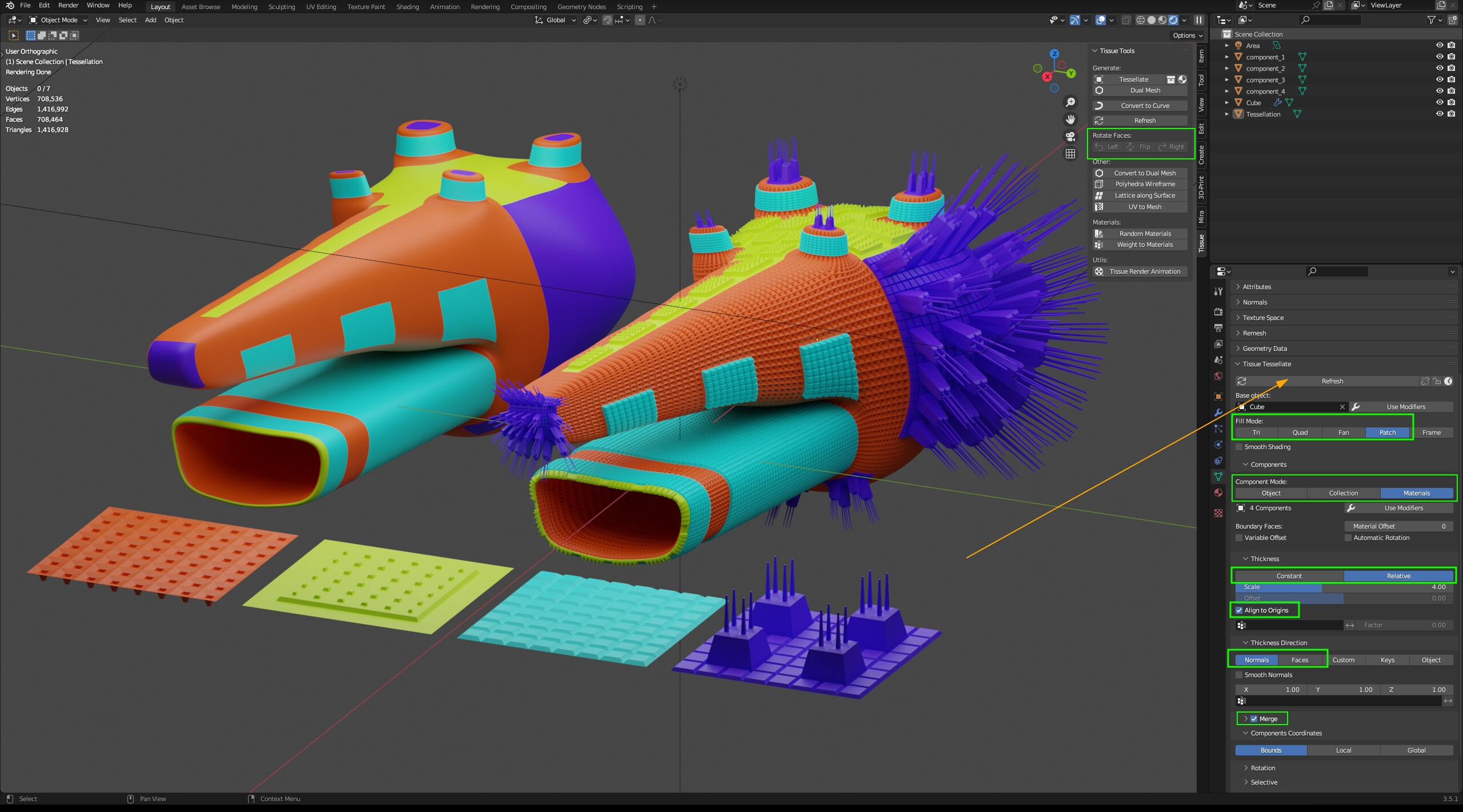
This document proposes a new workflow for procedural modelling which makes extensive use of a new Replace Faces node. The proposal still has some open ends that have to be solved going forward.

The general idea is that many objects can be modelled by starting with a primitive shape and then repeatedly replacing individual faces with new geometry that is embedded into the mesh.

This is quite different from traditional modelling where one rarely thinks about operations as replacing some geometry with new geometry. The problem with traditional modelling operators in a procedural context is that they usually have complex inputs that are hard to generate procedurally. For example, specifying where exactly an edge loop should be inserted on a mesh is easy in the 3d view by just hovering over a specific edge. Procedurally generating that input is hard. It’s even harder for e.g. the knife operator.

Repeatedly replacing parts of a mesh more naturally fits into geometry node. It also makes it possible to build independent details of a mesh separately and to stitch them together afterwards.

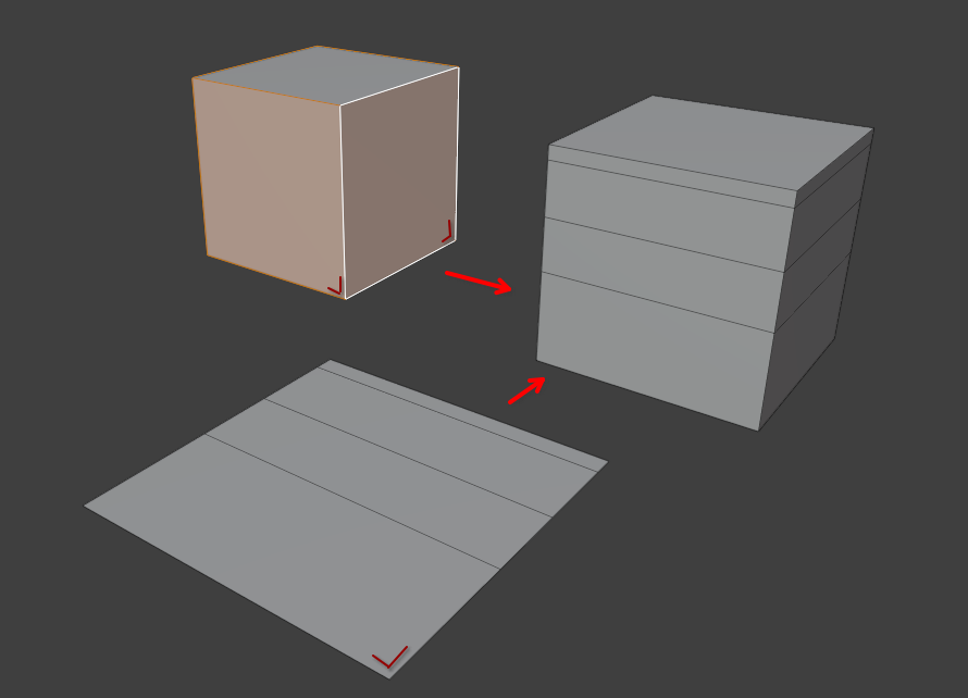
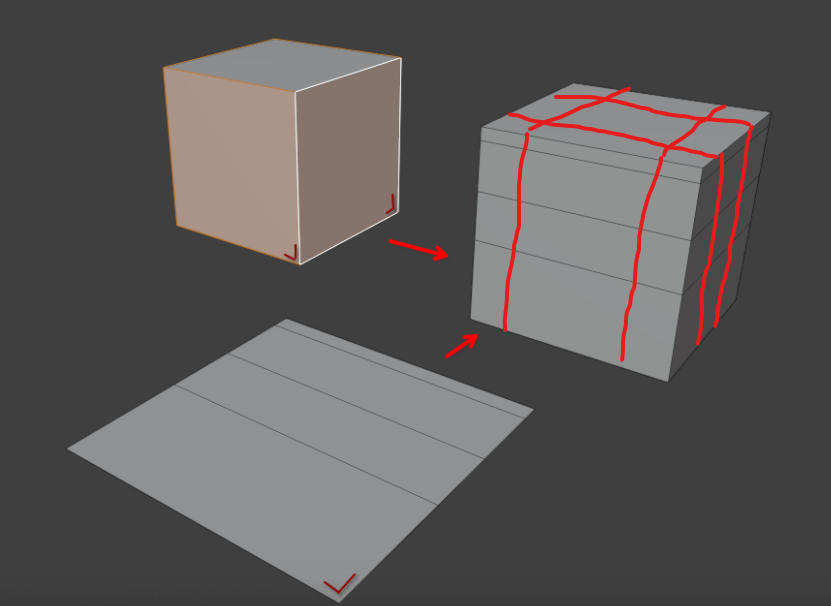
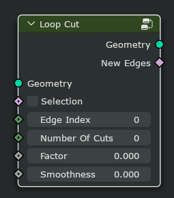
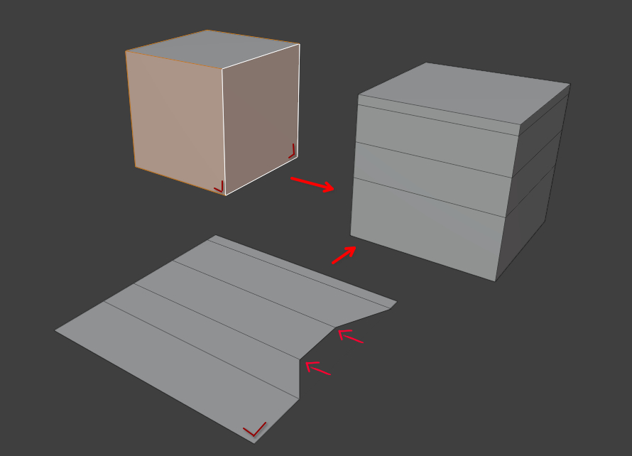
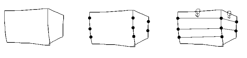
A reason for why a replacement-based workflow fits better into geometry may be that it better separates the “what” from the “where”. For example, in the image above, one first builds the loop cut on a single plane and then inserts it on all selected faces. In traditional modelling, one would build the loop cuts directly on the target mesh. The separation makes it easier to think about both things independently.

Replace Faces

At the core of this workflow is a Replace Faces node. A couple additional nodes may be needed under some circumstances as well (e.g. Dissolve Edges).

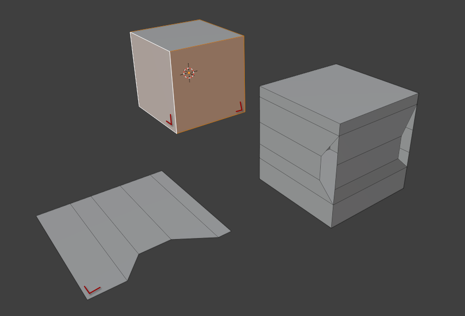
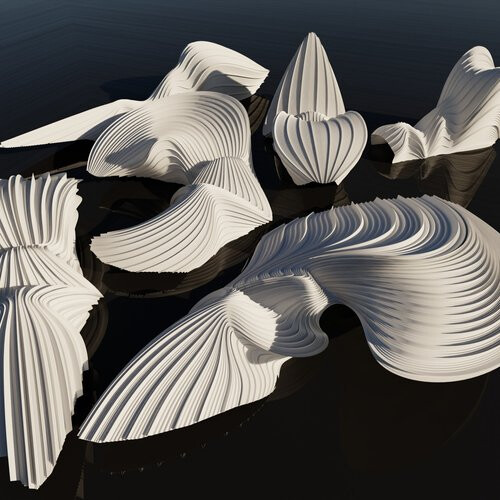
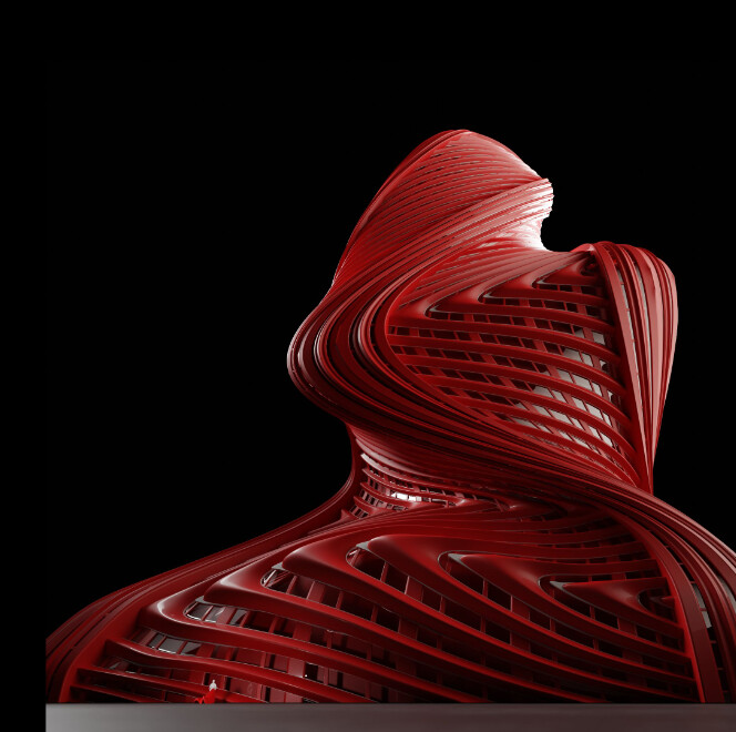
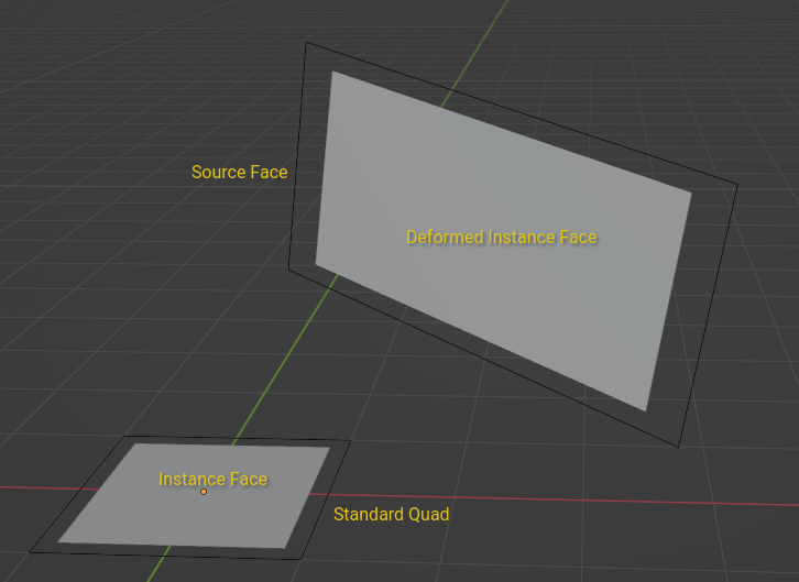
The Replace Faces node removes selected faces and inserts other geometry at the same place. If the inserted geometry is a mesh, it can optionally be linked with the rest of the mesh. For example, the resulting mesh in the image above is a single manifold mesh island. The replacement geometry can also be point clouds and curves though.

The inserted geometry is deformed to the face. This deformation is not always well defined, especially for ngons because there are many possibilities. Maybe multiple deformation methods are needed for more complex cases, or we need the ability to customize this somehow.

image.png

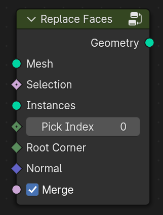
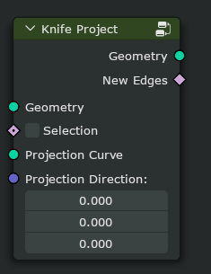
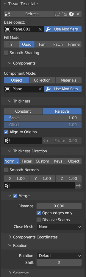
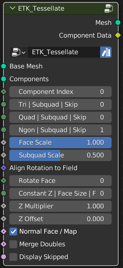
This image shows an initial design for the new node. It’s likely that it has to be modified a bit as we learn more about different use cases. The general idea is that for every selected face, one instance is picked from the Instances input which is then inserted.

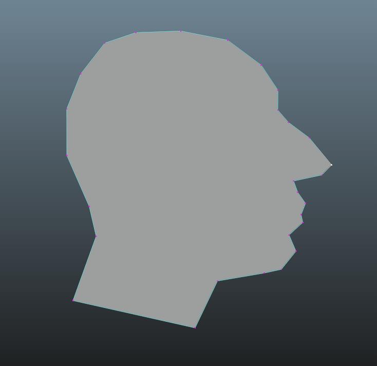
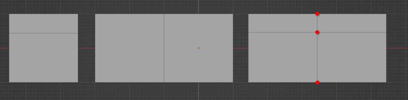
The Root Corner determines an “anchor” in each face. It determines the orientation of the inserted geometry. The image above shows the root corner on the selected faces.

Deformation

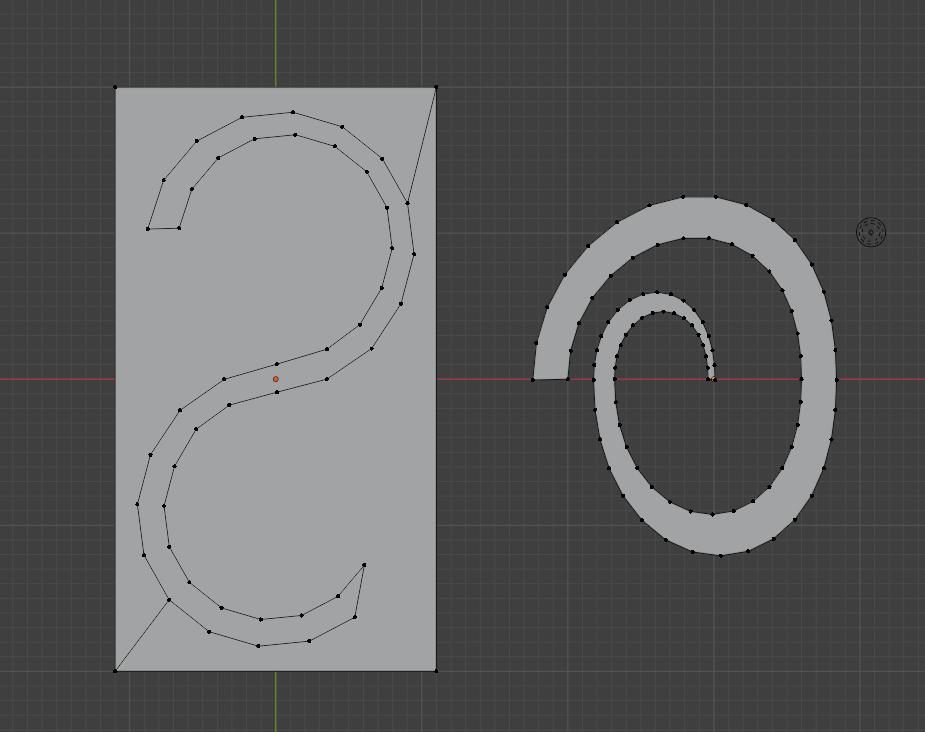
The instances passed into the node are expected to be normalized. There are different ways this normalized space can be defined. One possibility is to define a standard triangle, quad and ngon with arbitrary vertex amount as the output of the Mesh Circle node.

If the replacement for a face is exactly the corresponding standard ngon (with the same number of vertices), the mesh is not changed at all. If the replacement is something else, the output geometry changes.

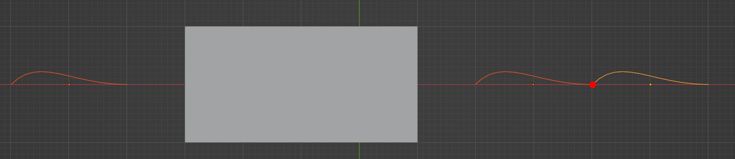
Points that are not exactly on the XY-plane will be moved on the direction of the face (corner) normal.

Merging

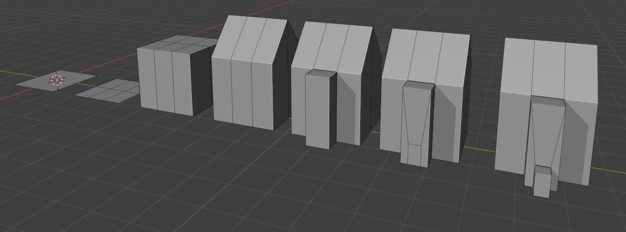
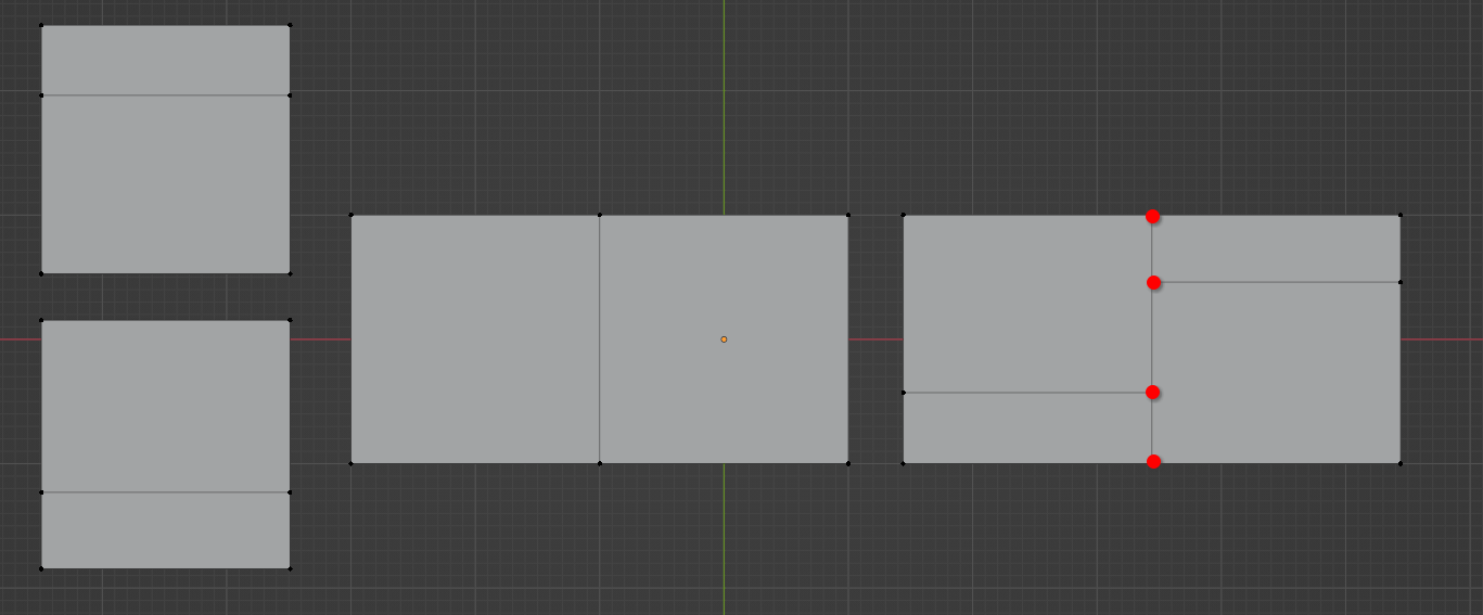
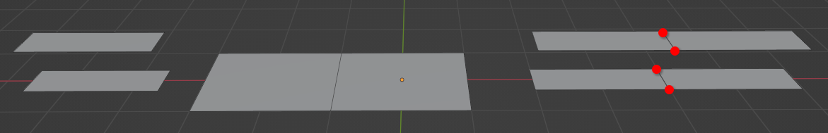
The most difficult aspect of this node to get right is merging. The general idea is that all points that are exactly on an edge of the standard ngon or above/below that may be merged with points on neighboring replacement geometry if the points are close. Points lying on the edge may also be merged with faces that are not replaced.

Some examples of different situations:

Further Thoughts

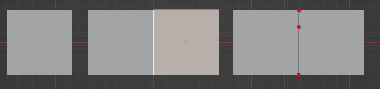
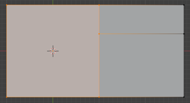
  • Sometimes it may be useful to skip certain corners when deciding which standard ngon to use. In the example below, the face on the left could be treated as quad under some circumstances.
    image.png
  • Sometimes there may be some points that can be merged by the node but should not.
  • Often it may be useful to remove edges and faces that are created between two replacement geometries. For example, replacing every face in a quad mesh with a cube could then behave as a solidify node.
  • It’s not entirely clear whether materials should be propagated from the face or the replacement geometry. Both seem reasonable depending on the goal.
  • A node to dissolve geometry (similar to e.g. the Dissolve Edges operator) could be combined with the Replace Faces node in powerful ways. Together they can be used to replace patches of faces on a mesh with new topology.
  • There are different ways to propagate attributes from the face to the replacement geometry. For example, when the replacement geometry contains curves, the attributes should be propagated from the face to the points or curves domain.
32 Likes

This would be great to have alongside regular commonly known modeling operations but I hope this won’t come at the expense of having those regular modeling operators in Geometry Nodes. Main issue I see with this workflow is that it’s quite difficult to build intuition for this from a point of view of someone used to common modeling workflows (extruding, beveling, insetting, loop cutting, subdividing, etc…)

Taking this image for example:


It isn’t obvious to me what it would take to do a simple shape like this. But taking a guess I would have to:

  1. Build two types of the faces, the side face and the top face.
  2. Make sure the edges of the top face perfectly align with the edges of the side face.
  3. Perform one face replacement for selection of side faces.
  4. Perform another face replacement from the top and bottom faces.

With current limited toolset, I don’t know how would I even build the side face procedurally. I mean I would probably create 1x4 grid and them somehow filter out the edges I want to offset off center by selecting edges the direction of which aligns with certain axis but also they have more than one face neighbors. It’s certainly doable, but quite a lot of steps.

This is what confuses me the most. Imagine having “Loop Cut” geometry node. This node would have just a few inputs:

  1. Edge index - non-field integer
  2. Number of cuts - integer
  3. Factor - float
  4. Smoothness - float
  5. Selection - bool field
    image
    (I didn’t figure out how to turn the integer socket from field to single value)

To recreate the same result above. I could simply get a location, using for example location of Empty object. I could then sample edge nearest to that location and I could use it’s index as the “hovering edge selection” equivalent of the loop cut operator. I could then set number of cuts to 3 for the side face of the image above, and offset them off-center using the factor value as shown on the image above.

I could then create another Loop Cut node, grab one of the horizontal edges instead of vertical ones, make another loop cut, and if the node outputted newly created edges as bool field, and we finally had bevel node, I could just bevel that one edge loop to create two loops spaced apart.

Now, for the knife operator example:
The procedural node version of the knife tool should be more like the knife project operator blender has. It should simply take input geometry, curve geometry, a vector to define direction of the projection, and selection mask. The supplied curve would then simply be projected onto input geometry in the direction of the supplied vector and optionally only affect the selection-masked faces.
image

So in a nutshell:

  1. This proposed functionality would be very useful
  2. BUT, it should not close doors to implementing the usual modeling operators most people are used to.
  3. I think most common modeling operators are actually quite geometry-nodes friendly, it just takes a little bit of out of the box thinking.
7 Likes

Interesting idea. This workflow is kind of similar to one of the functionalities from the Tissue Addon (Tessellate) where a component is instanced on base mesh according to various parameters.
In your proposal the instanced face is laying flat on XY plane - same as this works in Tissue.

Here is one of my assets made with this addon:


Regarding deformation I think it would be good to plan ahead for more complicated workflows. I don’t know how you plan to deform the instances if they aren’t flat in Z axis. Tissue can do this and it might be helpful to check how. Tissue also can deform instances on a mesh that has different subdivision.

I prepared small scene with basic Tissue setup. In the screenshot I marked with green most important modes for face deformation. After making change hit refresh (marked with orange). tissue_tesselate.blend.txt (7.3 MB)

In the N panel there are options for face rotation, but you need to switch to Cube object and enter edit mode (also all components are symmetrical, so nothing will change). I assume this could be replicated with rotating Root Corner index?

Lastly I agree with Ludvik about the importance of having low-level nodes for mesh edit. Or default nodegroup asset at least. Both Loop Cut and Knife project would be great to have. Same as Edge Rings.

7 Likes

I think you’re making an interesting point about how more familiar nodes are helpful. But I think a single edge index input is a non-starter. Such a node should be able to influence an arbitrary number of face loops, not just one. That’s essential performance wise, where we want to push the user to “batch” geometry processing to do more at once, which is much more conducive to good performance. It’s also essential that people don’t have to use loops to influence more than a single element for UX.


Personally I like this proposal a lot, in the big picture. I just worry that it will be hard to implement the special/fast cases of merging in a way that will actually allow this to be a low level implementation of many other modeling operations.

5 Likes

True, I was just worried about two issues:
1, Since we currently don’t have any lists/arrays I had no idea how selecting only some edges to create edge loop from would work. In that case it’d have to probably be bool field evaluated on edges domain?
2. I was also thinking about case where order of the edge loop creation could affect what the resulting mesh is. Not sure if there was such case.

In any case though, I am sure you’d have much better idea at figuring out how to implement it. I don’t want to divert from the original proposal for replacement based modeling. I think it’s really promising. I just wasn’t sure about the argument that sounded like we should have replacement based procedural modeling because the mainstream modeling operators (like loop cut or knife tool) are too procedural workflow unfriendly. I think replacement based workflow should complement mainstream modeling techniques (extruding, beveling, insetting, loop cutting, subdividing…), not replace them.

The other mainstream DCCs that utilize procedural modeling heavily solve this issue by having a good interaction between 3D viewport and procedural modeling graph, such that users can interactively pick mesh elements in the viewport and quickly turn them into index based selections to work in the procedural graph with. I think focusing on solving that limitation first makes a lot more sense than trying to completely reinvent the established modeling paradigms, as that will come with its own set of substantial limitations.

3 Likes

This honestly doesn’t make a lot of sense to me, perhaps I’m too embedded in the old ways to see the benefit. You’re proposing a rather radically different way to model stuff, right? From what I understand it seems mostly aimed at modeling blocky shapes? or is that just bias from your examples?

What is the benefit of that exactly? how does it fit into a broader modeling workflow, and what kind of assets would be good candidates to apply onto? right now this seems a bit floaty

Note, I see you’re thinking of ways to merge the contributing geometries when the amount of vertices don’t match up. This is only really possible if the edges are exactly colinear, because ngons have to be planar to be usable/predictable, hence my remark on this being aimed at “blocky shapes”. For instance, what happens if some vertices are moved that way ?


Does the concept rely on using normalized flat planes? kind of like authoring VDM brushes?

Yes, if the goal is simply to facilitate procedural modeling, gizmos and general viewport interactivity would go 80% of the way there, I think.

2 Likes

This would be great to have alongside regular commonly known modeling operations but I hope this won’t come at the expense of having those regular modeling operators in Geometry Nodes. Main issue I see with this workflow is that it’s quite difficult to build intuition for this from a point of view of someone used to common modeling workflows (extruding, beveling, insetting, loop cutting, subdividing, etc…)

I’m not generally against having nodes or node groups for these things, but I am trying to cover many use cases in a good and efficient way with few built-in nodes. I think the output mesh of various common mesh modelling operations is somewhat tricky to continue to work with procedurally because you don’t have as direct control over what is actually changing and you can’t inject attributes on the new geometry.

It isn’t obvious to me what it would take to do a simple shape like this. But taking a guess I would have to:

Your steps seem about right. I think with this approach you have a lot of control over the result. Much more than if you would add loop cuts. I’m not sure how procedurally adding the loopcuts in your example should work.

Regarding your Loop Cut and Knife Project node I would mostly say the same that Hans said already. Performance when doing these small operations one by one is likely much worse compared to doing more changes at once. Also with both nodes you have less control over what is actually happening in the mesh and it’s harder to continue working with the mesh procedurally.

So I’m not against these nodes, and it seems quite likely that we will have them built-in or as node groups eventually, but they are quite specific and don’t open up as many possibilities as the proposed node imo.

In your proposal the instanced face is laying flat on XY plane - same as this works in Tissue.

The proposal is not limited to that. I even mentioned that the face (corner) normal would be used to deform points that are not on the XY plane. I think this would work very similar to what the Tissue addon does.

The other mainstream DCCs that utilize procedural modeling heavily solve this issue by having a good interaction between 3D viewport and procedural modeling graph, such that users can interactively pick mesh elements in the viewport and quickly turn them into index based selections to work in the procedural graph with.

I don’t consider hard coded index based selections (except for primitive shapes) procedural. Using those breaks the setup if any input parameter changes. We can support such workflows as well of course, but it doesn’t really have priority right now.

You’re proposing a rather radically different way to model stuff, right? From what I understand it seems mostly aimed at modeling blocky shapes? or is that just bias from your examples?

Nothing about the proposal is about blocky shapes, it’s just all I can do as a modeller ;D
One goal here is to allow users to insert any topology (manually or procedurally created) into the mesh to allow for abitrarily complex geometries.

For instance, what happens if some vertices are moved that way ?

That still works, it just doesn’t merge the vertices that are not on the edge.

5 Likes

Hi Jacques! I really like this idea, and I also that what you are trying to do seems very similar to the Tissue Addon, which essentially takes a component and maps it onto the local space of each face of the base mesh.

@Erindale (and also other people), have created node groups that replicate some of the tessellation properties of Tissue.

I use Tissue quite a lot, and would love to have tessellations work more natively and faster in Geometry Nodes. Thus far, I still resort to the Tissue addon, due to its more granular settings, and in particular rotation of the faces. Rotation is something I’ve struggled with to get correct geonodes-based tessellation for objects like these, which are all done with a simple base mesh and a component in Tissue:

image

And it gets even tricker for objects like these, where different faces get a different kind of component based on the face material in Tissue:

I had to go and manually rotate the faces in Tissue, which has options to either follow the UV layout to understand the rotation, and not sure how the other ones work (@AlessandroZomparelli ?)

It makes me wonder whether there is some kind of attribute that can be used for determining the rotation in geometry nodes :thinking:

In general, having easier way to create selections would be very welcome. Yet, going back to the context of the Tissue addon, material-base selections that get then processed to some kind of tessellations node can already solve this.

9 Likes

I’d like to imagine this staff in more complex picture.
Something like: Each face are projected on UV surface. Additional attribute might let to define UV surface position and normal.
So, instances with matched ID will be bisected by that uv shape in space.
And all next steps will be in that shape space.

  • Lookup for vertices for merging.
    • Optionally, found vertices, can be masked in certain context.That will let more control to select merged vertices or his groups.
  • Deformation.

Pretty sure such function can be done by node groups. UV Sample node would help here


I hope UV definition of base faces will solve this by the way.


I hope x2 Jagged Fields will let us do delete Island Index’like node at all and implement all such nodes (and Edge Rings as well) as node groups.

Summary


Pretty sure it’s okay to select Edges in Face Corner domain.
But in case if that will be required, Jagged Fields not planned for now, but eventually…

Summary

More info about this


Flip Normals node actually change that order.


Here is just one problem with something like Loop Cut node: That is too complicated. I mean, yeah, simple case with quads-only mesh and with same loops-value on each mirrored edge face.
But n-gon’s, triangles, custom patterns, … ? See Thoughts about topology editing.

We can support workflow like Resample Edges → Quad Fill:

But in general, topology-inserting workflow is the way to let user create it own topology in easy way.

More specific nodes can occur in the future, but now here is the best general solution.


This sounds like what geometry nodes are trying to prohibit. You shouldn’t do that. Please do not pick indexes from the viewport!


Old methods will not be removed. This is a way to solve higher level problems. Essentially, you create simple shapes as usual, but then you can not use instance only, but topologically merge them.


That is the way of creating the holes. Merging is not issues in you example. But yeah, mainly that target for merging task.

1 Like

I am not requesting some super smart advanced loop cut tool. I’d just like to see simple loop cut operator blender already has ported to GN, where instead of selecting the start edge the face loop is calculated from by finding the edge nearest to mouse cursor, I’d just specify edge(s) using their ID. I’d be completely fine if it didn’t create complete loops on non-quad geometry.

In theory that is true, index based selection is not procedural. But in practice, the most popular procedural modeling DCC out there supports that workflow and people have been using it on daily basis for more than a decade now. Practice has shown that once users are aware of the limitation that changes to underlying topology will invalidate index based selections, they will quickly learn to be careful about it, but still utilize it to their advantage.

The most effective modeling workflow will always be some proportion of manual and procedural mesh editing. Trying to do everything 100% procedurally just goes against the wind. For example in the other unnamed DCC, I can drop in curve primitive in the procedural graph, and edit it in the 3D view using curve pen tool to create basic curve shape to work with. It’s crazy to imagine setting up individual curve point locations and their tangents in some node based UI with no direct interaction in 3D viewport. It is doable, but gravely inefficient.

In Blender I can only use external curve object reference for this kind of workflow, but then what should be self contained as one object quickly becomes very messy set of dozen + scene objects switching between which is a pain.

But back to the topic. I like the proposal. I’d just back off on the mentions/idea that the reasoning for the proposal is that traditional modeling operations would not do the job as well. That’s the only disagreement I have.


TL;DR
If I actually had to model something, I can easily imagine myself being quickly roadblocked by the inflexibility of purely replacement-based workflow. In comparison, if GN had no replacement-based modeling tools at all, but was not lacking the most basic of modeling operators (inset, bevel, loop cut, per-face/edge subdivision, knife project), I would be able to achieve by order of magnitude more than I currently can with GN when it comes to mesh modeling.

I feel like the priorities are a bit upside down here. We are talking about establishing whole new modeling paradigms at a time when GN still doesn’t even have bevel node. To me it makes more sense to first completely finish the basic modeling operator/node feature set, and only after that’s done, re-evaluate if modeling possibilities of GN are still too limited.

3 Likes

I was implement loop cut node first half of this year and this modeling approach was proposed by me based on my thought about loop cut complexity (#108436 - WIP: resample topology node - blender - Blender Projects).
Simplicity is good. But this is a dead end for expansion. We can’t then simply add +1 input socket for each new mode that will collect 20 likes on the RCS, so you can do this by inserting your own mesh with needed topology in to faces in general.

But again, simpler and faster nodes can be extracted from the overall Topology Inserting later.


Until we will move whole blender data base into node tree, you should just create separate objects :sweat_smile:.


1 Like

If there were only triangle faces, it would be easier to gasp for me.

But quads could be concave, and n-gon could be something like this …

I’m puzzled … how to handle an arbitrary n-gon, which has a more complex shape?

Personally I like this proposal.
I already have some custom node groups which do something similar, so it fits quite neatly with my existing workflow.

1 Like

Is there a patch that we can test out with this?