I want to express my gratitude to the Cycles module team for their outstanding work on the shaders – bravo! However, I’ve noticed that the Cycles glass shader seems to be lacking in functionality. Unlike real-world glass properties, it often doesn’t allow light to pass through and requires workarounds to achieve desired results. I’m curious about the intended function of the Cycles glass shader and whether there are plans to address its limitations. I’m aware of the architectural glass toggle that @lukasstockner97 is working on, but the current glass node appears to be ineffective. Thank you!
1 Like
in what way is it ineffective? Could you explain?
The default glass shader simply won’t allow light through it. It’s easily evident. I don’t know what else to explain. https://youtube.com/clip/Ugkxw_iUAdO5XuHnDJ_ECAQx-7vN2NErgJ8V?si=z3ptMguZNS4JdXzl
I saw that this morning. Cycles does let light through glass, it’s just that Cycles is a heavy ray-tracer, and it doesn’t let as much through compared to other engines. Comparing it to LuxCore, which is developed to deal with such things is a bit of an unfair comparison. Arnold, another really commonly used raytracing engine has the same behavior as Cycles, and lets in less compared to other engines. It isn’t broken, it’s just the nature of the engine.
Architectural glass will do the hack in the video and pretty much eliminates that issue.
I acknowledge that it’s not broken, but the current behavior clearly falls short of the expected ideal, particularly in architectural visualization where there’s an expectation of light transmission through transparent mediums. No excuses should be made, given that this aligns with the inherent nature of glass objects.
We all quite aware of the workarounds and tricks but that isn’t ideal IMHO
2 Likes
@Roggii and @Bobo_The_Imp , I’m just going to clarify the what’s happening with the glass.
Lights are primarily sampled in Cycles (and many other ray tracing render engines) through a process called “Next Event Estimation” (NEE). The way this works is a ray will hit a surface (E.G. The ground), and make a decision on if it should do NEE or continue with random ray tracing, and if it decides to do NEE, it then picks a light and fires a ray straight at it. If there is a object in the way that’s not transparent, that ray is considered “in shadow” for that light.
The issue with glass is that it’s not 100% transparent, so it gets classed as an obstacle and marks the ray as “in shadow” (unless you are using the architectural glass trick).
So the fix is simple right? Just don’t mark rays that hit the glass during NEE as “in shadow”? Not really.
This can be done in two main ways.
- Make it so when a NEE ray hits a piece of glass, make the glass transparent. This is basically the same as the architectural glass trick.
- Just don’t mark the ray as “in shadow” and keep the glass glass. But then you encounter an issue. The distortion caused by the glass is likely to make it so the ray misses the light. So even with this technique, things aren’t going to be improved much.
So what can be done to improve it? A few things. Of which quite a few are already in Cycles.
Make glass rough:
When a ray encounters perfectly smooth glass, the ray passes through it in accordance to Snell’s law and is likely to miss the light. But if the ray encounters a rough piece of glass, the ray can decide to trigger NEE off of that piece of glass ensuring it hits a light. This can greatly help with the transmission of light through the glass.

Obviously increasing the roughness of the glass isn’t great for most scenes. For example windows, which are expected to be smooth.
So Cycles has a feature called “Filter Glossy”. Which will increase the roughness of the glass when a ray hits it after previously hitting a diffuse surface. This allows the glass to remain smooth to the camera and certain material types, but appear rough when it’s needed the most. It works similarly (but not the same) as this setup:
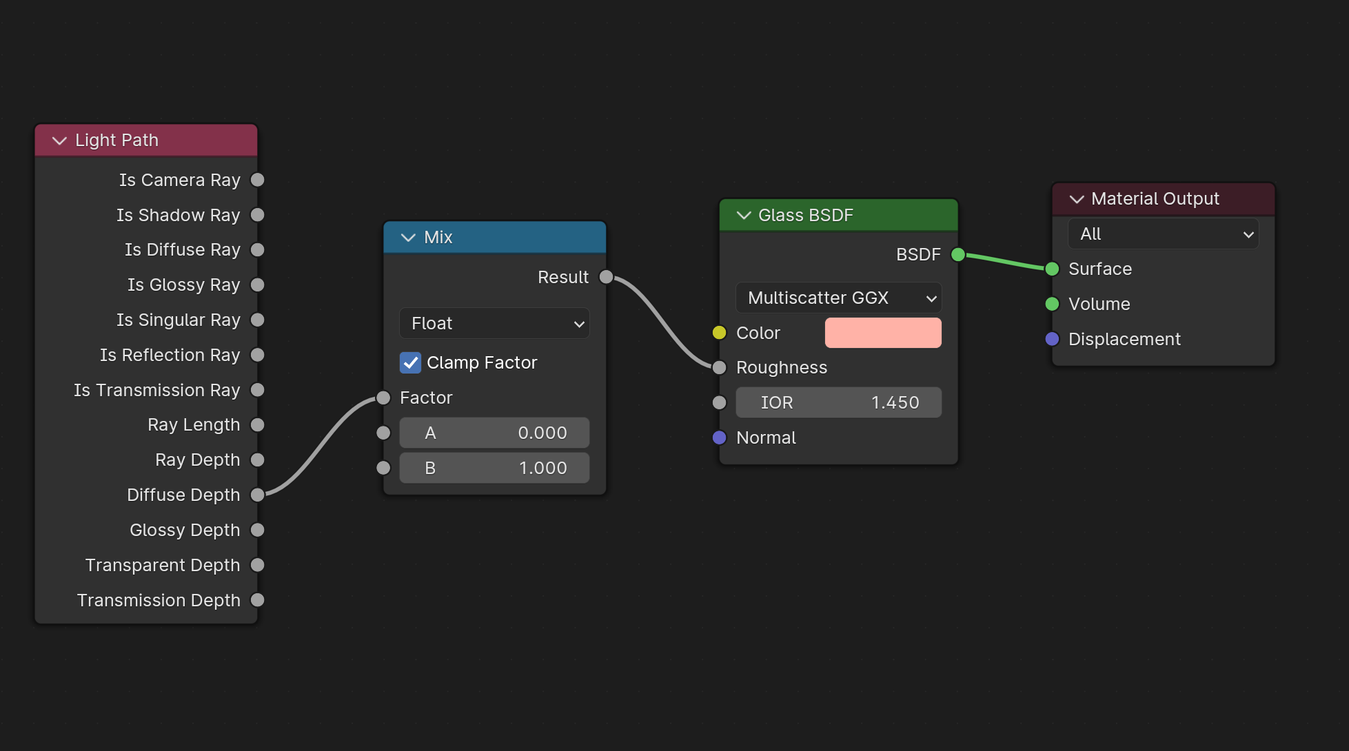
This setting can be found in the Render Settings - > Light Paths -> Caustics -> Filter Glossy section.
Note: Increasing the Filter Glossy setting will decrease the accuracy of caustics through the glass. Because the caustics are being rendered as if the glass is rough.
Make it so NEE works with glass:
There is a technique to try and make NEE work with transmissive materials like glass. It’s called “Manifold Next Event Estimation”. The idea is simple. Do NEE, but take into consideration the distortion of the ray as it passes through the glass material.
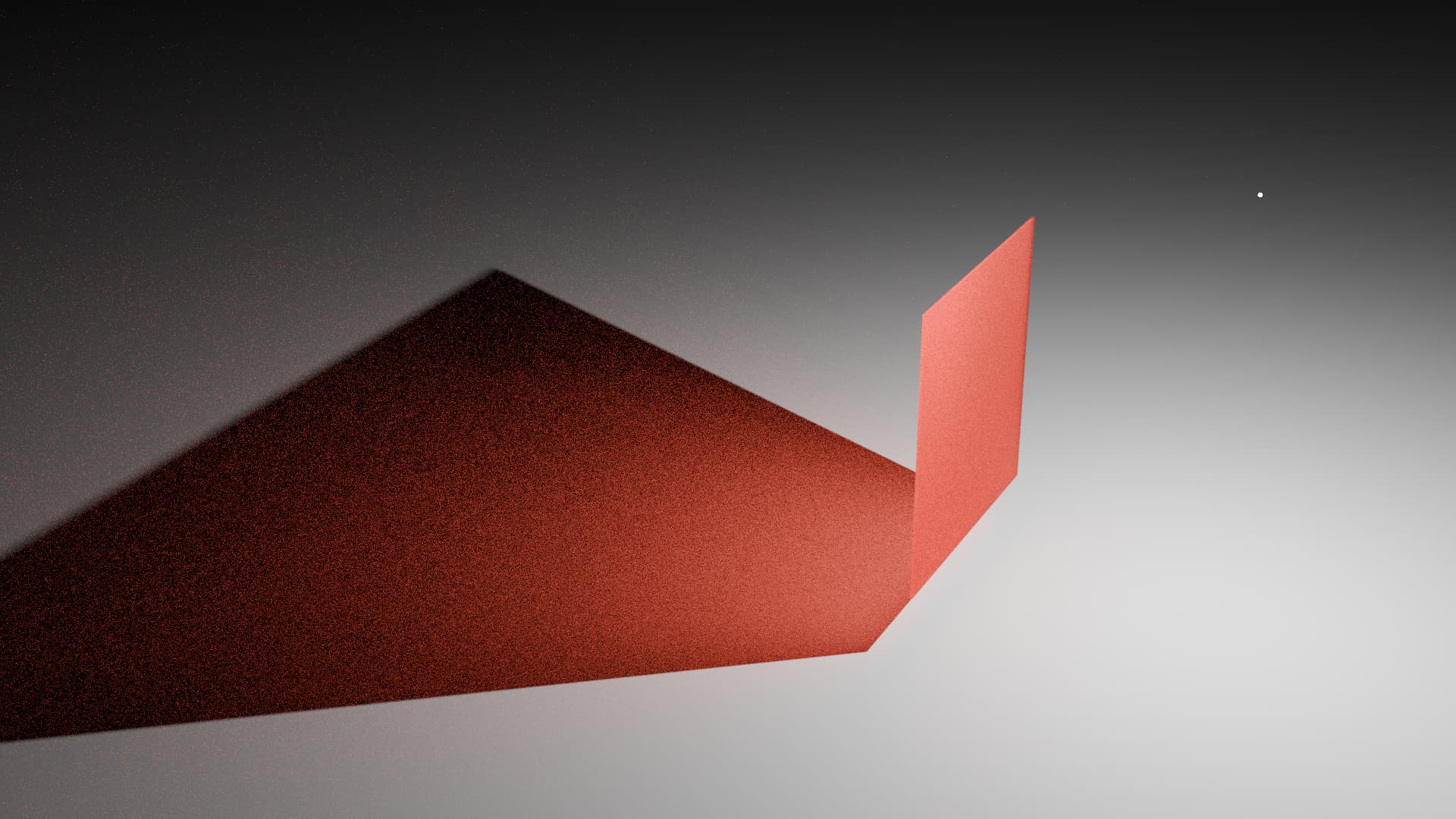
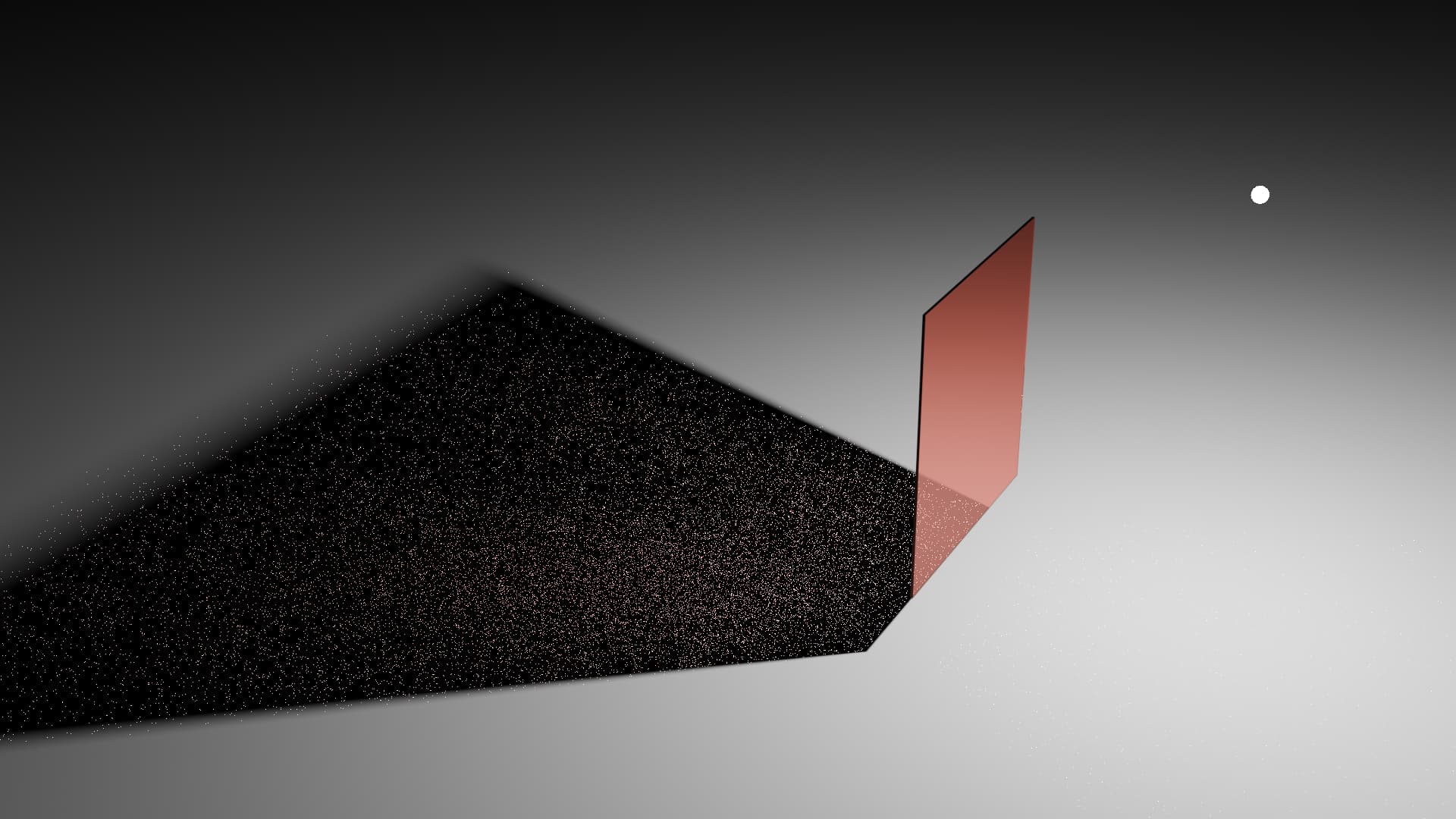
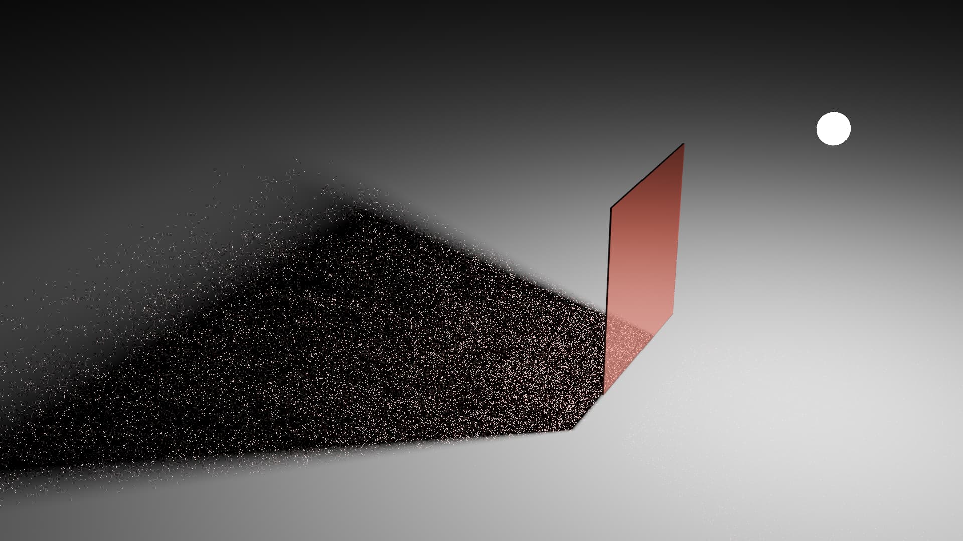
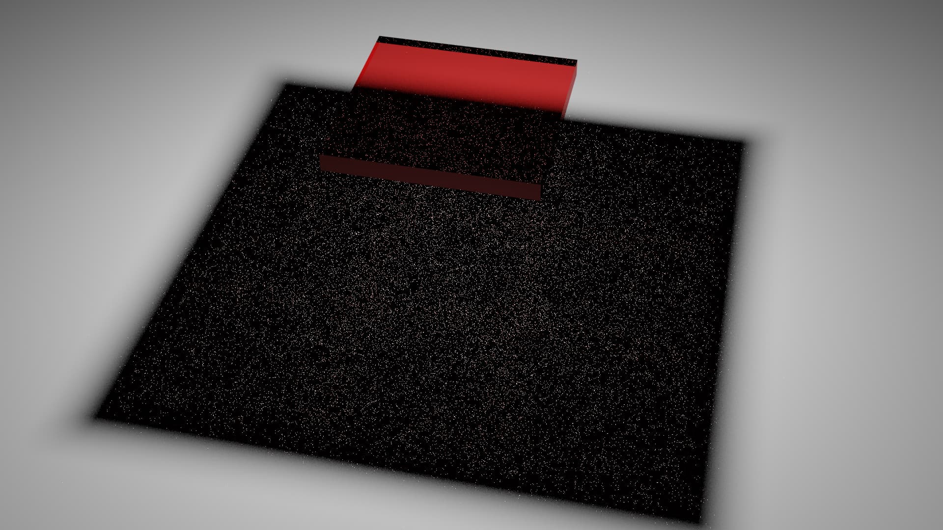
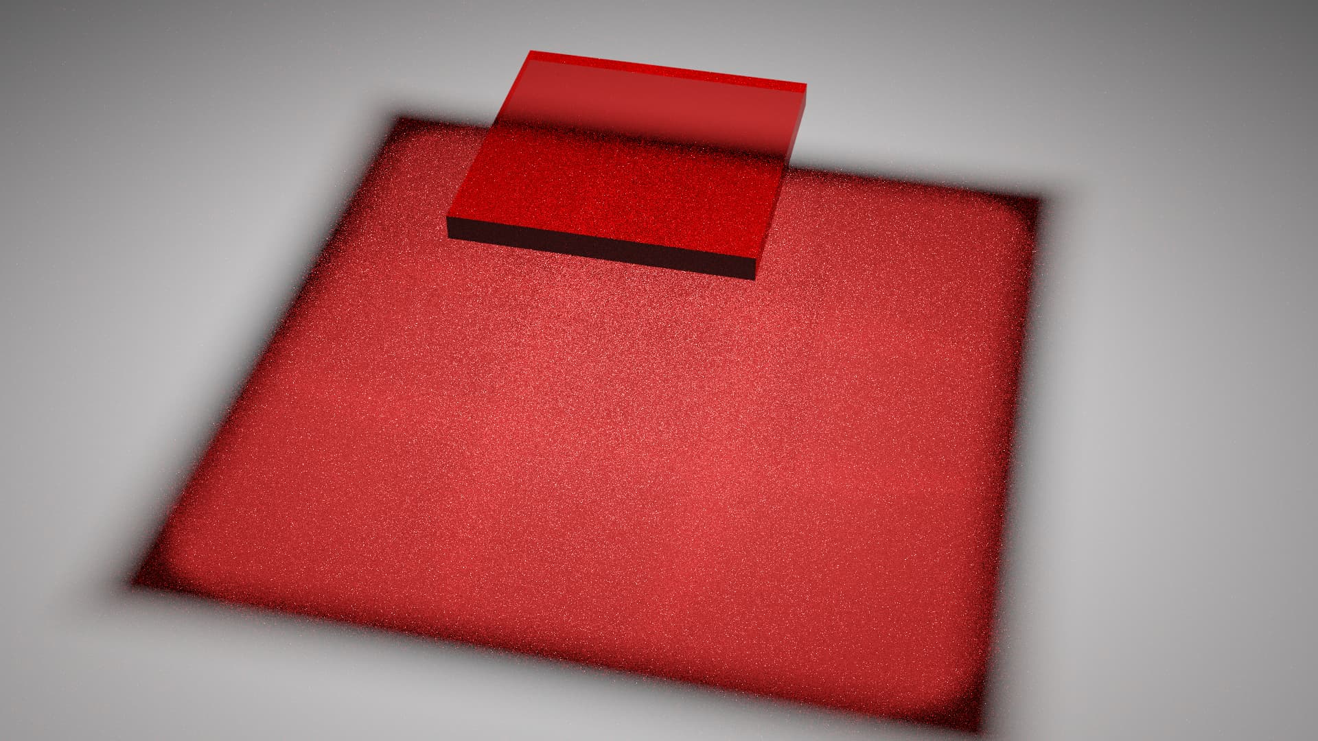
Cycles has this feature. It’s known as “Shadow Caustics”.
You will of noticed something. There’s a section of the “shadow” that is just black, when it would be expected to be red. There’s quite a few limitations with the Shadow Caustics feature, and one of them is causing that issue. I can’t remember the technical details on why this happens, but it’s a known issue and so Manifold Next Event Estimation is usually only used for specific setups (E.G. Rendering light passing through the cornea and onto the iris in an eyeball). Maybe it can be improved in the future?
Make it so the random rays are more likely to hit the light:
I mentioned earlier that when a ray hits a diffuse surface, it can decide to do NEE or continue tracing rays randomly. Well the “continue randomly” method is how a lot of the light passing through the glass is actually sampled. So what if we improve this?
There are many ways of doing it, but I’ll only mention a few.
Learn which way the light is coming from:
If the ray tracer had some way to learn which directions the light was coming from, even when bouncing off and passing through other objects, then that learned data can be used to help guide rays to focus on those important regions.
Cycles has feature for this, it’s called Path Guiding. Currently it can only be used on the CPU, but Intel is working on GPU support.
Disclaimer: Path Guiding is not designed to solve caustics. It’s just that as a side effect of how it works, it can help with caustics solving.
Make the light easier to hit:
The main issue with randomly hitting a light through a piece of glass is that the light is so small from the perspective of the ground in the shadow of the glass, that picking random directions that actually hit the light is unlikely. So if we could make the light appear bigger to the ground, then that will increase the chance it get’s sampled. The main ways of doing this are increasing the size of the light, and moving it close to the ground object. Obviously this technique can only be applied in select situations.
And then we can combine some of these technique together.
So here’s an example showing what a small increase in light size, path guiding, and a bit of filter glossy can do.
Normal rendering vs Adjusted rendering
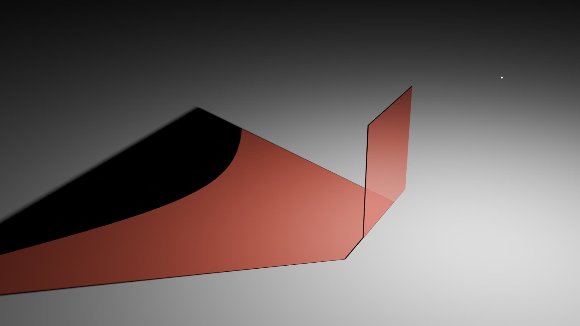
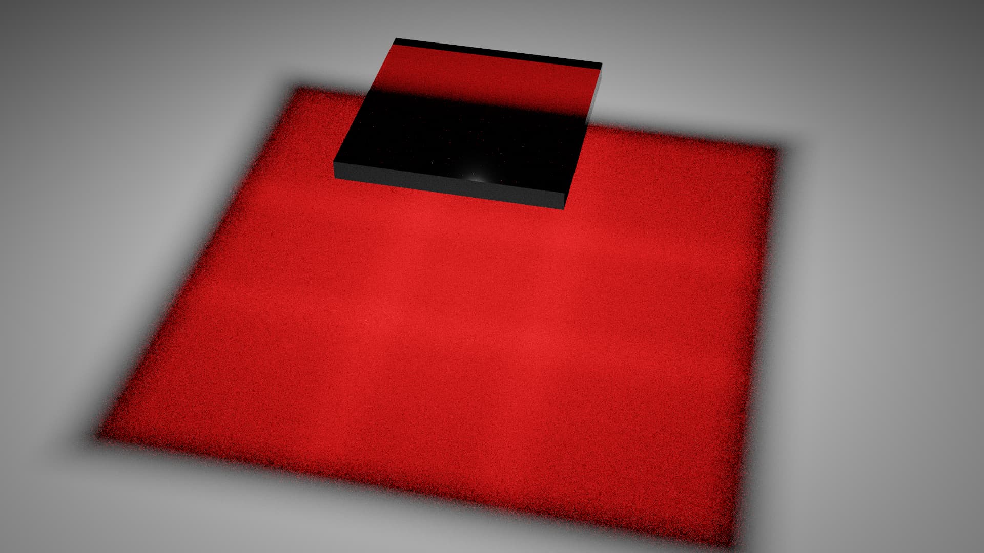
Original:
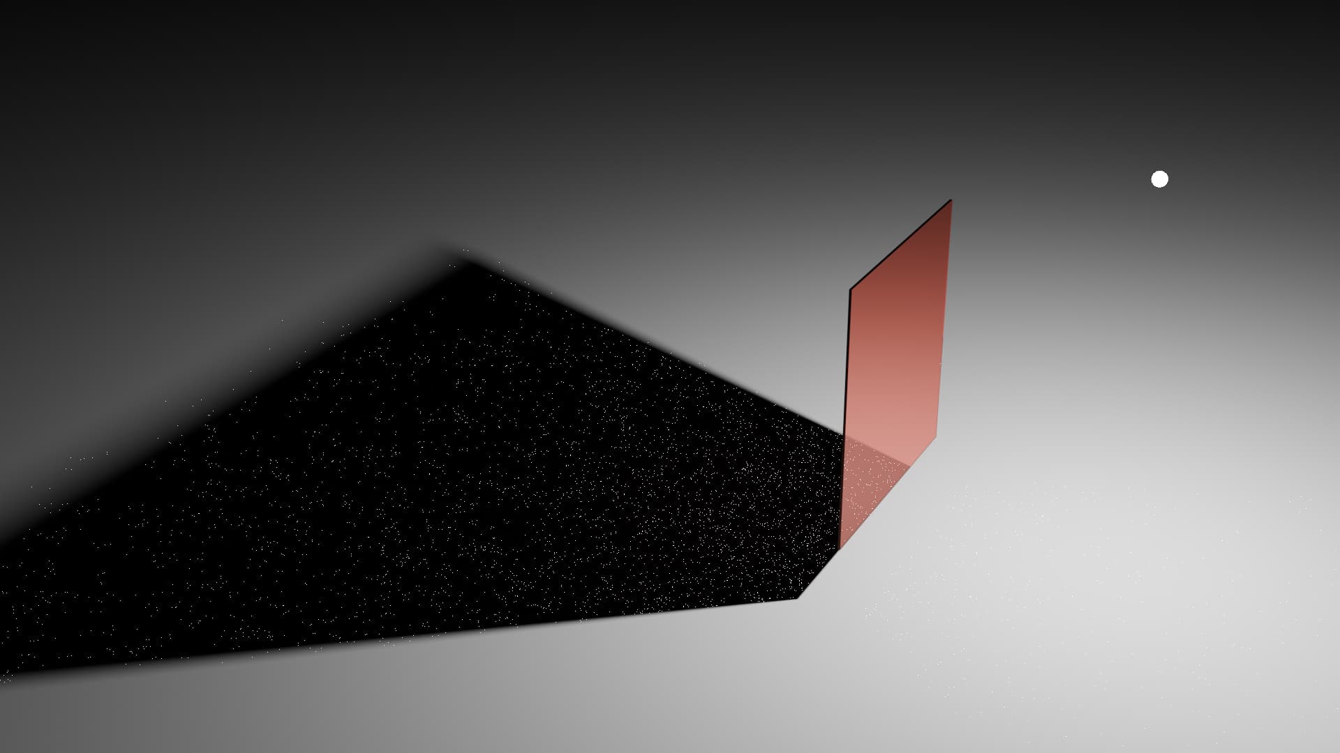
Slightly bigger light, path guiding, and a little bit of filter glossy:
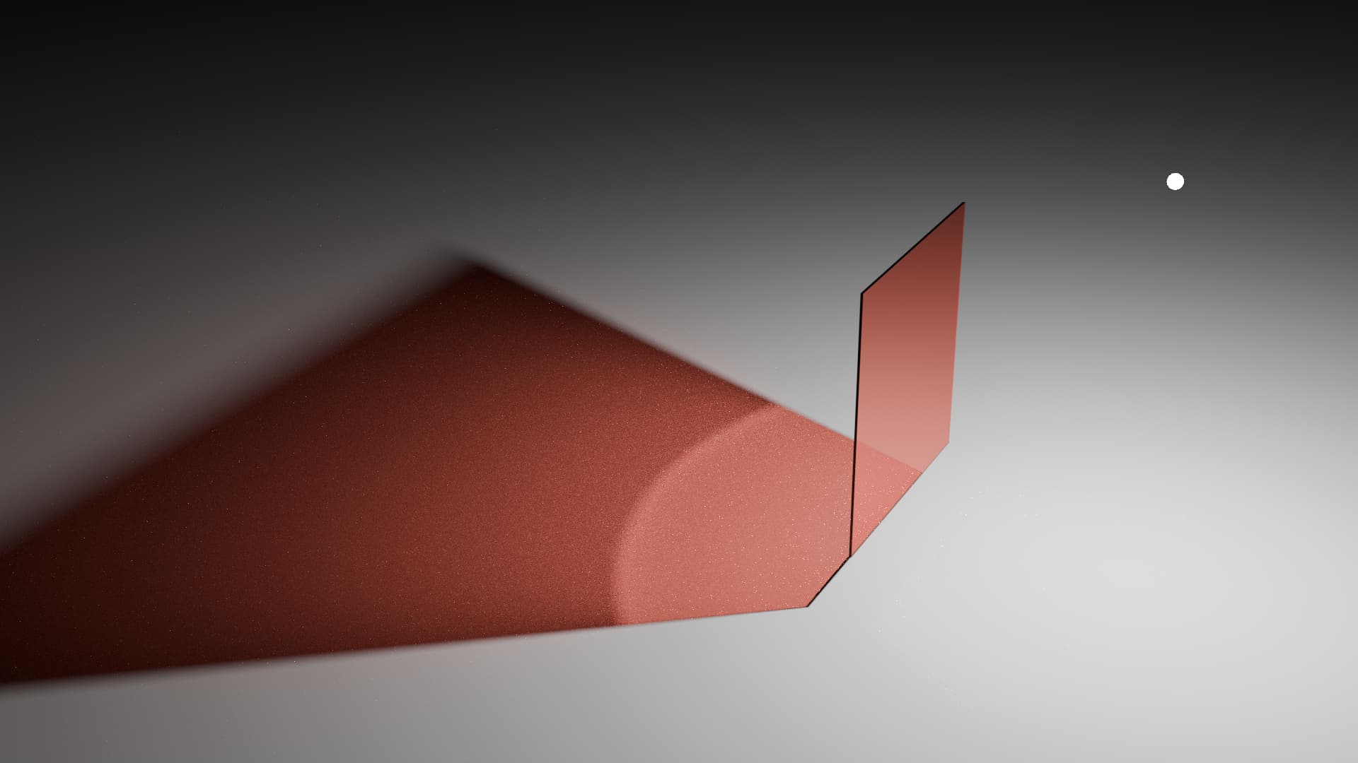
Note: This is what changed between the original scene and the modified scene:
- Light radius was increased from 0.01m to 0.05m.
- Filter glossy was increased from 0.0 to 0.2.
- Path Guiding was enabled.
Other techniques:
There are obviously other techniques that can be applied to help out with this situation. Or modifications can be made to existing techniques to make them better.
Reverse the ray tracing direction:
The main issue we have with sampling light through a piece of glass is that it’s unlikely that a ray will hit the ground, then randomly pick a direction that actually hits the light. But what if we did it the other way? We trace rays from the light to the ground?
Well, you get a similar issue. It’s unlikely that the ray will hit the ground and pick a random direction that hits the camera.
But if you combined “light to ground” with “camera to ground” ray tracing, you can get the benefits of both approaches.
This technique is known as “bi-directional path tracing”, or a modified form of it can be used called “photon mapping”. Cycles doesn’t support these techniques. I can’t remember if there was a specific reason it isn’t supported, or if it’s just a “we haven’t gotten around to it” thing. So you’ll need to wait for a comment from a Cycles developer about that.
And just a quick recapper thing.
The glass is not broken. It does allow light through it. It’s just that depending on the scene setup and render settings, it can be hard for Cycles to sample light through the glass.
If your only desire was to sample the light more often, without using any tricks, then Path Guiding and bi-directional path tracing are the kinds of options you want to pick. Maybe increase the light size if you can.
But if you’re willing to loose some accuracy, you can adjust the filter glossy settings and use the architectural glass trick.
24 Likes
I just wanted to add notes about this specific video.
In the beginning the user talks about how no light passes through the glass when refractive caustics is turned off. This is expected. By turning off refractive caustics, the user is turning off the ability for the light to pass through the glass.
The user then shows that Luxcore doesn’t have this issue (comparing Cycles with Refractive Caustics off to Luxcore with Refractive Caustics on). This was an unfair comparison.
During part of this demonstration, they mention that the sun doesn’t pass through the glass in Cycles, even when using Refractive Caustics. It looks like the sun is extremely small, making it hard to impossible for rays to go through the glass and hit the sun. When they switched to Luxcore, it had the same issue, the sun wasn’t shining through the glass. So them mentioning that Cycles had this issue, while luxcore didn’t, was based on the fact they didn’t notice this issue in luxcore in their testing.
After that they switched to using the Luxcore glass material for their demonstration. The Luxcore glass material had the “architectural glass” trick enabled. Meaning they are comparing architectural glass in Luxcore to normal glass in Cycles. Another unfair comparison.
So some of their judgements about the down falls of Cycles glass is based on the fact they are comparing different render settings and material setups between Cycles and Luxcore.
If the user had used the comparable render settings between both Cycles and Luxcore then their experience with whether or not light passes through glass would be very similar in the two render engines.
I should also mention that the default render settings for Cycles would make Cycles comparable to Luxcore in their scene. But the user wasn’t using Cycles default settings.
Obviously, luxcore still has some advantages over Cycles in this area. Photon mapping, Bidirectional Path Tracing, Light Tracing, etc. But this didn’t seem to be what the user was concerned about.
5 Likes
Thanks, Alaska, for the thorough breakdown.
Considering the various adjustments and workarounds needed to address these obvious concerns in the Cycles glass node, it appears that there are challenges with its default behavior.
The reliance on tweaks like lowering light objects, adjusting sun size, and implementing lightpath tricks suggests potential shortcomings in achieving desired results without additional adjustments.
The fact that many users resort to these hacks rather than relying on the default settings raises questions about the effectiveness of the glass shader for rendering glass objects. If these workarounds are commonplace, it may be worth exploring improvements or refinements in the default properties of these glass objects.
Many of the default render settings in Cycles are alright for rendering glass. For example:
- Filter glossy is set to 1.0 by default to allow light to transmit through glass easier.
- Refractive Caustics is enabled by default to allow light to pass through glass.
- The default sizes for lights are not 0 so they can render through glass even when filter glossy is set to 0.
The main “hacks” that people seem to use are:
- Architectural Glass (which people use in both Cycles and Luxcore due to it being a huge benefit for interior scenes in both render engines)
- Increasing light sizes (which people will do in both Cycles and Luxcore)
- And using techniques to help light get through the glass (Light tracing, path guiding, Manifold Next Event estimation, etc, which people use in Cycles and Luxcore)
These “hacks” aren’t exclusive to Cycles. They exist in most ray tracing render engines.
The difference is that Luxcore (and some other render engines) offer some extra tools that you can turn on that help with rendering glass.
Here are some example images:
Note: All renders were done at 64 samples per pixel
Note 2: The renders aren’t an exact match. This was a quick test.
Renders
Luxcore Default Settings:
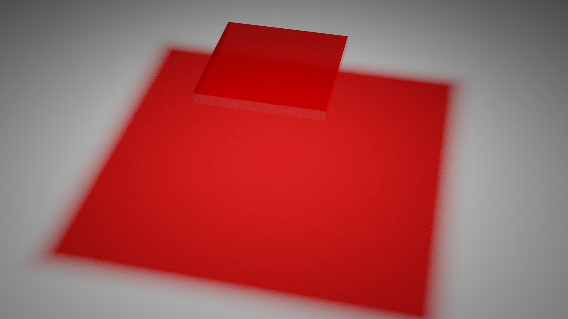
Cycles default settings:
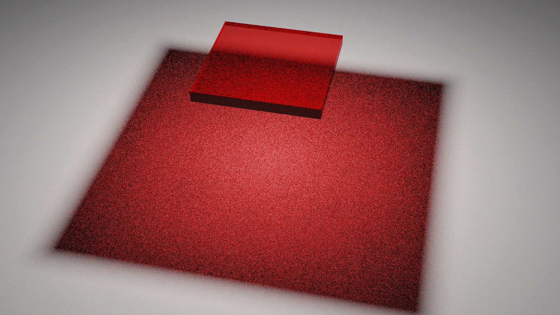
Adjust Cycles settings to try and match Luxcore Default (set Filter Glossy to 0):
Luxcore Architectural Glass:
Cycles Architectural Glass:

Luxcore with light tracing:
Cycles with Filter Glossy 0.2 and Path Guiding:
Based on the renders above, Cycles seems to do better than Luxcore when rendering glass by default.
When using Architectural Glass, they’re basically the same. However, in luxcore it’s a simple tick box. In Cycles you need to create a specific node tree. Cycles will likely receive a tick box for this option at some point in the future.
When using features offered by the render engine to improve glass rendering (light tracing, path guiding, filter glossy), they seem kind of similar in this scene, with the exception being that Cycles can see the caustics cast by the glass through the glass. And the light tracing option is better than Path Guiding as a general caustics solver. Along with that, light tracing is more accurate than using filter glossy.
19 Likes
I was wrong about this one. Point and spot lights have a default size of zero. All other light types have a size other than 0.
2 Likes
This is a minor issue but a usability problem. Normally using the backspace key on an input value in Blender resets to the default value (acceptable starter values), however using the backspace key on the principled BSDF shader numeric value inputs just resets them to zero instead of resetting them to their good defaults. For instance the default IOR is 1.5, pressing the backspace on IOR resets it to zero now instead of resetting to 1.5 as the generally expected behavior. To be honest being able to reset to their proper defaults is a good user facing feature.
We actually have this issue with some of the nodes in the compositor and the shader graph like the hue/saturation node.
7 Likes
Apparently this is a general issue with nodes in Blender. They just don’t support default values. It’s good to have more people reporting this, hopefully it’ll get fixed. With how prominent nodes are becoming surely this will become a priority
7 Likes
I mentioned the issue several times before and the last time when the main parts of “Principled V2” started to land in main.
Being able to reset options to a sensible value is so important and compared to other parts of the ongoing development of Blender it should be easy to get it right.
6 Likes
Yeah and it’s not only related to nodes, many areas in Blender lack default values when resetting: #92533 - Resetting singular values in the Themes disables them - blender - Blender Projects
4 Likes
Yes, it’s all over the place. And I still am willing to volunteer filling in the missing values.
As far as I know these are set in the Python code. It would be nice if this is fully disabled or fully enabled all over the UI, because as of now it feels confusing given it is hard to know which ones behave properly which ones do not. I am used to dealing with some of the nodes already by making a duplicate of the initial nodes before working with them, but this is a rather cumbersome approach.
For calculating Fresnel there are typical two equations used.The dielectric equation and the conductor equation.
But for some dielectrics that have absorption they have nk values too,but the equation here is a bit different vs the conductor.For these lossy materials,that have absorption k values that gives the attenuation in the medium.The equation is basicly a Beer-Lambert attenuation
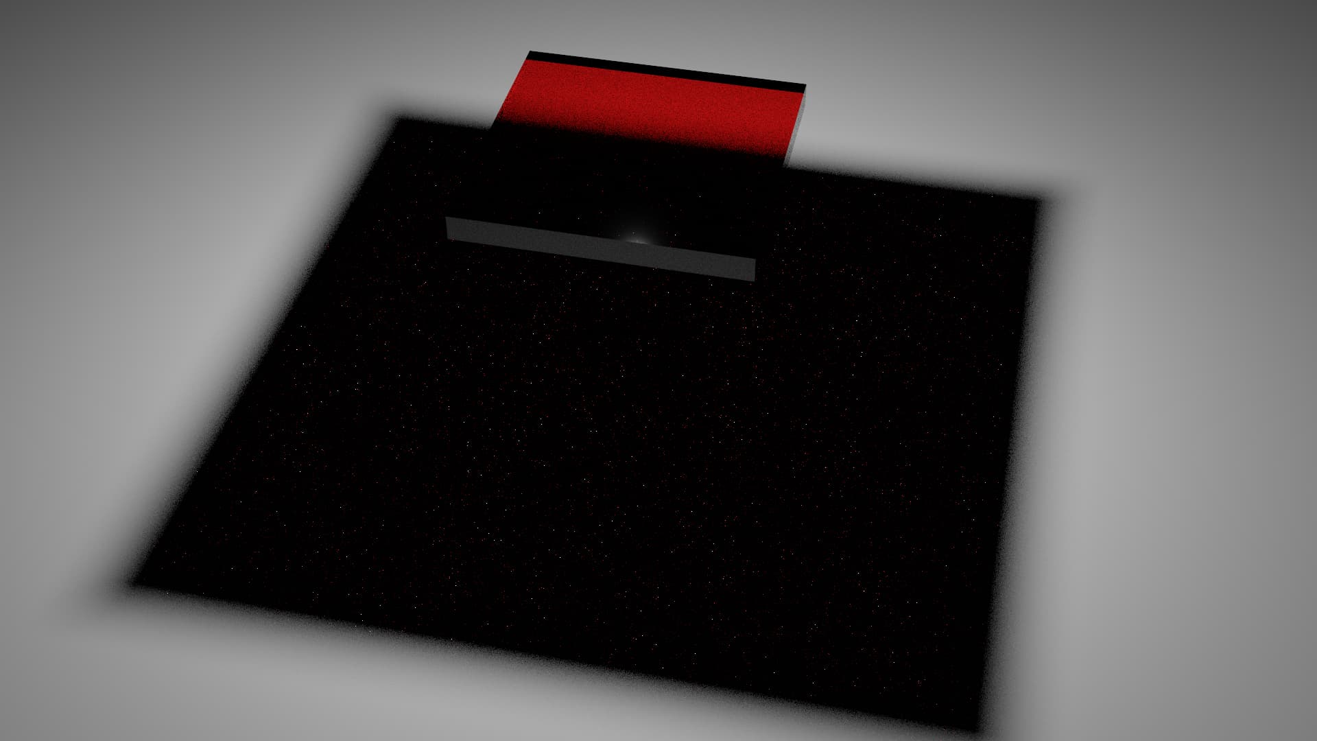
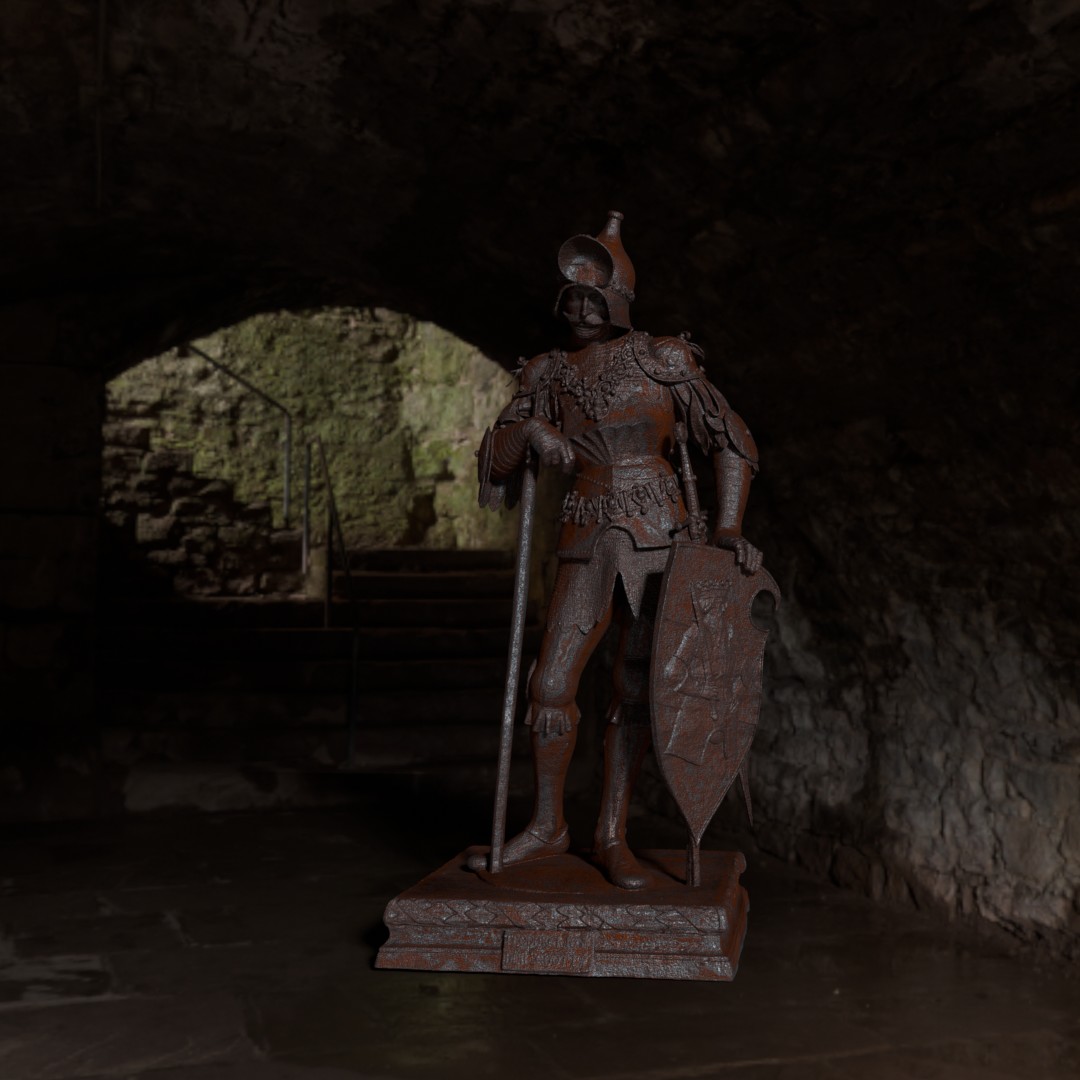
Here a example of Iron conductor with wolf and gulbrandsen equation into the principled shader,
and the added Beer-Lambert equation for a dielectric nk behavior.
Notice,that without the Beer-Lambert equation,the color would be almost the same greyish as the iron layer.
For this example i added a (Fe3o2) Rustlayer based on the refractive nk values from the refractive index site.
1 Like
I’ve been using Blender 4.0 with a new principled shader and I would appreciate if someone can explain the implementation of the roughness.
For example, I have a map for the roughness that goes from 0 - 1. If map is 0 it will produce almost a mirror type of specular, if it is at 1 it should be a completely rough material where specular doesn’t exist, we should see only diffuse reflection at 1. However, for some reason Principled V2 material still produces specular reflection even at roughness value of 1 which makes material look white under certain lighting conditions although diffuse is colored. If the roughness is at 1 shouldn’t we be seeing only a diffuse component of the material? I tried this in other render engines and I see the same behavior in Redshift and also Iray in Substance Designer. However I don’t see this in OpenGL rendered in Substance Designer.
You mean roughness of the metallic material ? Afaik these roughness reflections are based on microfacets.Like tiny mirrors which gets more and more steeper angled with increased roughness value.
If you have no metallic and only diffuse material and dont want a Fresnel like reflection,then you have to set the specular to 0.And make sure you dont have any clearcoat added.
Roughness of the basic non metal material. If the roughness is set to 1 should material switch to full diffuse at that point and not use any microfacets reflections from GGX?
So for example I have a ground with some rocks scattered around it. Rocks have a bit of specularity because they tend to have lower roughness. However, ground is just a pure dirt that should be 100% diffuse without any specular. But even if I set roughness to 1 I still see reflections of the light. I am wondering is this physically correct or?