I tend to agree with this. I don’t see a downside to labeling things clearly. For the longest time (years ago) I didn’t realize that’s what these 3 channels did.
5 Likes
I agree with this too, even if internally the input is still a vector, the labels should be Red, Green and Blue.
It is not enough. If any particular parameter in the application by default accepts a negative value, the slider needs to be able to be dragged to a negative value.
But with the Subsurface Anisotropy setting, although you can type in a negative number, it does nothing because Subsurface Anisotropy is clamped to [0…0.9]. So although the UI supports negative values, it’s a waste of space and will cause confusion to expose negative values to users by default because it does nothing.
A lot of other sliders on the Principled BSDF can also support values below their minimum and above their maximum, and it actually has an impact on the material (at least until a few weeks ago). But the Blender foundation does not expose the ability to drag values into these ranges by default because they are uncommon, unsupported, and/or physically incorrect. Exposing the full range of supported values by default for many of the Principled BSDF inputs will cause confusion, frustration, bug reports, and slow down peoples work flow that want to just experiment with material properties without having to worry about making sure everything they slider they drag is still a physically correct value.
1 Like
Not every artist’s goal is a physically correct result.
1 Like
Then those artists can type in physically incorrect values.
Note: I know I made a change recently which clamped a lot of values, reducing the ability to create many physically incorrect materials. I’m working on reverting some of this and only clamping what’s necessary.
2 Likes
I don’t want to derail the thread, but I’d like to give feedback about the Principled node UI. And in case also for other nodes UI enhancements, like nodegroups.
Is there any open thread about it?
little teaser:
for the sake of cleaner and less crowded nodetrees, Principled node can be cut to the PBR essentials, hiding the more advanced stuff. A click on the expander icon will show the full potential. In case something is connected to the advanced sockets, the collapse button should be grayed out
Soft limits are there to inform the user about realistic/sensible ranges. Hard limits on the other hand can be much wider or non-existent
@lsscpp there are already two coexisting ways of compacting nodes, now we’ve got panels too, and you’re suggesting a fourth layer on top of all that. I see the reasoning, but shouldn’t this be handled by a more generalized socket-hiding/compacting method ?
4 Likes
May be one year later this variant for principled node UI become actual? ![]()
1 Like
I think what you’re suggesting here could be a solution to the ‘Hide Unconnected Sockets’ state not indicating to users that there are hidden parameters, which is currently a problem when people open someone elses file. Personally I’d go for a solution that indicates this without making the panel longer, though, such as a symbol in the header that has a more verbose tooltip that clarifies what it means.
Actually, we already have the rollup arrow in the header, a second one that only displays when there are hidden nodes makes sense to me. Like the conditional button that appears above the viewport when you’re in Local View.
But yes, this is an unrelated discussion, so I’d also welcome another thread.
2 Likes
Not only that, but the way it’s set up I think it’s sensible in the way that it sets the soft limit in a stepped way once you go past it. (if you type in 3, your new soft limit will be 5, so you still have room to drag the slider up, but if you put in 12 you can drag it as up as 20 before having to input another one manually…and you can always drag down to 0 again directly). To me, that’s a balanced compromise. Maybe you could set up a preference for “always be able to drag indefinitely” or a modifier key to overcome the soft limit when dragging…I personally don’t think it’s that sorely needed, but maybe I’m wrong.
Why is that clamped?
This means it is clamped in the shader itself.Makes not much sence to me,since you could choose what type of phase function you need.
I guess most artists useing 0 as default,I mean why restricting a function its allready there?
1 Like
The manual has been updated now with the new parameters.
https://docs.blender.org/manual/en/4.0/render/shader_nodes/shader/principled.html
It also includes this explanation for Random Walk (Skin):
Random walk method optimized for skin rendering. The radius is automatically adjusted based on the color texture, and the subsurface entry direction uses a mix of diffuse and specular transmission with custom IOR. This tends to retain greater surface detail and color and matches measured skin more closely.
Node sockets don’t support hard limits currently, unlike other types of properties. This should get implemented at some point.
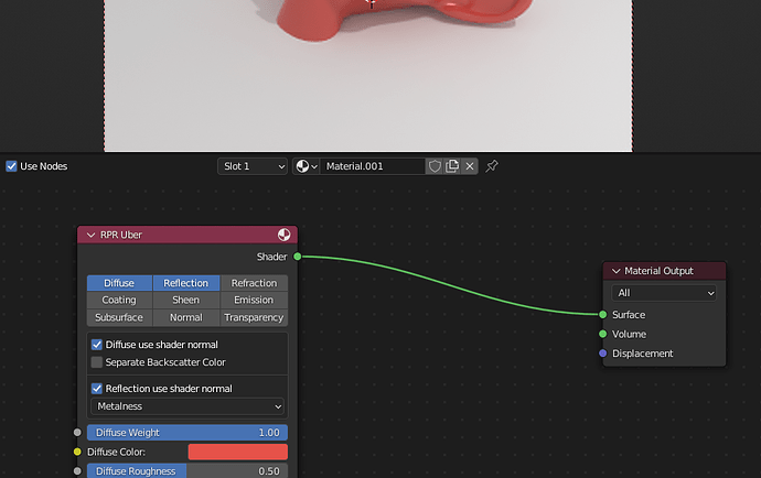
Because I don’t think the color is representative of what it’s doing. High values will show white, low values black, regardless of the color tint.
But, we should really add Red/Green/Blue labels to those buttons. We just haven’t gotten to it yet.
There is a lot of discussion about this earlier in this topic. For me the main reason to stick with panels is to have a single consistent mechanism for organizing properties throughout the user interface.
I’ve added it as a to do item in the Principled v2 issue to look at this again.
For the reason explained here:
16 Likes
Yes! This is exactly what I’m asking for, not a color picker field, so all good then ![]() The input should also by a color input and not a vector input, but this is not that important IMO and more like nitpicking.
The input should also by a color input and not a vector input, but this is not that important IMO and more like nitpicking.
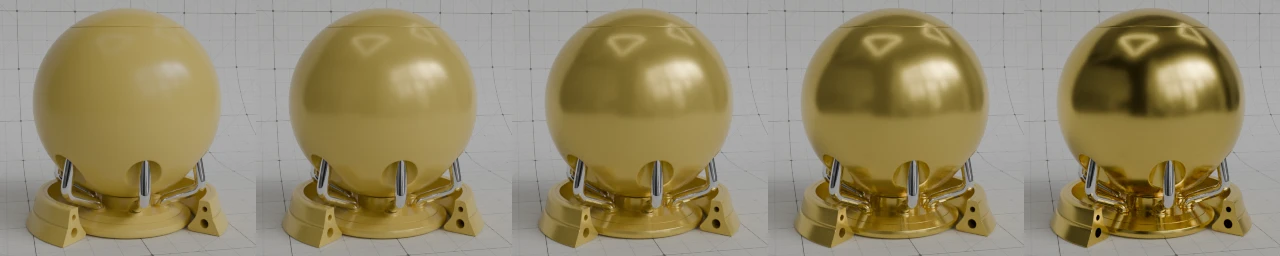
Just as an fyi personally I really don’t use radius values higher than 1 here anyways, because if I want larger radius I just up the scale instead ![]()
Looks good. This is probably nit-picky of me, but I can’t help but notice the subsurface example images don’t apply the material to the base of the model the way it is in the other examples. I mostly mention it because I think the base might actually be the best part of the mesh to really demonstrate the subsurface scattering effect.
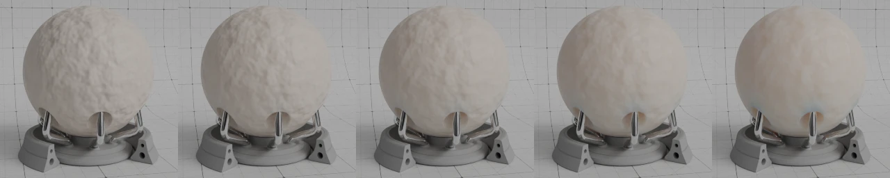
7 Likes
There needs to be some kind of connection indicator there. Otherwise - exactly, yes - it looks like you have a wire connected to perhaps another node that is inadvertently hidden under the BSDF. More than once I’ve started dragging the BSDF node around trying to rearrange things, looking for what the heck … oh, right… it’s actually that one.
3 Likes
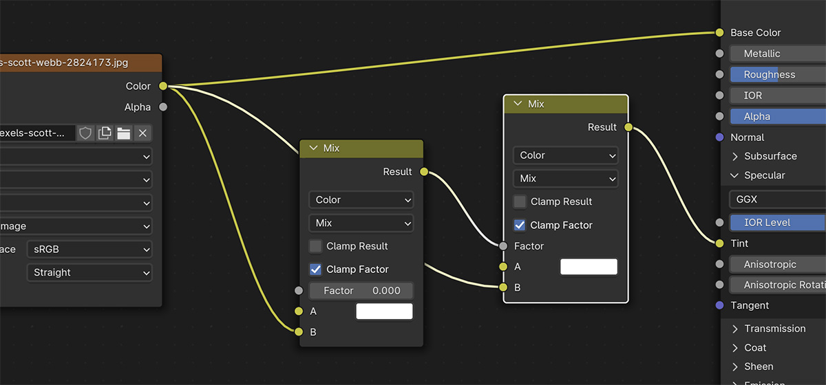
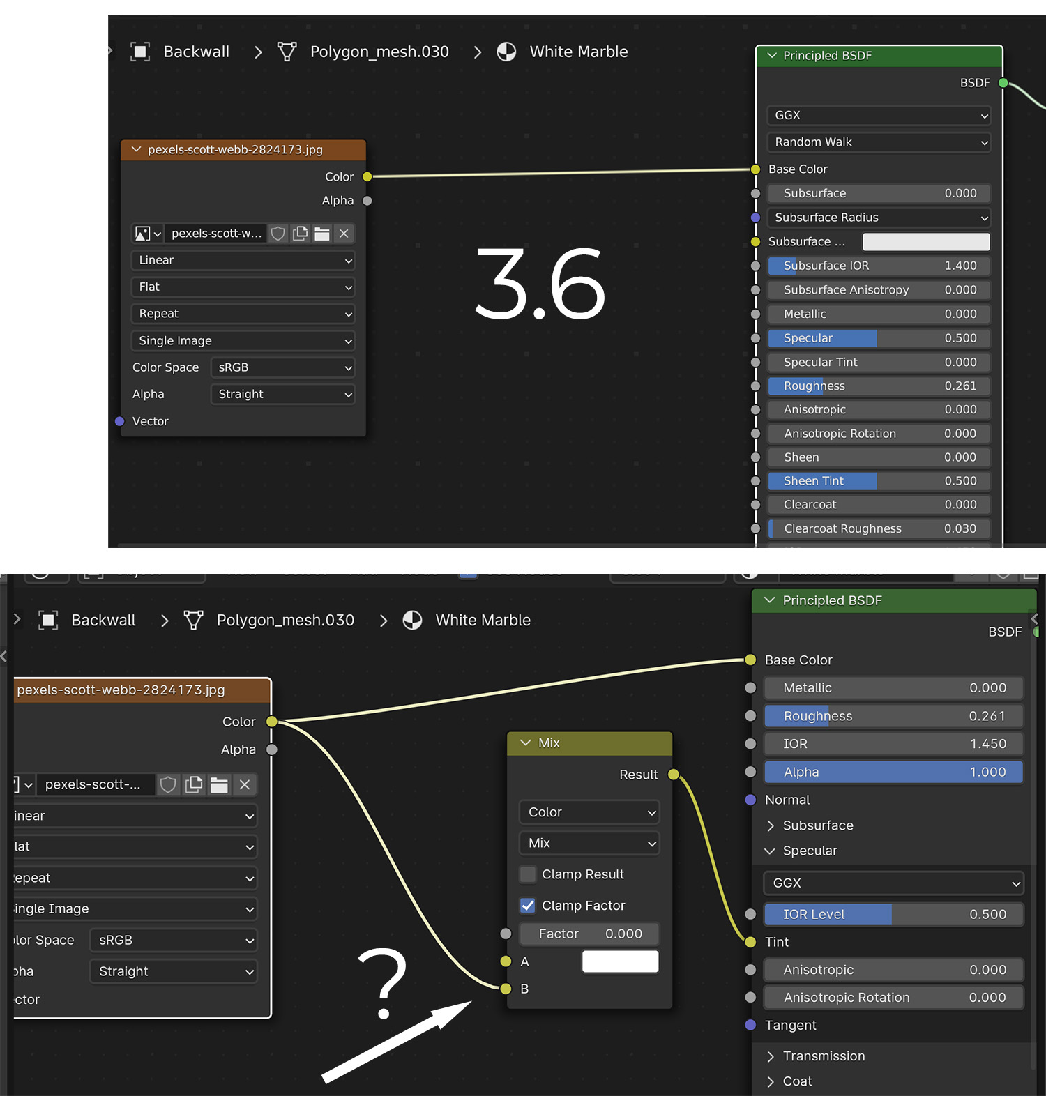
Something is going on with conversion of 3.6 principled bsdf’s into the 4.0 version. If a 3.6 principled BSDF has an image texture going into Base Color, when you open into 4.0, a new Mix Color node is there with this same bitmap that then goes into Specular Tint. I can’t figure out why it would do that, but it’s necessary to delete these for the material to match 3.6.
If you save this file in 4.0, then open in 3,6, save again in 3.6, and reopen in 4.0, it begins adding a chain of these mix nodes, one going into Fac of the next.
3 Likes
Specular tint is an input to adjust the tint of the specular component of the “base” material.
Back in 3.6 and many older versions, it was a simple slider from [0…1]. 0 means leave the Specular Tint white. 1 means make the Specular Tint the same colour as the Base Color input. And inbetween values were mixes between the two.
In 4.0 with the new Principled BSDF, the Specular Tint input is a color input, meaning that you specify the tint color directly rather than mixing between white and the base color. This allows for more artistic control. However, to convert 3.6 files to 4.0 and have them look roughly the same, extra nodes need to be added to simulate that “mix between white and base colour” behaviour of previous versions of Blender. So a mix node is added that mixes between white and the base colour based on the Specular Tint value in the old file.
Based on my testing, everything is working as expected. But you have an issue when you open a 3.6 file in 4.0, save it, open it in 3.6 again, save it, then open it in 4.0 again.
Here’s what’s happening:
- You open your 3.6 file in 4.0. The mix node will be added, and results will look similar to 3.6. Versioning is working correctly.
- You then open your 4.0 file in 3.6. There’s no versioning to convert the material back to what it was before hand. Either because it was missed during development, not included in 3.6 yet, or it’s too difficult to handle (E.G. How does Blender know that the mix node was added there by the 4.0 versioning and knows that it, or it’s inputs, hasn’t been modified in some way since the file was last opened in 3.6?). Due to the lack of versioning, 3.6 will just use the node setup created in 4.0, and the material will now render differently in 3.6 compared to what you started off with.
- You then open that file again in 4.0. Versioning will be applied. And all the versioning being applied is correct. So now the 4.0 file will look similar to the “different” 3.6 file that you produced in step 2.
2 Likes
Agree with this, in all my tests I’ve had to delete that extra Mix node too because it changes how the original shader looks.
Maybe it should be fixed so this Mix node is only added if the specular tint was originally set to a value other than 0. Otherwise is messing up the original material
2 Likes
I think this mix node going into Spec Tint should only show up with the spec tint value of the incoming file is above 0. It’s just going to add confusion. Right now the Mix node Factor just sets itself to zero, which is the functional equivalent of not having a node there.
Additionally, all incoming materials aren’t treated the same, only materials with a node going into Base Color do this. As long as Spec Tint is zero, setting the Spec Tint to white seems sufficient. If it’s above zero, then yes the mix node is needed.